Advertisement
Quick Links
DS-KD8023-E6
D Series Door Station
UD19916B
E N G L I S H
Diagram References
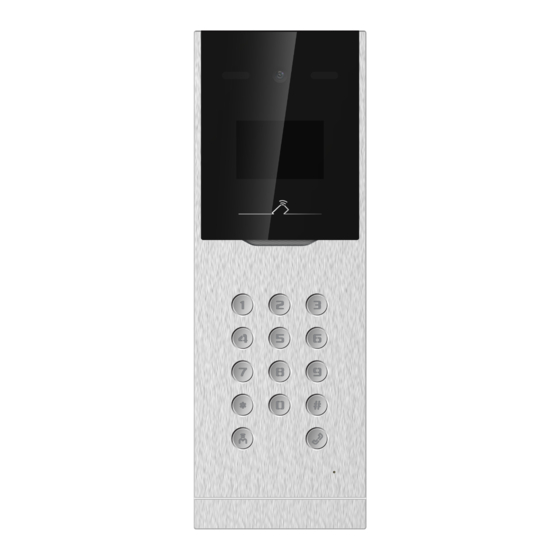
Appearance
1
1
2
3
4
IR Supplement Light
Camera
LCD Display Screen
Card Reading Area
6
7
8
9
10
Keypad
Call Button
Call Center Button
Microphone
TAMPER
Note: The appearance of the device vary according to different model. Refers to the actual device.
Terminal
2
485A-: RS-485 Communication Terminal
DC 12 V: Power Supply Input
AO1+/AO1- : Alarm Relay Output 1
485A+: RS-485 Communication Terminal
AO2+/AO2- : Alarm Relay Output 2
TAMP: Wiegand Card Reader TAMPER
OK: Card Reader Indicator Output (Valid)
NC1/NC2: Door Lock Relay Output (NC)
NO1/NO2: Door Lock Relay Output (NO)
ERR: Card Reader Indicator Output (Invaild)
BZ: Card Reader Buzzer Output
COM1/COM2: Common Interface
AIN1/AIN2/AIN3/AIN4: Alarm Input
W0: Data Input Interface Wiegand Card Reader
BTN1/BTN2: Door Contact Detection Input/Exit Button
W1: Data Input Interface Wiegand Card Reader
SEN1/SEN2: Door Contact Detection Input/Door Contact
RES: Reserved
GND: Grounding
Note: Wiring description refers to the User Manual.
3
Installation
Before you begin:
1. Accessories that you need to prepare for installation: gang box and mounting template.
2. Make sure the power supply meet the power requirements of the door station (12 VDC, 1 A).
3. Make sure all the related equipment is power-off during the installation.
4. Wire the cables before installation.
Accessory
The dimension of the gang box is: 407.5 mm(W) × 135 mm(H) × 55 mm(D).
The installation hole should be larger than gang box. The suggested dimension of the installation hole
is 408 mm(W) × 135.5 mm(H) × 55.5 mm(D).
Flush Mounting
1. Drill an installation hole on the wall.
Note: The size of the hole should be larger than that of the gang box. The suggested size of hole is 408
mm(W) × 135.5 mm(H) × 55.5 mm(D).
2. Insert the gang box into the hole and fix it with 4 PA4 screws. Make sure the edges of the gang box
align to the wall and the hook A and hook B of the gang box hook onto the wall.Route the cables of the
door station through the cable hole.
3. Insert the door station into the gang box and then move the door station downward to hook the lock
catches on the rear panel onto the hook C of the gang box. Fix the door station with 2 PM3 screws.
4.After fixing the door station onto the gang box, secure it by inserting the plate and insert 2 POM2
screws.
Configuration
4
Activate Device
1
You are required to activate the device first by setting a strong password for it before you can use the device.
1. Power on the device to enter the activation page automatically.
2. Create a password and confirm it.
3. Press # to activate the door station.
Note:
Enter an 8 to 16 characters admin password.
When entering the password, taking the numeric key 2 as example, press the numeric key 2 once, the text
field shows "2", and press it again in 1.5 s, the text field shows "a", and press it again in 1.5 s, the text field
shows "b", and so on.
Hold 0 to enter special characters.
Press # to confirm the password.
Press * to delete the password during entering.
Call Resident
2
The door station can work as main/sub door station, and outer door station, which correspond to different
calling resident modes respectively.
Call from Main/Sub Door Station
Press number button to enter the calling page.
Enter the room No. and press call button again to call.
Call from Outer Door Station
Press number button to enter the calling page.
Enter【Building No. + # + Unit No. + # + Room No.】 and press call button to call resident.
Call Center
3
Press number button to enter the calling page.
Press center button to call. Press * to cancel during calling management center.
4
Unlock Door
The device support unlock the door by presenting card, entering password, and fingerprint. Here
takes unlock by entering password and unlock by presenting card for example.
Note: You should create the password and add the card to the device first.
Unlock by Entering Password
Common Password
Press number button, enter【# + room No. + password + #】 to unlock the door.
Public Password
Note: Create the public password via iVMS-4200 Client Software remotely first.
Press number button, enter【# + public password + #】 to unlock the door.
Unlock by Presenting Card
Present the card on the card reading area to unlock the door.
Refer to Video Intercom D Series Door Station User Manual (scan the QR code) for details.
1
1
5
Loudspeaker
8
3
135
Hangzhou Hikvision Digital Technology CO.,Ltd. No.555 Qianmo Road, Binjiang District, Hangzhou 310052, China
2
2
3
RESERVED
4
5
6
10
LAN
7
9
55
Hook C
Unit : mm
ALARM IN
RS485
LOCK1
ALARM IN
ALARM OUT
WIEGAND
1
Unit : mm
3
PM3 Screw
LOCK2
12 VDC
GND
POWER
A
2
PA4 Screws
B
4
POM2 Screw
Advertisement

Related Manuals for HIKVISION DS-KD8023-E6


Summary of Contents for HIKVISION DS-KD8023-E6
- Page 1 Present the card on the card reading area to unlock the door. Refer to Video Intercom D Series Door Station User Manual (scan the QR code) for details. Unit : mm POM2 Screw PM3 Screw Hangzhou Hikvision Digital Technology CO.,Ltd. No.555 Qianmo Road, Binjiang District, Hangzhou 310052, China...
- Page 2 F R A N Ç A I S D E U T S C H I T A L I A N O E S P A Ñ O L Références du schéma Verweise auf Schaubilder Referencias del diagrama Riferimento schemi Apparence Aspetto Aufbau...
- Page 3 Активуйте дистанційно через Інтернет або за допомогою клієнтського програмного забезпечення iVMS-4200. Віддалене налаштування П риміт ка. Інф ормацію про налашт ування д ивіт ься в посібнику корист увача. Hangzhou Hikvision Digital Technology CO.,Ltd. No.555 Qianmo Road, Binjiang District, Hangzhou 310052, China...
- Page 4 PROVIDED “AS IS” AND “WITH ALL FAULTS AND ERRORS”. HIKVISION MAKES NO WARRANTIES, EXPRESS OR IMPLIED, INCLUDING WITHOUT LIMITATION, MICROLOGICIELS, SONT FOURNIS « EN L’ÉTAT » ET « AVEC TOUS LES DÉFAUTS ET ERREURS ». HIKVISION NE FAIT AUCUNE GARANTIE, EXPLICITE OU IMPLICITE, Y IN DER „VORLIEGENDEN FORM“...