HIKVISION D Series Quick Start Manual
Video intercom door station
Hide thumbs
Also See for D Series:
- User manual (104 pages) ,
- Quick start manual (43 pages) ,
- Manual (4 pages)
Table of Contents
Advertisement
Quick Links
Download this manual
See also:
User Manual
Advertisement
Table of Contents

Related Manuals for HIKVISION D Series


Summary of Contents for HIKVISION D Series
- Page 1 Video Intercom Door Station (D Series) Quick Start Guide UD02925B...
- Page 2 Trademarks and other Hikvision marks are the property of Hikvision and are registered trademarks or the subject of applications for the same by Hikvision and/or its affiliates. Other trademarks mentioned in this manual are the properties of their respective owners. No right of license is given to use such trademarks without express permission.
- Page 3 Video Intercom Door Station·Quick Start Guide SOME JURISDICTIONS DO NOT ALLOW THE EXCLUSION OR LIMITATION OF LIABILITY OR CERTAIN DAMAGES, SO SOME OR ALL OF THE ABOVE EXCLUSIONS OR LIMITATIONS MAY NOT APPLY TO YOU. Support Should you have any questions, please do not hesitate to contact your local dealer. 0104001060826...
-
Page 4: Regulatory Information
Video Intercom Door Station·Quick Start Guide Regulatory Information FCC Information Please take attention that changes or modification not expressly approved by the party responsible for compliance could void the user’s authority to operate the equipment. FCC compliance: This equipment has been tested and found to comply with the limits for a Class B digital device, pursuant to part 15 of the FCC Rules. - Page 5 Video Intercom Door Station·Quick Start Guide 2006/66/EC (battery directive): This product contains a battery that cannot be disposed of as unsorted municipal waste in the European Union. See the product documentation for specific battery information. The battery is marked with this symbol, which may include lettering to indicate cadmium (Cd), lead (Pb), or mercury (Hg).
- Page 6 Video Intercom Door Station·Quick Start Guide Safety Instruction These instructions are intended to ensure that user can use the product correctly to avoid danger or property loss. The precaution measure is divided into Warnings and Cautions: Warnings: Neglecting any of the warnings may cause serious injury or death. Cautions: Neglecting any of the cautions may cause injury or equipment damage.
- Page 7 Video Intercom Door Station·Quick Start Guide Exposing the equipment to direct sun light, low ventilation or heat source such as heater or radiator is forbidden (ignorance can cause fire danger). Do not aim the device at the sun or extra bright places. A blooming or smear may occur otherwise (which is not a malfunction however), and affecting the endurance of sensor at the same time.
-
Page 8: Table Of Contents
Video Intercom Door Station·Quick Start Guide Table of Contents 1 Appearance ....................1 1.1 Appearance of DS-KD8102-V ................... 1 1.2 Appearance of DS-KD8002-VM ................2 1.3 Appearance of DS-KD6002-VM ................3 2 Terminals and Interfaces ................5 2.1 Terminals and Interfaces of DS-KD8102-V/ DS-KD8002-VM ........5 2.2 Terminals and Interfaces of DS-KD6002-VM ............ - Page 9 Video Intercom Door Station·Quick Start Guide Installation Notice ......................37 Wiring Cables ....................... 37...
-
Page 10: Appearance
Video Intercom Door Station·Quick Start Guide 1 Appearance 1.1 Appearance of DS-KD8102-V Figure 1-1 Front View Figure 1-2 Side View Table 1-1 Descriptions of Keys Description Low Illumination Supplement Light Built-in Camera LCD Display Screen Keypad Call Button Call Center Key Microphone Card Induction Area... -
Page 11: Appearance Of Ds-Kd8002-Vm
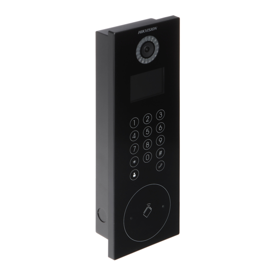
Video Intercom Door Station·Quick Start Guide IR Emission IR Receiver Loudspeaker TAMPER 1.2 Appearance of DS-KD8002-VM Figure 1-3 Front View Figure 1-4 Side View Table 1-2 Descriptions of Keys Description Low Illumination Supplement Light Built-in Camera LCD Display Screen Card Induction Area Loudspeaker Keypad... -
Page 12: Appearance Of Ds-Kd6002-Vm
Video Intercom Door Station·Quick Start Guide Call Button Microphone Call Center Key TAMPER 1.3 Appearance of DS-KD6002-VM Figure 1-5 Front View Figure 1-6 Rear View Table 1-3 Descriptions Keys Description Low Illumination Supplement Light Built-in Camera Loudspeaker... - Page 13 Video Intercom Door Station·Quick Start Guide Description LCD Display Screen Card Induction Area Keypad Call Button Call Center Key Microphone TAMPER...
-
Page 14: Terminals And Interfaces
Video Intercom Door Station·Quick Start Guide 2 Terminals and Interfaces 2.1 Terminals and Interfaces of DS-KD8102-V/ DS-KD8002-VM Figure 2-1 Terminals and Interfaces of DS-KD8102-V/DS-KD8002-VM Table 2-1 Descriptions of Terminals and Interfaces Name Interface Description USB Interface LAN1 Network Interface LAN2 Analog Interface Power DC 12V... - Page 15 Video Intercom Door Station·Quick Start Guide Name Interface Description Card Reader Indicator Output (Invalid Card Output) Card Reader Indicator Output (Valid Card Output) TAMP Tamper-proof Input of Wiegand Card Reader AO2- Alarm Relay Output 2 AO2+ ALARM AO1- Alarm Relay Output 1 AO1+ Alarm Input 4 Alarm Input 3...
-
Page 16: Terminals And Interfaces Of Ds-Kd6002-Vm
Video Intercom Door Station·Quick Start Guide 2.2 Terminals and Interfaces of DS-KD6002-VM Figure 2-2 Terminals and Interfaces of DS-KD6002-VM Table 2-2 Descriptions of Terminals and Interfaces Name Interface Description USB Interface LAN1 Network Interface LAN2 Analog Interface Power DC 12V DC 12V Power Supply Input Supply Card Reader Power Supply Output... - Page 17 Video Intercom Door Station·Quick Start Guide Name Interface Description AO2- Alarm Relay Output 2 AO2+ ALARM AO1- Alarm Relay Output 1 AO1+ Grounding Serial Port Debugging/Receive data DEBUG Serial Port Debugging/Send data 3.3V Serial Port Debugging/Power Supply Door Lock Power Supply Output Grounding Door Lock Relay Output/Connect Electric Bolt or Magnetic Lock...
-
Page 18: Installation And Wiring
Video Intercom Door Station·Quick Start Guide 3 Installation and Wiring Before you start: Make sure the device in the package is in good condition and all the assembly parts are included. The power supply the door station supports is 12 VDC. Please make sure your power supply matches your door station. -
Page 19: Wall Mounting With Gang Box Of Ds-Kd8102-V
Video Intercom Door Station·Quick Start Guide The dimension of gang box for model DS-KD8102-V door station is: 404 (length)×123 (width)×47.5 (depth) mm. The dimensions above are for reference only. The actual size can be slightly different from the theoretical dimension. 3.1.2 Wall Mounting with Gang Box of DS-KD8102-V Steps: 1. - Page 20 Video Intercom Door Station·Quick Start Guide Figure 3-4 Install the Door Station 5. Pull the door station downward and then push it towards the inside to make sure it fits the hole. 6. Tighten the screws of the door station with the Allen wrench. Figure 3-5 Tighten the Screws of Device...
-
Page 21: Installation Of Ds-Kd8002-Vm
Video Intercom Door Station·Quick Start Guide 3.2 Installation of DS-KD8002-VM 3.2.1 Gang Box for DS-KD8002-VM 407.5 Figure 3-6 Front View Figure 3-7 Overhead (Plan) View The dimension of gang box for model DS-KD8002-VM door station is: 407.5 mm × 135 mm ×... - Page 22 Video Intercom Door Station·Quick Start Guide 135.5 8.75 8.75 Figure 3-8 Dimensions of the Hole 2. Insert the gang box into the hole and fix it with 4 PA4 screws. Figure 3-9 Insert the Gang Box into the Wall 3. Make sure the edges of the gang box align to the wall and the hook A and hook B of the gang box hook onto the wall.
- Page 23 Video Intercom Door Station·Quick Start Guide Figure 3-10 Install the Door Station 7. After fixing the door station onto the gang box, secure it by inserting the plate and insert 2 POM2 screws. Figure 3-11 Secure the Door Station...
-
Page 24: Installation Of Ds-Kd6002-Vm
Video Intercom Door Station·Quick Start Guide 3.3 Installation of DS-KD6002-VM 3.3.1 Gang Box for DS-KD6002-VM Figure 3-12 Front and Side View The dimension of gang box for model DS-KD6002-VM door station is: 343(length)× 113(width)×55(depth) mm. The dimensions above are for reference only. The actual size can be slightly different from the theoretical dimension. - Page 25 Video Intercom Door Station·Quick Start Guide Screw Screw Figure 3-13 Insert the Gang Box into the Wall 3. Make sure the edges of the gang box align to the wall. 4. Route the cables of the door station through the cable hole. 5.
-
Page 26: Wiring Description
Video Intercom Door Station·Quick Start Guide Figure 3-15 Tighten the Screws of Device 3.4 Wiring Description 3.4.1 Door Lock Wiring Figure 3-16 Door Lock Wiring Terminal NO1/COM1 is set as default for accessing magnetic lock/electric bolt; terminal NC1/COM1 is set as default for accessing electric strike. -
Page 27: Door Magnetic Wiring
Video Intercom Door Station·Quick Start Guide To connect electric lock in terminal NO2/COM2/NC2, it is required to set the output of terminal NO2/COM2/NC2 to be electric lock with Batch Configuration Tool or iVMS-4200. 3.4.2 Door Magnetic Wiring Door Magnetic Wiring for DS-KD8102-V/DS-KD8002-VM For DS-KD8102-V/DS-KD8002-VM, there are two optional ways of door magnetic wiring. -
Page 28: Exit Button Wiring
Video Intercom Door Station·Quick Start Guide Terminal S2 is set as default for connecting door magnetic. Door Magnetic Wiring for DS-KD6002-VM Figure 3-19 Door Magnetic Wiring for DS-KD6002-VM To connect the door magnetic, it is required to set the output of terminal AI2 to be door magnetic with Batch Configuration Tool or iVMS-4200. - Page 29 Video Intercom Door Station·Quick Start Guide To connect the exit button, it is required to set the output of terminal AI1 to be exit button with Batch Configuration Tool or iVMS-4200. Figure 3-21 Exit Button Wiring for DS-KD8102-V/DS-KD8002-VM (2) Exit Button Wiring for DS-KD6002-VM Figure 3-22 Exit Button Wiring for DS-KD6002-VM Terminal S1 is set as default for connecting exit button.
-
Page 30: External Card Reader Wiring
Video Intercom Door Station·Quick Start Guide 3.4.4 External Card Reader Wiring Please set the DIP switch first before connecting the card reader. If the DIP switch should be configured when the card reader is power-on, please reboot the card reader after configuring the DIP switch. ... -
Page 31: Alarm Device Input Wiring
Video Intercom Door Station·Quick Start Guide Wiegand Card Reader Wiring Figure 3-24 External Card Reader Wiring 3.4.5 Alarm Device Input Wiring Alarm Device Input Wiring for DS-KD8102-V/DS-KD8002-VM Figure 3-25 Alarm Device Input Wiring for DS-KD8102-V/DS-KD8002-VM... -
Page 32: Alarm Device Output Wiring
Video Intercom Door Station·Quick Start Guide Alarm Device Input Wiring for DS-KD6002-VM Figure 3-26 Alarm Device Input Wiring for DS-KD6002-VM 3.4.6 Alarm Device Output Wiring Alarm Device Output Wiring for DS-KD8102-V Figure 3-27 Alarm Device Output Wiring for DS-KD8102-V/DS-KD8002-VM... - Page 33 Video Intercom Door Station·Quick Start Guide Alarm Device Output Wiring for DS-KD6002-VM Figure 3-28 Alarm Device Output Wiring for DS-KD6002-VM...
-
Page 34: Before You Start
Video Intercom Door Station·Quick Start Guide 4 Before You Start For the first time use of the device, you are required to activate the device and set the device password. You can activate the device via internet with Batch Configuration Tool, or with iVMS-4200 client software. -
Page 35: Local Operation
Video Intercom Door Station·Quick Start Guide 5 Local Operation Key descriptions of door stations are illustrated in the table below. ▲ The number key 2 ▼ The number key 8 ◄ The number key 4 ► The number key 6 Call Key (When calling residents or center) Delete Return... -
Page 36: Editing Network Parameters
Video Intercom Door Station·Quick Start Guide Figure 5-2 Set Password 3. Enter a new password, and confirm the password. 4. Press the # key to complete the activation. 5.2 Editing Network Parameters Purpose: Network connection is mandatory for the use of door station. Steps: 1. -
Page 37: Changing Password
Video Intercom Door Station·Quick Start Guide Figure 5-4 Network Configuration Interface 2) Press the # key to enter the network parameters settings interface. Figure 5-5 Network Parameters Settings Interface 3. Edit network parameters. 1) Move the cursor to parameters to be configured. 2) Press the # key to enter or exit the editing mode. - Page 38 Video Intercom Door Station·Quick Start Guide Figure 5-6 Admin Password Interface The default admin password is 888999. 2. Enter the password settings interface. 1) Press the number keys 4 and 6 to switch to the password settings interface Figure 5-7 Password Settings Interface 2) Press the # key to enter the password changing interface.
-
Page 39: Calling Resident
Video Intercom Door Station·Quick Start Guide 4. Press the * key to exit the network configuration interface after changing the password. 5.4 Calling Resident You can call residents via the door station. The door station can work as main/sub door station, and outer door station, which correspond to different calling resident modes respectively. - Page 40 Video Intercom Door Station·Quick Start Guide Unlocking Door by Card Before you start: Make sure the card has been issued. You can issue the card via the door station, or via iVMS-4200 client software. Please refer to User Manual for detail steps. Steps: Swipe the card on the card induction area to unlock the door.
-
Page 41: Remote Operation Via Batch Configuration Software
Video Intercom Door Station·Quick Start Guide 6 Remote Operation via Batch Configuration Software 6.1 Activating Device Remotely Purpose: You are required to activate the device first by setting a strong password for it before you can use the device. Activation via Batch Configuration Tool, and Activation via iVMS-4200 are supported. Here take activation via Batch Configuration Tool as example to introduce the device activation. -
Page 42: Editing Network Parameters
Video Intercom Door Station·Quick Start Guide STRONG PASSWORD RECOMMENDED– We highly recommend you create a strong password of your own choosing (Using a minimum of 8 characters, including at least three of the following categories: upper case letters, lower case letters, numbers, and special characters.) in order to increase the security of your product. -
Page 43: Adding Device
Video Intercom Door Station·Quick Start Guide Figure 6-4 Editing Network Parameters The default port No. is 8000. After editing the network parameters of device, you should add the devices to the device list again. 6.3 Adding Device For batch configuration tool and iVMS-4200 software, you should add device to the software so as to configure the device remotely. -
Page 44: Adding By Ip Address
Video Intercom Door Station·Quick Start Guide Figure 6-6 Login Dialog Box 3. Enter the user name and password. 4. Click the OK button to save the settings. Only devices successfully logged in will be added to the device list for configuration. ... - Page 45 Video Intercom Door Station·Quick Start Guide Figure 6-8 Adding by IP Address 4. Click the OK button to add the device to the device list. You cannot add the device(s) to the device list if the user name and password are not identical.
-
Page 46: Appendix
Video Intercom Door Station·Quick Start Guide Appendix Installation Notice While installing the indoor station, make sure that the distance between any two devices is far enough to avoid the howling and echo. The distance between two devices is recommended to be longer than 10 meters. Here devices refer to indoor station, outdoor station and master station. - Page 47 Video Intercom Door Station·Quick Start Guide...