HIKVISION D Series User Manual
Video intercom door station
Hide thumbs
Also See for D Series:
- User manual (80 pages) ,
- Quick start manual (47 pages) ,
- Manual (4 pages)
Table of Contents
Advertisement
Quick Links
Advertisement
Table of Contents

Related Manuals for HIKVISION D Series


Summary of Contents for HIKVISION D Series
- Page 1 Video Intercom Door Station (D Series) User Manual...
- Page 2 Trademarks and other Hikvision marks are the property of Hikvision and are registered trademarks or the subject of applications for the same by Hikvision and/or its affiliates. Other trademarks mentioned in this manual are the properties of their respective owners. No right of license is given to use such trademarks without express permission.
- Page 3 Video Intercom Door Station·User Manual SOME JURISDICTIONS DO NOT ALLOW THE EXCLUSION OR LIMITATION OF LIABILITY OR CERTAIN DAMAGES, SO SOME OR ALL OF THE ABOVE EXCLUSIONS OR LIMITATIONS MAY NOT APPLY TO YOU. Support Should you have any questions, please do not hesitate to contact your local dealer.
- Page 4 Video Intercom Door Station·User Manual Regulatory Information FCC Information Please take attention that changes or modification not expressly approved by the party responsible for compliance could void the user’s authority to operate the equipment. FCC compliance: This equipment has been tested and found to comply with the limits for a Class B digital device, pursuant to part 15 of the FCC Rules.
- Page 5 Video Intercom Door Station·User Manual 2006/66/EC (battery directive): This product contains a battery that cannot be disposed of as unsorted municipal waste in the European Union. See the product documentation for specific battery information. The battery is marked with this symbol, which may include lettering to indicate cadmium (Cd), lead (Pb), or mercury (Hg).
- Page 6 Video Intercom Door Station·User Manual Safety Instruction These instructions are intended to ensure that user can use the product correctly to avoid danger or property loss. The precaution measure is divided into Warnings and Cautions: Warnings: Neglecting any of the warnings may cause serious injury or death. Cautions: Neglecting any of the cautions may cause injury or equipment damage.
- Page 7 Video Intercom Door Station·User Manual Model Manufacturer Standard DSA-12PFG-12 FUK 120100 Dee Van Electronics Co., Ltd. DSA-12PFG-12 FAU 120100 Dee Van Electronics Co., Ltd. Cautions Do not drop the device or subject it to physical shock, and do not expose it to high electromagnetism radiation.
-
Page 8: Table Of Contents
Video Intercom Door Station·User Manual Table of Contents 1 Overview ...................... 1 1.1 Introduction ......................1 1.2 Main Features ......................1 2 Appearance ....................2 2.1 Appearance of DS-KD8102-V ................... 2 2.2 Appearance of DS-KD8002-VM ................3 2.3 Appearance of DS-KD3002-VM ................4 3 Typical Application .................. - Page 9 Video Intercom Door Station·User Manual 6.4.5 Set Volume ...................... 36 6.4.6 About ....................... 37 6.4.7 Change System Language ................. 37 6.4.8 Open Source Software Licenses ..............38 6.5 Call Resident ......................38 6.6 Unlock Door ......................39 7 Remote Operation via Batch Configuration Tool ......... 40 7.1 Activate Device Remotely ..................
-
Page 10: Overview
Video Intercom Door Station·User Manual 1 Overview 1.1 Introduction The video intercom system can realize functions such as video intercom, resident-to-resident video call, live view of HD video, access control, one-card system, elevator linkage, 8-ch zone alarm, notice information and visitor messages to provide a complete smart community video intercom solution. -
Page 11: Appearance
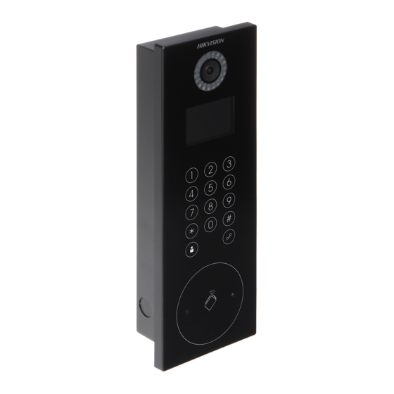
Video Intercom Door Station·User Manual 2 Appearance 2.1 Appearance of DS-KD8102-V Table 2-1 Descriptions of Keys Description Low Illumination Supplement Light Built-in Camera LCD Display Screen Keypad Call Button Call Center Key Microphone Card Induction Area IR Emission IR Receiver... -
Page 12: Appearance Of Ds-Kd8002-Vm
Video Intercom Door Station·User Manual Loudspeaker TAMPER 2.2 Appearance of DS-KD8002-VM Table 2-2 Descriptions of Keys Description Low Illumination Supplement Light Built-in Camera LCD Display Screen Card Induction Area Loudspeaker Keypad Call Button Microphone Call Center Key TAMPER... -
Page 13: Appearance Of Ds-Kd3002-Vm
Video Intercom Door Station·User Manual 2.3 Appearance of DS-KD3002-VM Table 2-3 Descriptions of Keys Description Low Illumination Supplement Light Built-in Camera Loudspeaker LCD Display Screen Card Induction Area Keypad Call Button Call Center Key Microphone TAMPER... -
Page 14: Typical Application
Video Intercom Door Station·User Manual 3 Typical Application PC Client A Building Indoor Indoor Extension2 Extension1 Resident 2 Resident 1 Center Master Station Resident 2 Resident 1 Master Station (Guarding Room) Resident 2 Resident 1 Network Camera Elevator Controller Card Reader Outer Door Station Card Reader Door Station... -
Page 15: Terminal And Wiring
Video Intercom Door Station·User Manual 4 Terminal and Wiring 4.1 Terminal Description 4.1.1 Terminals and Interfaces of DS-KD8102-V/ DS-KD8002-VM Table 4-1 Descriptions of Terminals and Interfaces Name Interface Description USB Interface LAN1 Network Interface LAN2 Analog Interface Power DC 12V DC 12V Power Supply Input Supply Power Supply Output... - Page 16 Video Intercom Door Station·User Manual Name Interface Description Output) Card Reader Indicator Output (Valid Card Output) TAMP Tamper-proof Input of Wiegand Card Reader AO2- Alarm Relay Output 2 AO2+ ALARM AO1- Alarm Relay Output 1 AO1+ Alarm Input 4 Alarm Input 3 ALARM IN Alarm Input 2 Alarm Input 1...
-
Page 17: Terminals And Interfaces Of Ds-Kd3002-Vm
Video Intercom Door Station·User Manual 4.1.2 Terminals and Interfaces of DS-KD3002-VM Table 4-2 Descriptions of Terminals and Interfaces Name Interface Description USB Interface LAN1 Network Interface LAN2 Analog Interface Power DC 12V DC 12V Power Supply Input Supply Power Supply Output Grounding Data Input Interface Wiegand Card Reader: Data1... - Page 18 Video Intercom Door Station·User Manual Name Interface Description AO1- Alarm Relay Output 1 AO1+ Grounding Serial Port Debugging/Receive data DEBUG Serial Port Debugging/Send data 3.3V Serial Port Debugging/Power Supply Power Supply Output Grounding Door Lock Relay Output (NC) COM2 Grounding Signal DOOR Door Lock Relay Output (NO) Door Lock Relay Output (NC)
-
Page 19: Wiring Description
Video Intercom Door Station·User Manual 4.2 Wiring Description 4.2.1 Door Lock Wiring Terminal NC1/COM1 is set as default for accessing magnetic lock/electric bolt; terminal NO1/COM1 is set as default for accessing electric strike. To connect electric lock in terminal NO2/COM2/NC2, it is required to set the output of terminal NO2/COM2/NC2 to be electric lock with Batch Configuration Tool or iVMS-4200. - Page 20 Video Intercom Door Station·User Manual To connect the door magnetic, it is required to set the output of terminal AI2 to be door magnetic with Batch Configuration Tool or iVMS-4200. Door Magnetic Wiring for DS-KD8102-V/DS-KD8002-VM (2) Terminal S2 is set as default for connecting door magnetic. Door Magnetic Wiring for DS-KD3002-VM...
-
Page 21: Exit Button Wiring
Video Intercom Door Station·User Manual To connect the door magnetic, it is required to set the output of terminal AI2 to be door magnetic with Batch Configuration Tool or iVMS-4200. 4.2.3 Exit Button Wiring Exit Button Wiring for DS-KD8102-V/DS-KD8002-VM For DS-KD8102-V/DS-KD8002-VM, there are two optional ways of exit button wiring. Exit Button Wiring for DS-KD8102-V/DS-KD8002-VM (1) To connect the exit button, it is required to set the output of terminal AI1 to be exit button with Batch Configuration Tool or iVMS-4200. -
Page 22: External Card Reader Wiring
Video Intercom Door Station·User Manual Exit Button Wiring for DS-KD3002-VM Terminal S1 is set as default for connecting exit button. 4.2.4 External Card Reader Wiring Please set the DIP switch first before connecting the card reader. If the DIP switch should be configured when the card reader is power-on, please reboot the card reader after configuring the DIP switch. - Page 23 Video Intercom Door Station·User Manual RS-485 Card Reader Wiring Wiegand Card Reader Wiring...
-
Page 24: External Elevator Controller Wiring
Video Intercom Door Station·User Manual 4.2.5 External Elevator Controller Wiring You can connect the door station to the elevator controller via RS-485 interface. There are 4 groups of RS-485 interfaces on the elevator controller: group A, group B, Group C, and Group D. Group C is used to connect to the door station. 4.2.6 Alarm Device Input Wiring Alarm Device Input Wiring for DS-KD8102-V... -
Page 25: Alarm Device Output Wiring
Video Intercom Door Station·User Manual Alarm Device Input Wiring for DS-KD3002-VM 4.2.7 Alarm Device Output Wiring Alarm Device Output Wiring for DS-KD8102-V/DS-KD8002-VM... - Page 26 Video Intercom Door Station·User Manual Alarm Device Output Wiring for DS-KD3002-VM...
-
Page 27: Installation
Video Intercom Door Station·User Manual 5 Installation Before you start: Make sure the device in the package is in good condition and all the assembly parts are included. The power supply the door station supports is 12 VDC. Please make sure your power supply matches your door station. -
Page 28: Wall Mounting With Gang Box Of Ds-Kd8102-V
Video Intercom Door Station·User Manual The dimension of gang box for model DS-KD8102-V door station is: 404 (length)×123 (width)×47.5 (depth) mm. The dimensions above are for reference only. The actual size can be slightly different from the theoretical dimension. 5.1.2 Wall Mounting with Gang Box of DS-KD8102-V Steps: 1. - Page 29 Video Intercom Door Station·User Manual 5. Pull the door station downward and then push it towards the inside to make sure it fits the hole. 6. Tighten the screws of the door station with the Allen wrench.
-
Page 30: Installation Of Ds-Kd8002-Vm
Video Intercom Door Station·User Manual 5.2 Installation of DS-KD8002-VM 5.2.1 Gang Box for DS-KD8002-VM 407.5 The dimension of gang box for model DS-KD8002-VM door station is: 407.5 mm × 135 mm × 55 mm. The dimensions above are for reference only. The actual size can be slightly larger than the theoretical dimension. - Page 31 Video Intercom Door Station·User Manual 135.5 8.75 8.75 2. Insert the gang box into the hole and fix it with 4 PA4 screws. 3. Make sure the edges of the gang box align to the wall and the hook A and hook B of the gang box hook onto the wall.
- Page 32 Video Intercom Door Station·User Manual 7. After fixing the door station onto the gang box, secure it by inserting the plate and insert 2 POM2 screws.
-
Page 33: Installation Of Ds-Kd3002-Vm
Video Intercom Door Station·User Manual 5.3 Installation of DS-KD3002-VM 5.3.1 Gang Box for DS-KD3002-VM The dimension of gang box for model DS-KD3002-VM door station is: 343(length)× 113(width)×55(depth) mm. The dimensions above are for reference only. The actual size can be slightly different from the theoretical dimension. - Page 34 Video Intercom Door Station·User Manual Screw Screw 3. Make sure the edges of the gang box align to the wall. 4. Route the cables of the door station through the cable hole. 5. Put the door station into the gang box. 6.
- Page 35 Video Intercom Door Station·User Manual...
-
Page 36: Local Operation
Video Intercom Door Station·User Manual 6 Local Operation 6.1 Keys Description Key descriptions of door stations are illustrated in Table 6-1. Table 6-1 Key Descriptions Description Numeric Key 2 ▲ Numeric Key 4 ▼ Numeric Key 6 ◄ Numeric Key 8 ►... - Page 37 Video Intercom Door Station·User Manual 3. Enter a new password, and confirm the password. The character description for each numeric key is shown in Table 6-2. Table 6-2 Character Description Description Description 1,.?!*#- 6mnoMNO 2abcABC 7pqrsPQRS 3defDEF 8tuvTUV 4ghiGHI 9wxyzWXYZ 5jklJKL When entering the password, taking the numeric key 2 as example, press the numeric key 2 once, the text field shows "2", and press it again, the text field shows...
-
Page 38: Status
Video Intercom Door Station·User Manual 6.3 Status The door station can display different status with icons in Table 6-3. Table 6-3 Icon Description Icon Description Please check the network cable of the door station. Invalid SIP server IP address. Set the SIP server IP address. -
Page 39: Set Door Station No
Video Intercom Door Station·User Manual The default admin password is 888999. Under the configuration mode, press the number key 2 and 8 to switch the parameter interfaces. 6.4.1 Set Door Station No. For the local settings, you can set the door station No. such as community No., building No., floor No., and so on. -
Page 40: Edit Network Parameters
Video Intercom Door Station·User Manual Device No. Settings Interface (Door Device No. Settings Interface (Outer Door Station) Station) 2. Edit parameters. 1) Move the cursor to parameters to be configured. 2) Press the # key to enter the editing mode, and input numbers. 3) Press the # key to exit the editing mode. -
Page 41: Change Password
Video Intercom Door Station·User Manual With the private SIP protocol, you should set IP address, sub mask, gateway, SIP IP, master IP, and center IP for the door station. Network Parameters Settings Interface (private SIP) With the standard SIP protocol, you should set IP address, sub mask, gateway, and center IP. - Page 42 Video Intercom Door Station·User Manual The default configuration password is 888999. We recommend you reset your password regularly, especially in the high security system, resetting the password monthly or weekly can better protect your product. Press the numeric keys 4 and 6 to switch to the password settings interface. Change Configuration Password Steps: 1.
-
Page 43: Issue Card
Video Intercom Door Station·User Manual 2. Enter the old password, and the new password, and confirm the new one. 3) Move the cursor to parameters to be configured. 4) Press the # key to enter or exit the editing mode. 3. - Page 44 If the main card is invalid, it prompts the message: Incorrect Main Card. For the door station (D series), if the amount of sub cards exceeds 2500, no more sub card can be issued and the station prompts the message: No more sub card can be issued.
-
Page 45: Set Volume
4. Press the * key to exit the card issuing interface. For the door station (D series), if the amount of sub cards exceeds 2500, no more sub card can be issued and the station prompts the message: No more sub card can be issued. -
Page 46: About
Video Intercom Door Station·User Manual 2) Press the # key to enter the volume parameters settings interface. 2. Set the volume. 1) Move the cursor to parameters to be configured. 2) Press the # key to enter or exit the editing mode. 3. -
Page 47: Open Source Software Licenses
Video Intercom Door Station·User Manual 6.4.8 Open Source Software Licenses On the settings interface, press numeric keys 4 and 6 to switch to the Open Source Software interface, and press the # key to open source software licenses of the device. 6.5 Call Resident You can call residents via the door station no matter the door station is in the network intercom system or the analog intercom system. -
Page 48: Unlock Door
Video Intercom Door Station·User Manual With the standard SIP protocol, the calling No. should be the VoIP phone No. of the indoor station. And you must make sure that the indoor station supports the standard SIP protocol. 2. Press the key to start calling the resident. -
Page 49: Remote Operation Via Batch Configuration Tool
Video Intercom Door Station·User Manual 7 Remote Operation via Batch Configuration Tool You can configure and operate the video intercom devices via Batch Configuration Tool. Default parameters of door station are as follows: Default IP Address: 192.0.0.65. Default Port No.: 8000. ... -
Page 50: Edit Network Parameters
Video Intercom Door Station·User Manual STRONG PASSWORD RECOMMENDED– We highly recommend you create a strong password of your own choosing (Using a minimum of 8 characters, including at least three of the following categories: upper case letters, lower case letters, numbers, and special characters.) in order to increase the security of your product. -
Page 51: Add Device
Video Intercom Door Station·User Manual The default port No. is 8000. The default IP address of the door station is 192.0.0.65. After editing the network parameters of device, you should add the devices to the device list again. ... -
Page 52: Add By Ip Address
Video Intercom Door Station·User Manual 2. Click the button to pop up the login dialog box. 3. Enter the user name and password. 4. Click the OK button to save the settings. Only devices successfully logged in will be added to the device list for configuration. ... -
Page 53: Add By Ip Segment
Video Intercom Door Station·User Manual 4. Click the OK button to add the device to the device list. You cannot add the device(s) to the device list if the user name and password are not identical. When you add devices by IP Address, IP Segment or Port No., the devices should be online devices. -
Page 54: Configure Devices Remotely
Video Intercom Door Station·User Manual 5. Click the OK button to search and add the devices whose IP addresses are within the range of the defined IP segment to the device list. 7.4 Configure Devices Remotely In the device list area, select a device and click to enter the remote configuration interface. - Page 55 Video Intercom Door Station·User Manual Time Steps: 1. Click Time to enter the device time settings interface. 2. Select Time Zone or Enable NTP. Time Zone Select a time zone from the drop-down list menu. Click Synchronization. Check the checkbox of Enable NTP to enable NTP. Enter the server address, NTP port, and synchronization interval.
- Page 56 Video Intercom Door Station·User Manual System Maintenance Purpose: You can operate the system management and remote upgrading, and change system language on the system maintenance interface. Steps: 1. Click System Maintenance to enter the system maintenance interface. 2. Click Reboot and the system reboot dialog box pops up. Click Yes to reboot the system.
- Page 57 Video Intercom Door Station·User Manual Click Restore All button, all default settings, including network parameters, will be restored. The device will be reset to inactivated status. 5. Click Import Configuration File and the import file window pops up. Select the path of remote configuration files.
- Page 58 Video Intercom Door Station·User Manual 8. Select a language and click Save to change the system language. User Purpose: You can edit the password for logging in the device. Steps: 1. Click the User button to enter the user information editing interface. 2.
- Page 59 Video Intercom Door Station·User Manual 3. Enter the new password, and confirm it.
-
Page 60: Video Intercom
Video Intercom Door Station·User Manual STRONG PASSWORD RECOMMENDED– We highly recommend you create a strong password of your own choosing (Using a minimum of 8 characters, including at least three of the following categories: upper case letters, lower case letters, numbers, and special characters.) in order to increase the security of your product. - Page 61 3. Click Save to enable the device number configuration. For main door station (D series or V series), the serial No. is 0. For sub door station (D series or V series), the serial No. is higher than 0. Serial No. ranges from 1 to 99.
- Page 62 Video Intercom Door Station·User Manual Password Click Password to enter password changing interface. You can modify the admin password (also called configuration password), public password, and card activation password. Configuration Password (Admin Password): It is necessary when you want to configure parameters of the door station, such as IP parameters, door station No., system type, and so on.
- Page 63 Video Intercom Door Station·User Manual 3. (Optional) Enable Delay Door Alarm. 4. Click Save to enable the settings. The door-unlocked duration ranges from 1s to 225s. If you check Delayed Door Alarm, an alarm will be triggered automatically if the door is not locked in the configured duration.
- Page 64 2. Select I/O input No., input mode, output No., and output mode. 3. Click Save to enable the settings. For door station (D series), there are 8 I/O Input Terminals. Terminal 1~4 correspond to SENSOR interfaces (S1, S2, S3, S4) of door station. Terminal 5~8 correspond to interfaces of ALARM IN (A1, A2, A3, A4).
-
Page 65: Network
Video Intercom Door Station·User Manual Intercom Protocol Door station supports the private SIP protocol and the standard SIP protocol. You can change the protocol in the Intercom Protocol interface. Step: 1. Click Intercom Protocol to enter the intercom protocol interface. 2. - Page 66 Video Intercom Door Station·User Manual SIP Configuration A SIP server connection is required and necessary for the door station to guarantee the connection between the door station and the management center (master station) in the same video intercom system. 2 types of SIP protocol are available for the door station: Private Protocol, and Standard Protocol.
- Page 67 Video Intercom Door Station·User Manual 2. Enter the master station IP address, (main) door station IP address, SIP server IP address, management center IP address, and doorphone IP address. 3. Select the main door station type from the drop-down list. 4.
- Page 68 Video Intercom Door Station·User Manual 2. Check the checkbox of Enable Main FTP. 3. Select IP address from the drop-down list of server mode. 4. Enter the FTP server address, and port No. 5. Check the checkbox to enable the anonymity (optional). 6.
-
Page 69: Video Display
Video Intercom Door Station·User Manual 2. Enter the DNS server addresses. 3. Click the Save button to enable the advanced network settings. Video Display 7.4.4 Steps: 1. Click the Video Display button to enter the video parameters interface. 2. Select the camera No. 3. -
Page 70: Video Intercom Device Set-Up Tool
Video Intercom Door Station·User Manual Click the Restore Default Settings button to restore all parameters excluding network parameters to the factory settings. 7.5 Video Intercom Device Set-up Tool Purpose: You can assign the device to the community, activate and set the device, and configure the network parameters and linked network parameters for the device by using the video intercom device set-up tool. -
Page 71: Set Main/Sub Door Station
Video Intercom Door Station·User Manual Set Main/Sub Door Station 7.5.2 Set Main Door Station Purpose: You can activate the online main door station, and configure the building No. for the online main door station. Steps: 1. Select the community, and press the Main Door Station tab to switch to the main door station configuration interface. - Page 72 Video Intercom Door Station·User Manual The default main door station floor No. is 1. For the login password, if the main door station has been activated, enter the activation password here. If the main door station is not activated, create a login password here, and the main door station will be activated simultaneously.
-
Page 73: Batch Upgrading
Video Intercom Door Station·User Manual 4. Set the linked network parameters for the sub door station: main door station IP address, SIP IP address, master station IP address, center IP address, center port No., subnet mask, and gateway address. 5. Select an online door station, enter the login password, and click the Set button. ... - Page 74 Video Intercom Door Station·User Manual Add Online Device Steps: 1. In the batch upgrading interface, click the to open the online device window. 2. Select a device, enter the user name and password, and click the Login Device button. 3. Click the Add Device button, and the device is added to the batch upgrading tool.
- Page 75 Video Intercom Door Station·User Manual Add by IP Address/IP Segment Steps: 1. Click the Manual button to open the device adding window. 2. Enter the corresponding information (IP address, user name, password, start IP address, end IP address). 3. Click the Add button.
-
Page 76: Upgrade Devices
Video Intercom Door Station·User Manual Upgrade Devices 7.6.2 Door station supports upgrading by file. Upgrading by File: You upgrade the device or devices via the local upgrade files. Steps: 1. Select a device or multiple devices, and select “Upgrade by File” as the upgrading mode. -
Page 77: Remote Operation Via Ivms-4200
Video Intercom Door Station·User Manual 8 Remote Operation via iVMS-4200 The Video Intercom module provides remote control and configuration on video intercom products via the iVMS-4200 client software. 8.1 System Configuration Purpose: You can configure the video intercom parameters accordingly. Steps: 1. -
Page 78: Device Management
Video Intercom Door Station·User Manual 8.2 Device Management Purpose: Device management includes device activation, adding device, editing device, and deleting device, and so on. After running the iVMS-4200, video intercom devices should be added to the client software for remote configuration and management. 8.2.1 Add Video Intercom Devices ... - Page 79 Device Management page. 2. Click Device. 3. On the Device Type panel on the right, you can select Hikvision Device to add video intercom devices. 4. The active online devices in the same local subnet with the client software will be displayed on the Online Device area.
-
Page 80: Modify Network Information
Video Intercom Door Station·User Manual Add Multiple Online Devices If you want to add multiple online devices to the client software, click and hold Ctrl key to select multiple devices, and click Add to Client to open the device adding dialog box. In the pop-up message box, enter the user name and password for the devices to be added. -
Page 81: Reset Password
Video Intercom Door Station·User Manual You should enter the admin password of the device in the Password field of the pop-up window to modify the parameters. 8.2.3 Reset Password According to the different video intercom devices, the software provides two different methods for restoring the default password or resetting the password. - Page 82 Video Intercom Door Station·User Manual 1. Click Export to save the device file on your computer. 2. Send the file to our technical engineers. 3. Our technical engineer will send you a file to you. After receiving a file from the technical engineer, select Import File from Key Importing Mode drop-down list and click to import the file.
-
Page 83: Remote Configuration
Video Intercom Door Station·User Manual 1. Click Export to save the device file on your computer. 2. Send the file to our technical engineers. 3. Click Import and select the file received from the technical engineer. 4. Input new password in text fields of Password and Confirm Password. 5. - Page 84 Video Intercom Door Station·User Manual For the first time opening the Access Control module, the following dialog will pop up and you are required to select the scene according to the actual needs. You can select the scene as Non-residence and Residence. Once the scene is configured, you cannot change it later.
-
Page 85: Organization Management
Video Intercom Door Station·User Manual person to the organization and issue card to persons for further management. 8.4.1 Organization Management Add Organization Steps: In the organization list on the left, you should add a top organization as the parent organization of all organizations. Click Add button to pop up the adding organization interface. -
Page 86: Person Management
Video Intercom Door Station·User Manual 8.4.2 Person Management After adding the organization, you can add person to the organization and manage the added person such as issuing cards in batch, importing and exporting person’s information in batch, etc. Up to 10,000 persons or cards can be added. Add Person Person information is necessary for the video intercom system. - Page 87 Video Intercom Door Station·User Manual Set basic person information. Enter basic information: person name, gender, phone No., birthday details, and email address. (Optional) Click Upload Picture to select the person picture from the local PC to upload it to the client. The picture should be in *.jpg format.
- Page 88 Video Intercom Door Station·User Manual Click Add to pop up the Add Card dialog. Select Normal Card. Enter the password of the card itself in the Card Password field. The card password should contain 4 to 8 digits. Enter Card Number manually. Click OK and the card(s) will be issued to the person.
- Page 89 Video Intercom Door Station·User Manual Exporting Person: You can export the added persons’ information in Excel format to the local PC. After adding the person, you can click Export Person button to pop up the following dialog. Click to select the path of saving the exported Excel file. Check the checkboxes to select the person information to export.
- Page 90 Video Intercom Door Station·User Manual Click OK to start importing. Get Person Information from Device If the added device has been configured with person information (including person details, fingerprint, issued card information), you can get the person information from the device and import to the client for further operation. This function is only supported by the device the connection mothod of which is TCP/IP when adding the device.
- Page 91 Video Intercom Door Station·User Manual Modify and Delete Person To modify the person information and attendance rule, click in the Operation column, or select the person and click Modify to open the editing person dialog. You can click to view the person’s card swiping records. To delete the person, select a person and click Delete to delete it.
-
Page 92: Video Intercom
Video Intercom Door Station·User Manual Select Normal Card. Enter the password of the card itself in the Card Password field. The card password should contain 4 to 8 digits. Enter the card quantity issued for each person. For example, if the Card Quantity is 3, you can read or enter three card No. for each person. -
Page 93: Receive Call From Indoor Station/Door Station
Video Intercom Door Station·User Manual Click -> tab on the left icon bar to enter the Video Intercom interface. 8.5.1 Receive Call from Indoor Station/Door Station Steps: Select the client software in the indoor station or door station interface to start calling the iVMS-4200 and an incoming call dialog will pop up in the client software. -
Page 94: View Live Video Of Door Station And Outer Door Station
Video Intercom Door Station·User Manual Click to adjust the volume of the loudspeaker. Click to hang up. Click to adjust the volume of the microphone. For door station, you can click to open the door remotely. One video intercom device can only connect with one client software. ... -
Page 95: View Call Logs
Video Intercom Door Station·User Manual Right click on the live view interface to display the menu and select Unlock to remote unlock the door. 8.5.3 View Call Logs Purpose:... -
Page 96: Release Notice
Video Intercom Door Station·User Manual You can check all the call logs, including dialed call logs, received call logs and missed call logs. You can also directly dial via the log list and clear the logs. Steps: In the Video Intercom page, click the Call Log tab to enter the Call Log page. All the call logs will display on this page and you can check the log information, e.g., call status, start time, resident’s organization and name, device name and ring or speaking duration. - Page 97 Video Intercom Door Station·User Manual Click New Notice on the left panel to create a new notice. Edit the notice on the right panel. Click icon on the Send To field to pop up the Select Resident dialog.
- Page 98 Video Intercom Door Station·User Manual Check the checkbox(es) to select the resident(s). Or you can check the All checkbox to select all the added residents. Click OK to save the selection. Enter the subject on the Subject field. Up to 63 characters are allowed in the Subject field. Click in the Type field to unfold the drop-down list and select the notice type.
-
Page 99: Search Video Intercom Information
Video Intercom Door Station·User Manual 8.5.5 Search Video Intercom Information Purpose: You can search the call logs between the iVMS-4200 client software and video intercom devices, device unlocking logs and the sent notice information. In the Access Control module, click icon tab to open the Search page. - Page 100 Video Intercom Door Station·User Manual Click Search and all the matched call logs will display on this page. For the search results, (Optional) Check the detailed information of searched call logs, such as call status, ring/speaking duration, device name, resident organization, etc. ...
- Page 101 Video Intercom Door Station·User Manual Start Time/End Time: Click to specify the start time and end time of a time period to search the logs. (Optional) You can click Reset to reset all the configured search conditions. Click Search and all the matched unlocking logs will display on this page. For the searching results, ...
- Page 102 Video Intercom Door Station·User Manual Notice Type: Click to unfold the drop-down list and select the notice type as Advertising Information, Property Information, Alarm Information or Notice Information. Or select All to search notices with all types. Subject: Input the keywords in the Subject field to search the matched notice. ...
-
Page 103: Appendix
Video Intercom Door Station·User Manual Appendix Installation Notice While installing the indoor station, make sure that the distance between any two devices is far enough to avoid the howling and echo. The distance between two devices is recommended to be longer than 10 meters. Here devices refer to indoor station, outdoor station and master station. - Page 104 Video Intercom Door Station·User Manual UD09693B...