Makita DUR181RT Technical Information
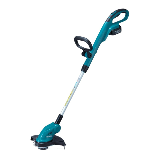
260mm (10-1/4") cordless string trimmer
Hide thumbs
Also See for DUR181RT:
- Instruction manual (97 pages) ,
- Instruction manual (17 pages) ,
- Instruction manual (93 pages)
Advertisement
Quick Links
T
ECHNICAL INFORMATION
Model No.
Description
C
ONCEPT AND MAIN APPLICATIONS
Models DUR141/ DUR181 have been developed as
lightweight 260mm (10-1/4") Cordless string trimmers for home gardening
powered by the following Li-ion batteries:
DUR141 by BL1415 (14V-1.3Ah), BL1415N (1.5Ah), BL1415NA (1.5Ah),
BL1430 (3.0Ah), BL1430A (3.0Ah), BL1440 (4.0Ah) or BL1450 (5.0Ah)
DUR181 by BL1815 (18V-1.3Ah), BL1815N (1.5Ah), BL1820 (2.0Ah),
BL1830 (3.0Ah), BL1840 (4.0Ah) or BL1850 (5.0Ah)
And they feature well balanced tool design with angle adjustable
cutting head.
S
pecification
Specification
Cell
Voltage: V
Capacity: Ah
Battery
Energy capacity: Wh
Charging time: min.
Max. output: W
Cutting width: mm (")
No load speed: min
ˉ
Cord feeding system
Cutting system
Nylon
cutting head
Nylon cord
[diameter x length]
Length adjust range of pipe shaft: mm (")
Edger function
Weight according to EPTA-Procedure
01/2003*
: kg (lbs)
2
*2 with Battery, Nylon cutting head, Shoulder strap, Guard, Loop handle
*3 with BL1415/BL1415N/BL1815/BL1815N/BL1820
*4 with BL1430/BL1440/BL1450/BL1830/BL1840/BL1850
S
tandard equipment
Nylon cutting head
Shoulder belt
*5 Battery and charger are not supplied with "Z" model.
*6 Supplied with the same quantity of extra Battery
Note: The standard equipmentmay vary by country or model variation.
O
ptional accessories
Shoulder belt
Safety goggles
15m Nylon cord
30m Nylon cord
Spool set
DUR141/ DUR181
260mm (10-1/4") Cordless String Trimmer
DUR141
Model
1.3, 1.5, 3.0, 4.0, 5.0
19, 22, 44, 58, 72
15, 15, 22, 36, 45
with DC18RC
¹=rpm
2.9 (6.3)
3.0 (6.7)
Safety goggles
Battery
15m Nylon cord
Battery cover
For DUR141
For DUR181
Battery BL1415
Battery BL1815
Battery BL1815N
Battery BL1415N
Battery BL1820
Battery BL1415NA
Battery BL1830
Battery BL1430
Battery BL1840
Battery BL1430A
Battery BL1850
Battery BL1440
Battery BL1450
PI / NP / TE
DUR181
Li-ion
14.4
18
1.3, 1.5, 2.0, 3.0, 4.0, 5.0
24, 27, 36, 54, 72, 90
15, 15, 24, 22, 36, 45
with DC18RC
160
230
260 (10-1/4)
7,800
6,000
Bump & Feed
Single cord
1.65mm x 8m (1/16" x 26ft)
190 (7-1/2)
Yes
2.9 (6.4)
*3
3.1 (6.9)
*4
Charger
*5
*5
*6
Fast charger DC18RC
Charger DC18SD
Charger DC24SC
Automotive charger DC18SE
Four port multi charger DC18SF
Two port multi fast charger DC18RD
海外営業管理承認
for ASC & Sales Shop
W
Dimensions: mm (")
minimum
Length (L)
maximum
Width (W)
minimum
Height (H)*
1
maximum
*
The height varies depending on the angle of
1
the cutting head.
*3
*4
OFFICIAL USE
PRODUCT
P 1/ 10
H
L
1,229 (48-1/2)
1,433 (56-1/2)
267 (10-1/2)
186 (7-3/8)
257 (10-1/8)
Advertisement

Related Manuals for Makita DUR181RT


Summary of Contents for Makita DUR181RT
- Page 1 PI / NP / TE OFFICIAL USE 海外営業管理承認 for ASC & Sales Shop ECHNICAL INFORMATION PRODUCT P 1/ 10 Model No. DUR141/ DUR181 Description 260mm (10-1/4") Cordless String Trimmer ONCEPT AND MAIN APPLICATIONS Models DUR141/ DUR181 have been developed as lightweight 260mm (10-1/4") Cordless string trimmers for home gardening powered by the following Li-ion batteries: DUR141 by BL1415 (14V-1.3Ah), BL1415N (1.5Ah), BL1415NA (1.5Ah),...
-
Page 2: Necessary Repairing Tools
1R286 Round Bar for Arbor 12-50 Supporting Spool holder to press-fit Gear shaft [2] LUBRICATION Apply Makita grease N. No.2 to the following portions designated with the black triangle to protect parts and product from unusual abrasion. Item No. Description... - Page 3 P 3/ 10 epair [3] DISASSEMBLY/ASSEMBLY [3] -1. Gear shaft complete (cont.) DISASSEMBLING (2) After removing Motor housing R, Remove DC motor and Gear shaft complete as drawn in Fig. 3. Fig. 3 3. Remove five 4x18 Tapping screws and 4.
- Page 4 3. Apply adhesive (ThreeBond 1342 or Locktite 242) to the thread of M4x8 Pan head screw when reusing it. Replace M4 Hex socket head bolt to M4x8 Pan head screw with adhesive. Note: Makita genuine M4x8 Pan head screw is thread locker screw. Compression spring 17 (2) Assemble Gear shaft complete to Motor housing in the reverse order of Disassembly.
- Page 5 P 5/ 10 epair [3] DISASSEMBLY/ASSEMBLY [3] -3. Pipe section DISASSEMBLING (1) Remove Spool set and Safety cover as drawn in Fig. 2. (2) Separate Motor housing (R) from Motor housing (L) as drawn in Fig. 3. (3) Disassemble Pipe 25 complete as drawn in Fig. 6. Fig.
- Page 6 P 6/ 10 epair [3] DISASSEMBLY/ASSEMBLY [3] -3. Pipe section (cont.) ASSEMBLING Assemble Pipe section as drawn in Figs. 7 and 8. Fig. 7 2. Pass Power supply cord unit through Pipe 25. 1. Insert Pipe cap into Pipe 25 so that the square Fit the square projection of Pipe cap into the inner groove of projection of Pipe cap fits in the left side of Handle (L).
-
Page 7: Circuit Diagram
P 7/ 10 ircuit diagram DUR141, DUR181 Fig. D-1 Color index of lead wires' sheath Black White Orange Yellow Handle section LED warning Lamp This Lead wire is white for some countries instead of red. Switch Pipe 25 section Terminal Controller Motor housing... -
Page 8: Iring Diagram
P 8/ 10 iring diagram DUR141, DUR181 Fig. D-2 Wiring to DC motor While facing the wire connecting portions to Motor housing (L) side, connect Lead wire (red) receptacle to the terminal with Red dot mark and Lead wire (black) receptacle to the other terminal. Flag receptacles Red dot mark Wire connecting... -
Page 9: Wiring Diagram
P 9/ 10 iring diagram DUR141, DUR181 Fig. D-4 Wiring in Pipe 25 1. Insert the long sheath side into Pipe 25 complete as drawn below. Lead wires for connecting to Controller in Handle set Long sheath Coil portion Lead wires for connecting to DC motor in Motor housing Pipe 25 complete Short... - Page 10 P 10/ 10 iring diagram DUR141, DUR181 Fig. D-5 Wiring to Terminal While facing the wire connecting portion to Pipe 25 side, connect the Lead wire Lead wire (black) to Terminal. And then, connect Lead (Yellow) wires (red, yellow) to Terminal. Lead wire Lead wire (red)