
Related Manuals for Honeywell SC1000


Summary of Contents for Honeywell SC1000
- Page 1 Sensing and Control SC Instrumentation Signal Conditioning, Self-Calibrating Digital Indicators Model SC2001 Models SC1000 & SC2000 Model SC3004 Sensotec Sensors...
- Page 2 Toll Free: 1-800-848-6564 E-mail: service@sensotec.com http://www.honeywell.com/sensing http://www.sensotec.com SC Series Instruction Manual Models SC1000, SC2000, SC2001 and SC3004 Document Number: 008-0608-00 Rev. C: February, 2005 WARNING The operator of this instrument is advised that if the equipment is used in a man- ner not specified in this manual, the protection provided by the equipment may be impaired.
-
Page 3: Table Of Contents
Contents ........Chapter 1 Introduction ....... . 1.1 About This Manual . - Page 4 4.2 Specifications ......4.3 Models SC1000 and SC2000 ....
- Page 5 8.1 Overview ....... 8.2 Menu Items for Models SC1000, SC2000, SC2001 8.2.1 UPPER CHANNEL Menu Item .
- Page 6 10.5.2 DISPLAY SETUP Sub-Menu ..... 10.5.3 AUXn FUNCTION Menu Items ....10.5.4 CALIBRATION TYPE Menu Item .
- Page 7 12.3 Excitation and Signal Jumpers ... . . 12.3.1 Overview ........12.3.2 Setting Jumpers .
- Page 8 Chapter 15 Split Display Virtual Channel ....15.1 Features ......15.2 Wiring .
-
Page 9: Chapter 1 Introduction
Series and operation procedures when the instrument is in the INITIALIZE, RUN, ERROR or SETUP modes. Chapter 4, “Chassis Models”, explains the differences between the SC1000, SC2000, SC2001 and SC3004 chassis. Information relating to the hardware chassis such as panel and rack mounting is given. - Page 10 operate and calibrate Strain-Gage Input Channels with your transducers. Chapter 11, “AC/AC-LVDT Input Channel”, explains how to wire, configure, operate and calibrate AC/AC-LVDT Input Channels with your transducers. Chapter 12, “High-Level Input Channel”, explains how to wire, configure, operate and calibrate High-Level Input Channels with your amplified transducers, in-line ampli- fiers, or DC-DC LVDTs.
-
Page 11: Related Documents
485. Wiring diagrams, sample programs, and descriptions of each command are included. A printed copy of this document is available for order, or you may download it from http://www.honeywell.com/sensotec. Supplemental Instructions If an instrument is configured with Mathematics Virtual channels, one or more sets of Supplemental Instructions may be included. -
Page 12: What Is The Sc Series
Push-button on/off tare feature 1.3.2 Chassis Models Several models (i.e. chassis types) are available: • SC1000: 1 to 4 physical channels, 3/8 DIN case, no limits or peak detector • SC2000: 1 to 4 physical channels, 3/8 DIN case •... - Page 13 • Mathematics Virtual channels run small programs written in an interpretive language called SensoCode. This provides great flexibility which allows the SC Series to do many jobs which otherwise requires a personal computer or PLC. SC Series Instruction Manual page 13...
-
Page 14: What Is Signature Calibration
1.4 What is Signature Calibration ? 1.4.1 Overview A small integrated circuit is located either inside the transducer, in an in-line package between the instrument and the transducer, or in the connector of a cable. All data necessary to set up the transducer with the instrument are stored (even linearity data), and setup is automatic when a new transducer is connected to the instrument. -
Page 15: Getting Started Quickly
2.1 Locate Required Parts and Information The following items are required to set up an SC Series instrument with your transducer: • • • • • • 2.2 Connect the Transducer to the Correct Channel of the Instrument For each transducer, attach its connecting cable to the transducer, and then to the correct 12-pin channel-connector on the instrument. -
Page 16: Turn On The Instrument
2.3 Turn on the Instrument Connect the power cord between the instrument power source and the instrument, and turn the On/Off switch on the back of the instrument to the On position. The instrument enters its INITIALIZE mode that lasts a few seconds per channel. As each channel in the instrument is initialized, the transducer's serial number may be seen on the display if the transducer has a Signature Calibration Module in it. -
Page 17: Use The Setup Menus To Enter Transducer Information
2.4 Use the SETUP Menus to Enter Transducer Information You can skip this step if: • • Otherwise, you must enter information about your transducer into the SETUP menu of the channel to which it is connected. See the appropriate chapter of this manual for that card type. - Page 18 page 18 008-0608-00...
-
Page 19: Operating Modes
3.1 Operating Modes The SC Series instruments have four modes of operation: • • • • Each of these will be described in this chapter. 3.2 INITIALIZE Mode When the instrument is powered up or otherwise reset, it enters the INITIALIZE mode. -
Page 20: Run Mode
3.3.2 [VALUE] button NOTICE The [VALUE] button is not used by SC1000 instruments in the RUN mode. After the channel number, the next characters indicate which data value for the dis- played channel is shown. There are three (possibly four) data values available from each channel: •... -
Page 21: Channel] Button
Limit 1 and Limit 2 are deactivated and Limit 3 and Limit 4 are acti- vated. Since the SC1000 is not equipped with limits, the lower line of the display will be blank. See “LOWER MODE Menu Item” on page 51. -
Page 22: Error Mode
3.4 ERROR mode The instrument enters the ERROR mode when a critical error occurs that prevents the instrument from operating. The display alternates between displaying a two-digit code in the form “ERROR xx ON CH.yy” and a short description of the error. The first two digits “xx”... -
Page 23: Setup Menu Mode
3.5 SETUP Menu mode The SETUP Menu mode is used to display or change the settings that control the operation of the instrument. 3.5.1 Available Menus Each major function of the instrument has its own SETUP Menu. See “Setup Menu Reference”... - Page 24 page 24 008-0608-00...
-
Page 25: Chassis Models
Chapter 4 Chassis Models 4.1 Introduction The SC Series of Signal Conditioners/Indicators are available in several different chassis models. In general, each chassis model operates in an identical fashion and can be ordered with any type of Input channels, Output channels, or Virtual channels. -
Page 26: Specifications
4.2 Specifications Model SC1000 GENERAL # Physical channels 1 to 4 # Virtual channels Case Material Aluminum PHYSICAL Form factor 3/8 DIN Mounting bench, panel or rack DISPLAY # characters/line # lines/display # displays Display type Vacuum Fluorescent ENVIRONMENTAL Storage temp. -
Page 27: Models Sc1000 And Sc2000
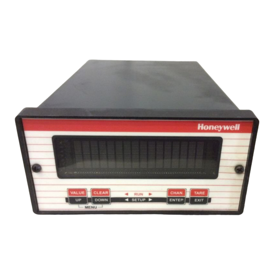
The panel cutout size conforms to the 3/8 DIN standard. Panel-Mounting Jacks (order code AA928) are available that slide into two slots at the sides of the instru- ment. Use the following procedure to mount an SC1000 or SC2000 into a panel. 0123456789ABCDEF... -
Page 28: Rack Mounting
Jacks toward the rear side of the panel, drawing the instrument tightly into place. 4.3.5 Rack Mounting A Rack Mounting Kit (order code AA934) is available for mounting a single SC1000 or SC2000 into a 19”, 2U rack. It includes the Panel-Mounting Jacks described above as well as the 19” rack panel. -
Page 29: Internal Arrangement
Microprocessor Board Up to 4 Input or Output Board Channel boards (1 shown) Figure 4-3: Internal Arrangement of SC1000 and SC2000 The SensoBus Backplane Board serves as the connection between all Power Supply Board Rear Panel SC Series Instruction Manual... -
Page 30: Cleaning
Do not use liquid or aerosol cleaners. Do not allow any cleaner inside the instrument. 4.3.10 Vehicle Power Model SC1000 and SC2000 instruments are available with a vehicle power option for Option operation with batteries and linear DC power supplies. -
Page 31: Model Sc2001
4.4 Model SC2001 4.4.1 Differences Model SC2001 instruments are SC2000 instruments housed in a portable case. 4.4.2 External Arrangement The external arrangement of the AC powered SC2001 is given below 4.4.3 Front Panel The pinout for the 25-pin System connector is provided later in this chapter. pinouts for the individual channels are located in the chapter for that channel. -
Page 32: Internal Arrangement
Step 2: Pull the front panel assembly out of the case. Step 3: Proceed with Model SC2000 “Case Removal” on page 28. 4.4.5 Internal Arrangement See the Model SC2000 “Internal Arrangement” on page 29. 4.4.6 Cleaning Turn off the instrument and unplug all connectors. Use a soft cloth or tissue and a mild cleaner. -
Page 33: Model Sc3004
4.5 Model SC3004 4.5.1 External Arrangement 0123456789ABCDEFGHIJ 0123456789ABCDEFGHIJ 0123456789ABCDEFGHIJ 0123456789ABCDEFGHIJ 4.5.2 Rear Panel The pinout for the 25-pin System connector is provided later in this chapter. The pinouts for the individual channels are located in the chapter for that channel. 4.5.3 Panel Mounting The panel space necessary conforms to the EIA 19”... -
Page 34: Case Removal
4.5.5 Case Removal Disconnect the power cord and all cables from the instrument before attempt- ing to remove the case. Failure to comply with these instructions could result in death or serious injury. CAUTION Use a #0 Phillips screwdriver on the black screws to avoid damaging them. Failure to comply with these instructions may result in product damage. -
Page 35: System Connector
Communication by RS-232 or RS-485. RS-232 DCE standard designations have been maintained. Digital Function Inputs, such as for resetting tare, peak and latched limits Open-collector digital Limit Outputs for limits 1 through 4 (not available on Model SC1000). Chapter 5 System Connector SC Series Instruction Manual... -
Page 36: System Connector Pinout
5.2 System Connector Pinout Name RS-232 IN RS-232 OUT RS-232 Clear to Send (connected to pin 5) RS-232 Request to Send (connected to pin 4) RS-232 Data Carrier Detect (not connected) FUNC 2 Function Input #2:.Clear Peak/Valley & Limits FUNC 1 Function Input #1: Tare Off for all channels FUNC 0 RS-485 TB... -
Page 37: Function Input Pins
5.3 Function Input Pins 5.3.1 Overview To use a Function Input pin (9, 10, 11 or 21), connect it to the DGND (pin 19) momen- tarily. This can be accomplished by a push button switch, relay contact closure, or PLC output. Usually, the Function Input pins perform the default actions described in the “System Connector Pinout”... -
Page 38: Limit Output Pins
5.4 Limit Output Pins 5.4.1 Overview An open-collector output is a transistor logic output that can be used to control DC loads, drive opto-isolators or relays, or interface directly to logic circuitry. They act very much like switches: low resistance when turned on and high resistance when turned off. - Page 39 SC Series Instruction Manual page 39...
- Page 40 page 40 008-0608-00...
-
Page 41: System Menu
6.1 Overview The System menu allows you to examine and change settings that affect the chassis of the SC instrument. You can view the internal software revision and the instrument’s configuration (i.e. what types of cards are installed in each channel). Detailed instructions on operating the SC instrument in the SETUP Menu mode can be found in “SETUP Menu mode”... -
Page 42: Install Channel Menu Item
6.2.4 This menu item will add an Input, Output or Virtual channel as the next highest chan- INSTALL CHANNEL Menu Item nel number in the system. NOTICE Installing a channel will cause it to use the “default” or “empty” configuration information for that channel. - Page 43 Virtual Channel Installation Use the following procedure to install a Virtual Channel: Procedure After installing a Mathematics Virtual channel, you must re-load the SensoCode program into the channel with a computer running the “SensoCom Instrument Util- ity Software”. See “Mathematics Virtual Channel” on page 143 for more informa- tion.
-
Page 44: Delete Channel Menu Item
After a hardware channel has been deleted, you can safely physically remove it from the chassis. See “Case Removal” on page 28 for SC1000 and SC2000 instruments. See “Case Removal” on page 34 for SC3004 instruments. - Page 45 SC Series Instruction Manual page 45...
- Page 46 page 46 008-0608-00...
-
Page 47: Serial Communications
Ask for manual 008-0610-00, “SC Series Communications Guide” or download it from http://www.honeywell.com/sensotec. 7.2 Wiring The System connector on the instrument’s rear panel is used, among other things, for serial communications. -
Page 48: Communications Protocol
7.3 Communications Protocol 7.3.1 RS-232 vs. RS-485 SC Series instruments are available with either of two communications protocols, RS- 232 or RS-485. Only one of these can be installed at a time at the factory. • RS-232 provides for only one receiver and transmitter per loop, and a loop length of no more than 50 feet. -
Page 49: Serial Com Menu
7.4 Serial Com Menu 7.4.1 Overview The Serial Com menu allows you to examine and change the settings for serial com- munications as well as test the communications link. Detailed instructions on operating the SC instrument in the SETUP Menu mode can be found in “SETUP Menu mode”... - Page 50 page 50 008-0608-00...
-
Page 51: Display Menu
SC instrument. You can change which channel is dis- played when the instrument is powered-up and what information is shown on the lower line of SC1000, SC2000 and SC2001 instruments. Detailed instructions on operating the SC instrument in the SETUP Menu mode can be found in “SETUP Menu mode”... - Page 52 page 52 008-0608-00...
-
Page 53: Chapter 9 Limits
Chapter 9 Limits 9.1 Understanding Limits, Set Points and Return Points Limits are signal levels at which some action (such as a light to come on or go out, or a switch to close) is desired to take place. The point at which this action takes place is the SET POINT. -
Page 54: Limit Operation
9.2 Limit Operation 9.2.1 Actions When When Limits 1, 2, 3, or 4 are activated, the following actions occur: Activated • The front panel light for the limit will illuminate. • The corresponding open-collector Limit Output pin on the System connector will be connected to the DGND (Digital Ground) pin. -
Page 55: Limit Menus
9.3 Limit Menus 9.3.1 Overview There are four, eight, twelve or sixteen Limit menus depending on how many Relay Output channels are installed in the instrument. These menus determine the operation of the each of the limits. If no Relay Output channels are installed, there are four Limit menus which control the operation of the open-collector Limit Outputs on the System connector. - Page 56 page 56 008-0608-00 Figure 9-1: Limit Operation when LIMIT.ENERGIZE Figure 9-2: Limit Operation when LIMIT.ENERGIZE Figure 9-3: Limit Operation when LIMIT.ENERGIZE SIGNAL > SETPOINT SIGNAL < SETPOINT SIGNAL INSIDE...
-
Page 57: Limit.latching Menu Item
9.3.6 This specifies whether to latch the activated limit so that only manually clearing the LIMIT.LATCHING Menu Item limit will deactivate it. [CLEAR] button, sending the “F8” serial communications command, or by using the Function Input #2 (Clear Peak/Valley & Limits pin on the System Connector. See “Function Input Pins”... - Page 58 page 58 008-0608-00...
-
Page 59: Strain-Gage Input Channel
10.1 Features The Strain-Gage Input channel provides a DC excitation voltage to and accepts millivolt signals from strain-gage transducers. These millivolt signals are digitized, converted into engineering units, and placed into the track, peak and valley data values of the channel. Setup and calibration of the channel can be made manu- ally through the SETUP mode or automatically if the transducers are equipped with Signature Calibration. -
Page 60: Wiring
10.2 Wiring Connect the transducer to a Strain-Gage Input channel by wiring it to the 12-pin con- nector of that channel. The Customer Information Sheet that shipped with the instru- ment describes which cards are installed in each channel. The pin-out for this connector is shown on the following table. -
Page 61: Calibration Procedure
10.3 Calibration Procedure If you are not familiar with operating the instrument in the SETUP menu mode, see “SETUP Menu mode” on page 23. A listing of all menu items is given in “Setup Menu Reference” on page 157. Step 1: Wire the transducer to the channel’s connector. Step 2: Enter the Step 3: Enter the Step 4: Perform the calibration. -
Page 62: Specifications
10.4 Specifications Resolution and Frequency Response INSTRUMENT-ONLY ACCURACY (Sense wires used;Frequency Response setting<=16Hz; Output current range (optional current page 62 008-0608-00 TRANSDUCER INPUT Transducer type Excitation Voltage short circuit protected with sensing Transducer full-scale output .5 to 11.0 mV/V @ 5V excitation .5 to 5.5 mV/V @ 10 V excitation Amplifier Gain Selection Calibration Type... -
Page 63: Channel Menu
10.5 Channel Menu Each Strain-Gage Input channel is configured and calibrated via its channel menu. Detailed instructions on operating the instrument in the SETUP Menu mode can be found in “SETUP Menu mode” on page 23. A diagram of all menus is located in “Setup Menu Reference”... - Page 64 Menu Item This menu selects which value is displayed by the channel when first entering the POWER-ON SOURCE RUN mode. The choices are: • “ TRACK • “ PEAK • “ VALLEY • “ TRACK / PEAK (Only available on Model SC3004). •...
-
Page 65: Display Setup Sub-Menu
10.5.2 This menu controls how data values are displayed by the channel and transmitted DISPLAY SETUP Sub-Menu via serial communications. Menu Item Selects the number of digits displayed by the channel. The choices are: DISPLAY. DIGITS • • • This menu item may be automatically updated by a transducer’s Signature Mod- ule. -
Page 66: Auxn Function Menu Items
10.5.3 AUXn FUNCTION AUX1 FUNCTION Menu Items Auxiliary Function pins (labeled as “AUX1” and “AUX2”) on the channel’s connector are activated. These pins are “activated” when they are connected to the (-)Signature (labeled as “-MEM”) pin. The choices are: • “... -
Page 67: Calibration Type Menu Item
10.5.4 This chooses the type of calibration technique to be used. There are three meth- CALIBRATION TYPE Menu Item ods that can be used to calibrate the transducer to the Input Channel. Each has advantages and disadvantages as described in the table below..when frequently swapping ...when best possible accuracy Requires actual, calibrated loads... - Page 68 a known, precision resistor into the transducer circuit, which causes a predictable apparent signal. The instrument then takes a reading and adjusts itself using the “ SHUNT CAL VALUE • “ TYPE= MV/V CAL apply the load entered in the “ a reading from an accurate, internal mV/V reference.
-
Page 69: Calibration Data Sub-Menu
10.5.5 This enters the values that will be used by the instrument when it calibrates itself CALIBRATION DATA Sub-Menu to the transducer. The menu items that are displayed will change according to what the Menu Item This sets the excitation voltage used to power up the transducer. The choice are: EXCITATION •... - Page 70 To verify proper transducer operation, you can apply the shunt resistor to the trans- ducer while the instrument is in the RUN mode. Press and hold the [ENTER] button for three seconds; this will apply the shunt resistor and display the reading. Menu Items This enters the engineering units for the known-load calibration points.
-
Page 71: Calibrate Menu Item
10.5.6 Menu This menu item performs a calibration according to what was entered in the CALIBRATE Item BRATION TYPE NOTICE Before performing a calibration, the transducer must be connected to the instrument, the Menu Item” on page 67), and the BRATION DATA Sub-Menu”... - Page 72 applied this load to the transducer, press [ENTER]. • Upon completion, the display will indicate RUN mode. If the CALIBRATION TYPE • The display will read 00000 and UNIT are previously entered as When you have applied this load to the transducer, press [ENTER]. •...
-
Page 73: Dac Setup Sub-Menu
10.5.7 Sub-Menu This sub-menu contains four items that control the Digital-to-Analog Converter DAC SETUP (DAC) output of the channel. Menu Item This chooses which channel will drive the DAC output. Normally, the DAC located DAC. CHANNEL on a particular channel will be driven by that channel, but that need not be the case. -
Page 74: Signature Module Sub-Menu
10.5.8 SIGNATURE Sub-Menu MODULE Menu Item Updates the information stored in the transducer’s Signature Module with any new UPDATE SIG.MOD? settings that is entered into the instrument with the SETUP menus. The settings that will be updated are: • EXCITATION •... -
Page 75: Diagnostics Sub-Menu
10.5.9 DIAGNOSTICS Sub-Menu Menu Item When this menu item is selected, the Analog Output of the channel is forced to its DAC FULL SCALE full-scale output, then trimming the readout connected to the Analog Output. Menu Item When this menu item is selected, the Analog Output of the channel is forced to its DAC ZERO SCALE zero-scale output, then trimming the readout connected to the Analog Output. -
Page 76: Analog Output Configuration
10.6 Analog Output Configuration 10.6.1 Identifying the A Strain-Gage Input channel is available with one of two types of digital-to-analog Output Type (DAC) outputs: voltage or current. You can determine which type of output a channel has by one of three ways: •... -
Page 77: Troubleshooting
10.7 Troubleshooting 10.7.1 Error Messages See “Error Messages” on page 151 for information relating to error messages. 10.7.2 Common Problems and Solutions Erratic Display Check electrical connections for continuity and the transducer’s wiring code from its Certificate of Calibration. Make sure that the load on the transducer is constant. Check millivolt input to the (+)Signal (“+SIG”) and (-)Signal (“-SIG”) pins with a voltmeter. - Page 78 See “Unamplified Transducer Connection to Strain-Gage Input Channel” on page 60, “External Arrangement of AC powered SC1000 and SC2000” on page 27 and “External Arrangement of Model SC3004” on page 33.
-
Page 79: Chapter 11 Ac/Ac-Lvdt Input Channel
11.1 Features The AC/AC-LVDT Input channel provides an AC excitation voltage to and accepts AC signals from LVDT (Linear Variable Differential Transformer) transducers. These signals are digitized, converted into engineering units, and placed into the track, peak and valley data values of the channel. Setup and calibration of the channel are made manually through the SETUP mode. -
Page 80: Wiring
11.2 Wiring Connect your transducer to an AC/AC-LVDT Input channel by wiring it to the 12-pin connector of that channel. The Customer Information Sheet that shipped with the instrument describes which cards are installed in each channel. The pin-out for this connector is shown on the following table. -
Page 81: Calibration Procedure
11.3 Calibration Procedure If you are not familiar with operating the instrument in the SETUP menu mode, see “SETUP Menu mode” on page 23. A listing of all menu items is given in “Setup Menu Reference” on page 157. Step 1: Wire the transducer to the channel’s connector. Step 2: Enter the Step 3: Enter the Step 4: Determine the LVDT’s electrical null point, then physically mount it. -
Page 82: Specifications
11.4 Specifications Voltage range (voltage output Current range (current output page 82 008-0608-00 TRANSDUCER INPUT Transducer type Excitation Voltage Transducer full-scale output .1 to 15 VRMS @ 3 VRMS excitation Amplifier Gain Selection Calibration Type 2-, 3- or 5- point known displacement A/D Converter Low-pass filter Resolution... -
Page 83: Channel Menu
11.5 Channel Menu Each AC/AC-LVDT Input channel is configured and calibrated via its channel menu. Detailed instructions on operating the instrument in the SETUP Menu mode can be found in “SETUP Menu mode” on page 23. A diagram of all menus is located in “Setup Menu Reference”... - Page 84 Menu Item This menu selects which value is displayed by the channel when first entering the POWER-ON SOURCE RUN mode. The choices are: • “ TRACK • “ PEAK • “ VALLEY • “ TRACK / PEAK (Only available on Model SC3004). •...
-
Page 85: Display Setup Sub-Menu
11.5.2 This menu controls how data values are displayed by the channel and transmitted DISPLAY SETUP Sub-Menu via serial communications. Menu Item Selects the number of digits displayed by the channel. The choices are: DISPLAY. DIGITS • • • Menu Item Selects the decimal point location on the channel’s display and serial communica- DISPLAY. - Page 86 updated. • “ HIGH/LOW HOLD • “ HIGH/LOW CLEAR • “ TARE ON • “ TARE OFF As the Auxiliary Function pins are not isolated, it is recommended that a push-button switch or relay is used to connect these pins to the DGND pin. page 86 008-0608-00 ”...
-
Page 87: Calibration Type Menu Item
11.5.4 The choices for this menu item are: CALIBRATION TYPE Menu Item • • • The selection of the calibration type affects what menu items appear in the BRATION DATA “ ” means 2-Point Known Displacement Calibration. You are TYPE= 2 POINT CAL prompted to apply the displacements to the transducer that were entered in the “... -
Page 88: Calibration Data Sub-Menu
11.5.5 This sub-menu enters the values that will be used by the instrument when it calibrates CALIBRATION Sub-Menu itself to the transducer. The menu items that are displayed will change according to DATA what the Menu Item The transducer output when its full-scale displacement is applied to it, in Volts RMS FULL SCALE VRMS (root-mean-squared) assuming 3 VRMS excitation. -
Page 89: Calibrate Menu Item
11.5.6 Menu This menu item performs a calibration according to what was entered in the CALIBRATE Item BRATION TYPE NOTICE Before performing a calibration, the transducer must be connected to the instrument, the be selected (see “CALIBRATION TYPE Menu Item” on page 87) and the TION DATA NOTICE For maximum accuracy, allow at least twenty minutes of warm-up with the exci-... - Page 90 previously entered as this displacement to the transducer, press [ENTER]. • The display will read viously entered as displacement to the transducer, press [ENTER]. • The display will read viously entered as displacement to the transducer, press [ENTER]. • Upon completion, the display will indicate RUN mode.
-
Page 91: Dac Setup Sub-Menu
11.5.7 Sub-Menu This sub-menu contains four items that control the Digital-to-Analog (DAC) output DAC SETUP of the channel. Menu Item This chooses which channel will drive the DAC output. Normally, the DAC located DAC. CHANNEL on a particular channel will be driven by that channel, but that need not be the case. -
Page 92: Diagnostics Sub-Menu
11.5.8 DIAGNOSTICS Sub-Menu Menu Item When this menu item is selected, the Analog Output of the channel is forced to its full- DAC FULL SCALE scale output, then the readout connected to the Analog Output. Menu Item When this menu item is selected, the Analog Output of the channel is forced to its DAC ZERO SCALE zero-scale output, then ming the readout connected to the Analog Output. -
Page 93: Electrical Null And Transducer Mounting
11.6 Electrical Null and Transducer Mounting 11.6.1 Overview The mechanical travel of an LVDT transducer is not the same as its usable mea- suring range. All LVDTs exhibit some non-linearity near the ends of its armature’s mechanical travel. To insure that the LVDT will be used in its linear measuring range, its electrical null point must be determined. -
Page 94: Analog Output Configuration
11.7 Analog Output Configuration 11.7.1 Identifying the An AC/AC-LVDT Input channel is available with one of two types of digital-to-analog Output Type (DAC) outputs: voltage or current. You can determine which type of output a channel has by one of three ways: •... -
Page 95: Troubleshooting
See “Connection of Four- or Five-wire AC/AC-LVDT” on page 80, “External Arrangement of AC powered SC1000 and SC2000” on page 27 and “External Arrangement of Model SC3004” on page 33. - Page 96 page 96 008-0608-00...
-
Page 97: High-Level Input Channel
Chapter 12 High-Level Input Channel 12.1 Features The High-Level Input channel provides a DC supply voltage to and accepts volt- age or current signals from amplified transducers such as pressure transducers, load cells and DC-DC LVDTs. These signals are digitized, converted into engi- neering units, and placed into the track, peak and valley data values of the chan- nel. -
Page 98: Wiring
12.2 Wiring 12.2.1 Channel Connect the amplified transducer, in-line amplifier or DC-DC LVDT to a High-Level Connector Input channel by wiring it to the 12-pin connector of that channel. The Customer Infor- mation Sheet that shipped with the instrument describes which cards are installed in each channel. -
Page 99: Bi-Polar Voltage Amplifiers
12.2.2 Bi-polar Voltage Use the following wiring diagram when connecting an amplified transducer, in-line Amplifiers amplifier or DC-DC LVDT with a bi-polar voltage amplifier to a High-Level Input channel. Examples of such devices include • • • NOTICE See “Low Voltage DC-DC LVDTs” on page 105 for information on wiring Model DLB, DLE and DLF low-voltage DC-DC LVDTs. -
Page 100: 3-Wire Voltage" Amplifiers
12.2.3 “3-wire Use the following wiring diagram when connecting an amplified transducer or in-line Voltage” Amplifiers amplifier with a 3-wire voltage amplifier to a High-Level Input channel. Examples of such devices include • transducers with Option 2c or Option 2t internal amplifiers (with shunt cal) •... -
Page 101: 3-Wire Voltage" Amplifiers With Single-Wire Shunt Cal
12.2.4 “3-wire Voltage” Use the following wiring diagram when connecting an amplified transducer with a Amplifiers with Single-wire 3-wire voltage amplifier with single-wire shunt calibration to a High-Level Input channel. An example of a such device includes Shunt Cal • The High-Level Input channel’s Configuration Jumpers must be set as follows for proper operation. -
Page 102: 3-Wire Current" Amplifiers
12.2.5 “3-wire Current” Use the following wiring diagram when connecting an amplified transducer or in-line Amplifiers amplifier with a 3-wire current amplifier to a High-Level Input channel. Examples of such devices include • transducers with the Option 2j internal amplifier (with shunt cal) •... -
Page 103: 2-Wire Current" Amplifiers With Buffered Shunt Cal
12.2.6 “2-wire Current” Use the following wiring diagram when connecting an amplified transducer or in- Amplifiers with Buffered line amplifier with a 2-wire current amplifier to a High-Level Input channel. Exam- ples of such devices include Shunt Cal • • •... -
Page 104: 2-Wire Current" Amplifiers With Single-Wire Shunt Cal
12.2.7 “2-wire Current” Use the following wiring diagram when connecting an amplified transducer or in-line Amplifiers with Single- amplifier with a 2-wire current amplifier to a High-Level Input channel. Examples of such devices include wire Shunt Cal • transducers with the Option 2p internal amplifier (not equipped with shunt cal) •... -
Page 105: Low Voltage Dc-Dc Lvdts
12.2.8 Low Voltage DC-DC Use the following wiring diagram when connecting a low-voltage DC-DC LVDT to LVDTs a High-Level Input channel. Examples of such devices include • The High-Level Input channel’s Configuration Jumpers must be set as follows for proper operation. See “Excitation and Signal Jumpers” on page 106. •... -
Page 106: Excitation And Signal Jumpers
12.3 Excitation and Signal Jumpers 12.3.1 Overview The High-Level Input channel has hardware jumpers which allows configuration of excitation supply voltages and signal inputs to match the wide variety of amplified pressure, load and DC-DC LVDT transducers. CAUTION “Wiring” on page 98 explains which jumpers settings are required for a particu- lar transducer type. -
Page 107: Calibration Procedure
12.4 Calibration Procedure If you are not familiar with operating the instrument in the SETUP menu mode, see “SETUP Menu mode” on page 23. A listing of all menu items is given in “Setup Menu Reference” on page 157. Step 1: Wire the transducer to the channel’s connector. Step 2: Set the Excitation and Signal jumpers appropriate for the transducer, Step 3: Enter the Step 4: Enter the... -
Page 108: Specifications
Resolution and Frequency Response INSTRUMENT-ONLY ACCURACY (Frequency Response setting<=16Hz; Linearity, repeat- Output current range (optional current Total excitation current of all channels must not exceed 120mA for Models SC1000, SC2000 or SC2001 and 310 mA for Model SC3004. page 108 008-0608-00... -
Page 109: Channel Menu
12.6 Channel Menu Each High-Level Input channel is configured and calibrated via its channel menu. Detailed instructions on operating the instrument in the SETUP Menu mode can be found in “SETUP Menu mode” on page 23. A diagram of all menus is located in “Setup Menu Reference”... - Page 110 • “ PEAK • “ VALLEY • “ TRACK / PEAK (Only available on Model SC3004). • “ TRACK / VALLEY (Only available on Model SC3004). • “ PEAK / VALLEY (Only available on Model SC3004). page 110 008-0608-00 ” means the highest value of the channel. ”...
-
Page 111: Display Setup Sub-Menu
12.6.2 This menu controls how data values are displayed by the channel and transmitted DISPLAY SETUP Sub-Menu via serial communications. Menu Item Selects the number of digits displayed by the channel. The choices are: DISPLAY. DIGITS • • • Menu Item Selects the decimal point location on the channel’s display and serial communica- DISPLAY. -
Page 112: Auxn Function Menu Items
12.6.3 AUXn FUNCTION AUX1 FUNCTION Menu Items Auxiliary Function pins (labeled as “AUX1” and “AUX2”) on the channel’s connector are activated. These pins are “activated” when connected to the DGND pin. The choices are: • “ DISABLED • “ TRACK HOLD •... -
Page 113: Calibration Type Menu Item
12.6.4 This chooses the type of calibration technique to be used. There are two methods CALIBRATION TYPE Menu Item that can be used to calibrate the transducer to the Input Channel. Each has advantages and disadvantages as described in the table below..when frequently swapping ...when best possible accuracy Requires actual, calibrated loads... - Page 114 used to compensate for the non-linearity in the transducer. The usual loads used are zero scale, half scale and full scale, but you are not restricted to these loads. • “ to apply the loads to the transducer that were entered in the “ “...
-
Page 115: Calibration Data Sub-Menu
12.6.5 This enters the values that will be used by the instrument when it calibrates itself CALIBRATION DATA Sub-Menu to the transducer. The menu items that are displayed will change according to what the The nominal transducer/amplifier output when its full-scale load is applied to it, in FULL SCALE VOLT Menu Item volts or milliamps. - Page 116 ity. • “ ity. • “ capacity. When using the 5-Point Known Load Calibration type, the following menu items are available: • “ ity. • “ ity. • “ ity. • “ ity. • “ capacity. NOTICE To insure both correct operation of the transducer and application of the load, the instrument expects the voltage or current applied at each known-load point to be increasing.
-
Page 117: Calibrate Menu Item
12.6.6 Menu This menu item performs a calibration according to what was entered in the CALIBRATE Item BRATION TYPE NOTICE Before performing a calibration, • • • • NOTICE For maximum accuracy, allow at least twenty minutes of warm-up with the exci- tation voltage applied to the transducer before calibration. - Page 118 If the • The display will read (where 00000 and UNIT are previously entered as UNITS • The display will read previously entered as applied this load to the transducer, press [ENTER]. • The display will read previously entered as applied this load to the transducer, press [ENTER].
-
Page 119: Dac Setup Sub-Menu
12.6.7 Sub-Menu This sub-menu contains four items that control the Digital-to-Analog Converter DAC SETUP (DAC) output of the channel. Menu Item This chooses which channel will drive the DAC output. Normally, the DAC located DAC. CHANNEL on a particular channel will be driven by that channel, but that need not be the case. -
Page 120: Diagnostics Sub-Menu
12.6.8 DIAGNOSTICS Sub-Menu Menu Item When this menu item is selected, the Analog Output of the channel is forced to its DAC FULL SCALE full-scale output, then trimming the readout connected to the Analog Output. Menu Item When this menu item is selected, the Analog Output of the channel is forced to its DAC ZERO SCALE zero-scale output, then trimming the readout connected to the Analog Output. -
Page 121: Analog Output Configuration
12.7 Analog Output Configuration 12.7.1 Identifying the A High-Level Input channel is available with one of two types of digital-to-analog Output Type (DAC) outputs: voltage or current. You can determine which type of output a channel has by one of three ways: •... -
Page 122: Troubleshooting
“cable shield connection screw” on the rear panel of the instrument. See “Wiring” on page 98, “External Arrangement of AC powered SC1000 and SC2000” on page 27 and “External Arrangement of Model SC3004” on page 33. -
Page 123: Relay Output Channel
13.1 Features 13.1.1 First Channel The first Relay Output channel installed in an instrument supplements the stan- Installed dard four limits (Limit 1, Limit 2, Limit 3 and Limit 4) . Its four, dry contact relay out- puts will mirror the Limit Outputs pins of the System connector. In the 01-04 13.1.2 Second Channel... -
Page 124: Wiring
13.2 Wiring The pin-out for the Relay Output channel’s 12-pin connector is shown in the following table. 1 (top) 12 (bottom) page 124 008-0608-00 Table 2-8: Relay Output Channel Pin Connections Label RELAY1 NC Relay 1 normally closed RELAY1 C Relay 1 common RELAY1 NO Relay 1 normally open... -
Page 125: Setup Procedure
13.3 Setup Procedure If you are not familiar with operating the instrument in the SETUP menu mode, see “SETUP Menu mode” on page 23. A listing of all menu item is given in “Setup Menu Reference” on page 157. Step 1: Wire to the channel’s connector. Step 2: Use the appropriate Limit Menu to setup the limits. -
Page 126: Specifications
13.4 Specifications RELAY OUTPUT Quantity and Type 4 form C Contact Rating 0.5A @ 50VAC max. (consult factory for 125VAC max. operation) 1A @ 30VDC max. page 126 008-0608-00... -
Page 127: Channel Menu
13.5 Channel Menu The Relay Output channel’s SETUP menu allows you to manually turn the relays on and off to verify that they are functioning. To change the operation of the limits, see “Limit Menus” on page 55. Detailed instructions on operating the instrument in the SETUP Menu mode can be found in “SETUP Menu mode”... - Page 128 page 128 008-0608-00...
-
Page 129: Dac Output Channel
Chapter 14 DAC Output Channel 14.1 Features The DAC Output channel uses a digital-to-analog converter to generate a voltage or current from any channel’s track, peak or valley value. This type of channel is often used to provide a Mathematics Virtual channel with an analog output. SC Series Instruction Manual page 129... -
Page 130: Wiring
14.2 Wiring Connect your readout instrument to a DAC Output channel by wiring it to the 12-pin connector of that channel. The Customer Information Sheet that shipped with the instrument describes which cards are installed in each channel. The pin-out for this connector is shown on the following table. -
Page 131: Setup Procedure
14.3 Setup Procedure If you are not familiar with operating the instrument in the SETUP menu mode, see “SETUP Menu mode” on page 23. A listing of all menu items is given in “Setup Menu Reference” on page 157. Step 1: Determine if you have a Voltage DAC Output channel or a Current DAC Step 2: Wire the readout instrument to the channel’s connector. -
Page 132: Specifications
14.4 Specifications ANALOG OUTPUT Voltage range (voltage output 5, ±5 or 10 VDC channels) Current range (current output 4-20 mA channels) Source any channel’s track, peak or valley value Isolation 500V Resolution 12 bits Update Rate depends on how many channels are installed in the instrument page 132 008-0608-00... -
Page 133: Channel Menu
14.5 Channel Menu Each DAC Output channel is configured and calibrated via its channel menu. Detailed instructions on operating the instrument in the SETUP Menu mode can be found in “SETUP Menu mode” on page 23. A diagram of all menus is located in “Setup Menu Reference”... -
Page 134: Diagnostics Sub-Menu
14.5.2 DIAGNOSTICS Sub-Menu Menu Item When this menu item is selected, the Analog Output of the channel is forced to its full- DAC FULL SCALE scale output, then the readout connected to the Analog Output. Menu Item When this menu item is selected, the Analog Output of the channel is forced to its DAC ZERO SCALE zero-scale output, then ming the readout connected to the Analog Output. -
Page 135: Analog Output Configuration
14.6 Analog Output Configuration 14.6.1 Identifying the A DAC Output channel is available with one of two types of digital-to-analog Output Type (DAC) outputs: voltage or current. You can determine which type of output a channel has by one of three ways: •... -
Page 136: Troubleshooting
14.7 Troubleshooting 14.7.1 Error Messages See “Error Messages” on page 151 for information relating to error messages. 14.7.2 Common Problems and Solutions Analog Output Incorrect Make certain of the type of Analog Output (voltage or current) that the channel is equipped with;... - Page 137 SC Series Instruction Manual page 137...
- Page 138 page 138 008-0608-00...
-
Page 139: Split Display Virtual Channel
Split Displays are most useful on chassis with a 16-character display such as the Models SC1000, SC2000 and SC2001. The quad-line, 20-character display of the Model SC3004, however, already allows an Input Channel to show its own Track &... -
Page 140: Channel Menu
15.4 Channel Menu Detailed instructions on operating the instrument in the SETUP Menu mode can be found in “SETUP Menu mode” on page 23. A diagram of all menus is located in “Setup Menu Reference” on page 157. Menu Item This specifies the channel that is displayed on the left half of the split display. - Page 141 SC Series Instruction Manual page 141...
- Page 142 page 142 008-0608-00...
-
Page 143: Mathematics Virtual Channel
16.1 Features The Mathematics Virtual Channel is a powerful, flexible means to allow SC Series Instruments to perform simple to moderate functions that previously required the use of expensive programmable logic controllers (PLC). A Mathematics Virtual Channel is akin to a PLC; it can execute programs written in an interpretive language called SensoCode. -
Page 144: Wiring
16.2 Wiring A Virtual Channel exists in software only; it does not occupy a physical slot inside of the instrument’s chassis. However, a Virtual Channel does require a channel number. A SensoCode program that is executed by a Mathematics Virtual Channel can use the System connector’s Limit Output pins and Function Input pins for its own purposes. -
Page 145: Setup Procedure
16.3 Setup Procedure If you are not familiar with operating the instrument in the SETUP menu mode, see “SETUP Menu mode” on page 23. A listing of all menu item is given in “Setup Menu Reference” on page 157. Step 1: Examine the Supplemental Instructions. Step 2: Wire to the pins on the System connector. -
Page 146: Channel Menu
16.4 Channel Menu Each Mathematics Virtual Channel can have its configuration and SensoCode pro- gramming examined via its channel menu. It is not possible to alter the SensoCode program with the SETUP menu. Detailed instructions on operating the instrument in the SETUP Menu mode can be found in “SETUP Menu mode”... -
Page 147: Display Setup Sub-Menu
16.4.5 This menu controls how data values are displayed by the channel and transmitted DISPLAY SETUP Sub-Menu via serial communications. Menu Item Selects the number of digits displayed by the channel. The choices are: DISPLAY. DIGITS • • • Menu Item Selects the decimal point location on the channel’s display and serial communica- DISPLAY. -
Page 148: Power-On Source Menu Item
16.4.6 This menu selects which value is displayed by the channel when first entering the POWER-ON SOURCE Menu Item RUN mode. For single-line displays, the choices are: • “ TRACK • “ PEAK • “ VALLEY For multi-line displays, the choices are: •... -
Page 149: Troubleshooting
16.5 Troubleshooting See “Error Messages” on page 151 for information relating to error messages. NOTICE Supplemental Instructions included with the instrument may contain important information about which indicator lights, Function Input pins and/or Limit Output pins of the System connector are used by the Mathematics Virtual channel. SC Series Instruction Manual page 149... - Page 150 page 150 008-0608-00...
-
Page 151: Error Messages
17.1 Overview If the instrument detects an error during the RUN, INITIALIZE, or SETUP modes, it stops operation and enters its ERROR mode as described in “Operating Modes” on page 19. The most frequent causes of error messages are: • •... -
Page 152: Error Message List
17.2 Error Message List Error 05, A Mathematics Virtual channel has attempted to divide by zero. DIVIDE BY ZERO Error 07, A Mathematics Virtual channel has attempted to take the square root of a negative SQUARE ROOT number. Error 09, A Mathematics Virtual channel has attempted to take the logarithm of either zero or a LOG/LN negative number. - Page 153 Error 29, A verification failure occurred during a write operation to the channel’s EEPROM. S.EE VERIFY FAIL Restart the instrument. Error 30, The channel’s EEPROM could not be detected during an erase operation. Check S.EE ERASE NAK that the channel’s address jumpers are set properly. Error 31, The channel does not appear to have been installed properly.
- Page 154 SEN”) are not connected to the (+)Excitation and (-)Excitation pins (labeled as “+EXC” and “-EXC”), respectively, unplugged from the channel. If you are not interested in the using this channel and you wish to suppress this error, see “DISABLE CHANNEL Menu Item” on page 75. Error 47, When installing a channel, the EEPROM type requested by the channel is not valid.
- Page 155 Error 61, A load applied during a known-load calibration was not greater than a previously LOAD NOT GT LOAD applied load. To insure both correct operation of the transducer and application of the load, the instrument expects the voltage applied at each known-load point to be increasing.
- Page 156 Error 85, The destination step of a “Go to” Instruction is beyond the end of the SensoCode pro- UNREACHABLE GOTO gram. The SensoCode program loaded in the Mathematics Virtual channel is invalid. Error 87, The SensoCode program contains a “Go to” Instruction that has not been converted GOTO NOT JUMP into a “Jump”...
-
Page 157: Setup Menu Reference
18.1 Navigation instructions • • • • • Press [UP]+[DOWN] to enter the SETUP menu mode. Press [UP] to move up. Press [DOWN] to move down. Press [ENTER] to select an item. Press [EXIT] to re-start the instrument. SC Series Instruction Manual Chapter 18 Setup Menu Reference page 157... - Page 158 CHANNEL 01 MENU CHANNEL 02 MENU CHANNEL 03 MENU CHANNEL 04 MENU CHANNEL 05 MENU CHANNEL 06 MENU CHANNEL 07 MENU CHANNEL 08 MENU CHANNEL 09 MENU CHANNEL 10 MENU CHANNEL 11 MENU CHANNEL 12 MENU CHANNEL 13 MENU CHANNEL 14 MENU CHANNEL 15 MENU CHANNEL 16 MENU CHANNEL 17 MENU...
- Page 159 SYSTEM MENU SOFTWARE REVISION CONFIGURATION DIAGNOSTICS INSTALL CHANNEL DELETE CHANNEL DEFAULT CHANNEL LEAVE MENU Table 7-11: System Menu DISPLAY TYPE CHANNEL 01 TYPE CHANNEL 02 TYPE CHANNEL 03 TYPE CHANNEL 04 TYPE CHANNEL 05 TYPE CHANNEL 06 TYPE CHANNEL 07 TYPE CHANNEL 08 TYPE CHANNEL 09 TYPE CHANNEL 10 TYPE...
- Page 160 LIMIT xx MENU SERIAL COM MENU DISPLAY MENU DISPLAY MENU page 160 008-0608-00 Table 7-12: LIMIT MENU LIMIT. ENABLE LIMIT. SETPOINT LIMIT. RETURN PNT LIMIT. ENERGIZE SIGNAL>SETPOINT SIGNAL<SETPOINT SIGNAL INSIDE SIGNAL OUTSIDE LIMIT. LATCHING LIMIT. CHANNEL LIMIT. SOURCE TRACK PEAK VALLEY LEAVE MENU Table 7-13: SERIAL COMMUNICATIONS Menu...
- Page 161 Table 7-16: Strain Gage Input Channel Menu CHANNEL xx MENU OPERATION DISPLAY SETUP AUX1 FUNCTION AUX2 FUNCTION CALIBRATION TYPE AUTO-ZERO FREQ. RESPONSE 002. HERTZ/FAST 002. HERTZ 008. HERTZ 016. HERTZ 032. HERTZ 050. HERTZ 100. HERTZ 250. HERTZ 500. HERTZ 800.
- Page 162 CALIBRATION DATA CALIBRATE DAC SETUP SIGNATURE MODULE DIAGNOSTICS LEAVE MENU page 162 008-0608-00 Table 7-16: Strain Gage Input Channel Menu (Continued) TYPE=2 POINT CAL TYPE=3 POINT CAL TYPE=5 POINT CAL EXCITATION FULL-SCALE MV/V FULL-SCALE VALUE ZERO-SCALE VALUE SHUNT CAL VALUE KNOWN LOAD POINT 1/5 KNOWN LOAD POINT 2/5 KNOWN LOAD POINT 3/5...
- Page 163 Table 7-17: AC-AC LVDT Input Channel Menu CHANNEL xx MENU OPERATION DISPLAY SETUP AUX1 FUNCTION AUX2 FUNCTION CALIBRATION TYPE AUTO-ZERO FREQ. RESPONSE 002. HERTZ/FAST 002. HERTZ 008. HERTZ 016. HERTZ 032. HERTZ 050. HERTZ 100. HERTZ 250. HERTZ 500. HERTZ 800.
- Page 164 CALIBRATION DATA CALIBRATE DAC SETUP DIAGNOSTICS LEAVE MENU page 164 008-0608-00 Table 7-17: AC-AC LVDT Input Channel Menu (Continued) TYPE=5 POINT CAL FULL SCALE VRMS KNOWN LOAD POINT 1/5 KNOWN LOAD POINT 2/5 KNOWN LOAD POINT 3/5 KNOWN LOAD POINT 4/5 KNOWN LOAD POINT 5/5 LEAVE SUB-MENU DAC.
- Page 165 Table 7-18: High-Level Input Channel Menu CHANNEL xx MENU OPERATION DISPLAY SETUP AUX1 FUNCTION AUX2 FUNCTION CALIBRATION TYPE AUTO-ZERO FREQ. RESPONSE 002. HERTZ/FAST 002. HERTZ 008. HERTZ 016. HERTZ 032. HERTZ 050. HERTZ 100. HERTZ 250. HERTZ 500. HERTZ 800. HERTZ POWER-ON SOURCE TRACK PEAK...
- Page 166 CALIBRATION DATA CALIBRATE DAC SETUP DIAGNOSTICS LEAVE MENU page 166 008-0608-00 Table 7-18: High-Level Input Channel Menu (Continued) TYPE=3 POINT CAL TYPE=5 POINT CAL FULL-SCALE VOLT/CURR FULL-SCALE VALUE ZERO-SCALE VALUE SHUNT CAL VALUE KNOWN LOAD POINT 1/5 KNOWN LOAD POINT 2/5 KNOWN LOAD POINT 3/5 KNOWN LOAD POINT 4/5 KNOWN LOAD POINT 5/5...
- Page 167 Table 7-19: Relay Output Channel CHANNEL xx MENU DIAGNOSTICS LEAVE MENU Table 7-20: DAC Output Channel Menu CHANNEL xx MENU DAC SETUP DIAGNOSTICS LEAVE MENU Table 7-21: Split Display Virtual Channel CHANNEL xx MENU LEFT CHANNEL LEFT SOURCE RIGHT CHANNEL RIGHT SOURCE LEAVE MENU RELAY 1...
- Page 168 CHANNEL xx MENU SENSOCODE P/N USER VALUES VIEW SENSOCODE VIEW COMMANDS DISPLAY SETUP POWER-ON SOURCE LEAVE MENU page 168 008-0608-00 Table 7-22: Mathematics Virtual Channel (item name may vary) page 146 USER VALUE 1 (item name may vary) USER VALUE 2 (item name may vary) USER VALUE 3 (item name may vary)
-
Page 169: Index
VALUE 20 calibration AC/AC-LVDT Input channel 81 High-Level Input channel 107 Strain-Gage Input channel 61 case removal of SC1000 and SC2000 28 of SC2001 31 of SC3004 34 channel address jumpers 42 changing which is displayed 21, 51 clearing peak and valley 20... - Page 170 AC/AC-LVDT Input channel 83 High-Level Input channel 109 Strain-Gage Input channel 63 fuse replacement of SC1000 and SC2000 30 of SC2001 32 of SC3004 34 High-Level Input channel 97 2-Point Known Load Calibration 113, 115, 117 3-Point Known Load Calibration 113, 115, 117 5-Point Known Load Calibration 113–114, 116, 118...
- Page 171 OVLD AC/AC-LVDT Input channel 95 High-Level Input channel 122 Strain-Gage Input channel 77 panel mounting of SC1000 and SC2000 27 of SC3004 33 Peak/Valley values AC/AC-LVDT Input channel 83 displaying 20 High-Level Input channel 109 remote clearing of all 36...
- Page 172 resolution 63 SETUP menu 63 Shunt Calibration 21, 67, 69, 71 software revision 75 specifications 62 step response time 63 troubleshooting 77 wiring 60 System Connector diagnostics 41 pinout 36 Tare activating or deactivating 21 remote of all channels 36 See also Auxilliary Function pins.
-
Page 173: Warranty
However, we assume no responsi- bility for its use. While we provide applications assistance personally, through our literature and the Honeywell web site, it is up to the customer to determine the suitability of the product in the application. - Page 174 Honeywell Automation and Control Solutions Sensotec Sensors 2080 Arlingate Lane Columbus, Ohio 43228-4112 Tel: (614)850-5000 Fax: (614)850-1111 E-mail: service@sensotec.com http://www.honeywell.com/sensotec Document Number 008-0608-00 Printed in USA © Copyright 2005 Honeywell International Inc.