Sign In
Upload
Manuals
Brands
Honeywell Manuals
Accessories
SC1000
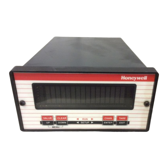
Honeywell SC1000 Manuals
Manuals and User Guides for Honeywell SC1000. We have
1
Honeywell SC1000 manual available for free PDF download: Owner's Manual
Honeywell SC1000 Owner's Manual (174 pages)
Sensotec Sensors Signal Conditioning, Self-Calibrating Digital Indicators
Brand:
Honeywell
| Category:
Accessories
| Size: 4.14 MB
Table of Contents
Table of Contents
3
Contents
3
Chapter 1 Introduction
9
About this Manual
9
Scope
9
Conventions
9
Organization
9
Related Documents
11
What Is the SC Series
12
Features
12
Chassis Models
12
Channel Types
12
What Is Signature Calibration
14
Overview
14
Benefits
14
Information Stored
14
Chapter 2 Getting Started Quickly
15
Locate Required Parts and Information
15
Connect the Transducer to the Correct Channel of the Instrument
15
Turn on the Instrument
16
Use the SETUP Menus to Enter Transducer Information
17
Calibrate the Transducers to Their Channels
17
The SC Series Instrument Is Ready for Use
17
Chapter 3 Operating Modes
19
INITIALIZE Mode
19
RUN Mode
20
Display
20
VALUE] Button
20
CLEAR] Button
20
CHANNEL] Button
21
TARE] Button
21
Indicator Lights
21
ERROR Mode
22
SETUP Menu Mode
23
Available Menus
23
Entering and Exiting the SETUP Menu Mode
23
Moving through SETUP Menus and Menu Items
23
Exiting the SETUP Menu Mode
23
Chapter 4 Chassis Models
25
Introduction
25
Specifications
26
Models SC1000 and SC2000
27
Differences
27
External Arrangement
27
Rear Panel
27
Panel Mounting
27
Rack Mounting
28
Bench Mounting
28
Case Removal
28
Internal Arrangement
29
Cleaning
30
Vehicle Power Option
30
Fuse Replacement
30
Model SC2001
31
Differences
31
External Arrangement
31
Front Panel
31
Case Removal
31
Internal Arrangement
32
Cleaning
32
Vehicle Power Option
32
Fuse Replacement
32
Model SC3004
33
External Arrangement
33
Rear Panel
33
Panel Mounting
33
Bench Mounting
33
Case Removal
34
Rear Panel
34
Internal Arrangement
34
Cleaning
34
Fuse Replacement
34
Chapter 5 System Connector
35
Introduction
35
System Connector Pinout
36
Function Input Pins
37
Overview
37
Example
37
Limit Output Pins
38
Overview
38
Example
38
Chapter 6 System Menu
41
Overview
41
Menu Items
41
SOFTWARE REVISION Menu Item
41
CONFIGURATION Sub-Menu
41
DIAGNOSTICS Sub-Menu
41
INSTALL CHANNEL Menu Item
42
DELETE CHANNEL Menu Item
44
DEFAULT CHANNEL Menu Item
44
Chapter 7 Serial Communications
47
Overview
47
Wiring
47
Communications Protocol
48
Vs. RS-485
48
Parameters
48
Serial Com Menu
49
Overview
49
INTERFACE Menu Item
49
ADDRESS Menu Item
49
BAUD RATE Menu Item
49
AUTO LINE-FEED Menu Item
49
TRANSMIT TEST Menu Item
49
LEAVE MENU Menu Item
49
Chapter 8 Display Menu
51
Overview
51
Menu Items for Models SC1000, SC2000, SC2001
51
UPPER CHANNEL Menu Item
51
LOWER CHANNEL Menu Item
51
LOWER MODE Menu Item
51
DISPLAY DISABLE Menu Item
51
Menu Items for Model SC3004
51
POWER-ON CHANNEL Menu Item
51
Chapter 9 Limits
53
Understanding Limits, Set Points and Return Points
53
Limit Operation
54
Actions When Activated
54
Scan Time
54
Limit Menus
55
Overview
55
LIMIT.ENABLE Menu Item
55
LIMIT.SETPOINT Menu Item
55
LIMIT.RETURN PNT Menu Item
55
LIMIT.ENERGIZE Menu Item
55
LIMIT.LATCHING Menu Item
57
LIMIT.CHANNEL Menu Item
57
LIMIT.SOURCE Menu Item
57
LEAVE MENU Menu Item
57
Chapter 10 Strain-Gage Input Channel
59
Features
59
Wiring
60
Calibration Procedure
61
Specifications
62
Channel Menu
63
OPERATION Sub-Menu
63
DISPLAY SETUP Sub-Menu
65
Auxn FUNCTION Menu Items
66
CALIBRATION TYPE Menu Item
67
CALIBRATION DATA Sub-Menu
69
CALIBRATE Menu Item
71
DAC SETUP Sub-Menu
73
SIGNATURE MODULE Sub-Menu
74
DIAGNOSTICS Sub-Menu
75
Analog Output Configuration
76
Identifying the Output Type
76
Channel Menu Items
76
Output Selection
76
Troubleshooting
77
Error Messages
77
Common Problems and Solutions
77
Chapter 11 AC/AC-LVDT Input Channel
79
Features
79
Wiring
80
Calibration Procedure
81
Specifications
82
Channel Menu
83
OPERATION Sub-Menu
83
DISPLAY SETUP Sub-Menu
85
Auxn FUNCTION Menu Items
85
CALIBRATION TYPE Menu Item
87
CALIBRATION DATA Sub-Menu
88
CALIBRATE Menu Item
89
DAC SETUP Sub-Menu
91
DIAGNOSTICS Sub-Menu
92
Electrical Null and Transducer Mounting
93
Overview
93
Procedure
93
Analog Output Configuration
94
Identifying the Output Type
94
Channel Menu Items
94
Output Selection
94
Troubleshooting
95
Error Messages
95
Common Problems and Solutions
95
Chapter 12 High-Level Input Channel
97
Features
97
Wiring
98
Channel Connector
98
Bi-Polar Voltage Amplifiers
99
3-Wire Voltage" Amplifiers
100
3-Wire Voltage" Amplifiers with Single-Wire Shunt Cal
101
3-Wire Current" Amplifiers
102
2-Wire Current" Amplifiers with Buffered Shunt Cal
103
2-Wire Current" Amplifiers with Single-Wire Shunt Cal
104
Low Voltage DC-DC Lvdts
105
Excitation and Signal Jumpers
106
Overview
106
Setting Jumpers
106
Calibration Procedure
107
Specifications
108
Channel Menu
109
OPERATION Sub-Menu
109
DISPLAY SETUP Sub-Menu
111
Auxn FUNCTION Menu Items
112
CALIBRATION TYPE Menu Item
113
CALIBRATION DATA Sub-Menu
115
CALIBRATE Menu Item
117
DAC SETUP Sub-Menu
119
DIAGNOSTICS Sub-Menu
120
Analog Output Configuration
121
Identifying the Output Type
121
Channel Menu Items
121
Output Selection
121
Troubleshooting
122
Error Messages
122
Common Problems and Solutions
122
Chapter 13 Relay Output Channel
123
Features
123
First Channel Installed
123
Second Channel Installed
123
Third Channel Installed
123
Fourth Channel Installed
123
Wiring
124
Setup Procedure
125
Specifications
126
Channel Menu
127
DIAGNOSTICS Sub-Menu
127
Chapter 14 DAC Output Channel
129
Features
129
Wiring
130
Setup Procedure
131
Specifications
132
Channel Menu
133
DAC SETUP Sub-Menu
133
DIAGNOSTICS Sub-Menu
134
Analog Output Configuration
135
Identifying the Output Type
135
Channel Menu Items
135
Output Selection
135
Troubleshooting
136
Error Messages
136
Common Problems and Solutions
136
Chapter 15 Split Display Virtual Channel
139
Features
139
Wiring
139
Setup Procedure
139
Channel Menu
140
Troubleshooting
140
Chapter 16 Mathematics Virtual Channel
143
Features
143
Wiring
144
Setup Procedure
145
Channel Menu
146
SENSOCODE P/N Menu Item
146
USER VALUES Sub-Menu
146
VIEW SENSOCODE Menu Item
146
VIEW COMMANDS Sub-Menu
146
DISPLAY SETUP Sub-Menu
147
POWER-ON SOURCE Menu Item
148
Troubleshooting
149
Chapter 17 Error Messages
151
Overview
151
Error Message List
152
Chapter 18 Setup Menu Reference
157
Navigation Instructions
157
Index
169
Warranty
173
Advertisement
Advertisement
Related Products
Honeywell SC3004
Honeywell SC2000
Honeywell SC2001
Honeywell SmartVFD
honeywell SHKC8M
Honeywell SMB10
Honeywell SMB10C
Honeywell GENT S4-770
Honeywell GENT S4-715
Honeywell GENT S4-710
Honeywell Categories
Thermostat
Controller
Control Unit
Security Camera
Accessories
More Honeywell Manuals
Login
Sign In
OR
Sign in with Facebook
Sign in with Google
Upload manual
Upload from disk
Upload from URL