
Related Manuals for ABB OMD800


Summary of Contents for ABB OMD800
- Page 1 — I N S TA L L AT I O N A N D O P E R AT I N G I N S T R U C T I O N Automatic control unit OMD800...
- Page 2 A U T O M AT I C C O N T R O L U N I T, O M D 8 0 0...
-
Page 3: Table Of Contents
Control circuit 5.2.1 Control circuit diagram OMD800 with motorized OTM40...125_CMA_ 5.2.2 Control circuit diagram OMD800 with motorized OTM160...2500_CM_ 20−21 5.2.3 OMD800 outputs 5.2.4 OMD800 inputs Operating Automatic control unit OMD800 in Manual Mode 23−25 Automatic control unit OMD800 in Automatic Mode... - Page 4 7.2.1 Menu browsing keys 7.2.2 Display 29−53 7.2.3 OMD800 communication via Modbus 53−61 Technical data of the automatic control unit OMD800 Troubleshooting OMD800 63−65 Explanations of internal faults OMD800 Change-over switch does not respond Missing of both lines Accessories 10.1 Fastener 10.2...
-
Page 5: Introduction
A U TO M AT I C C O N T R O L U N I T, O M D 8 0 0 — Introduction This manual describes the installation and the basic operation of the OMD800 automatic control unit. The in- structive part is followed by a section on available accessories. —... -
Page 6: Product Overview
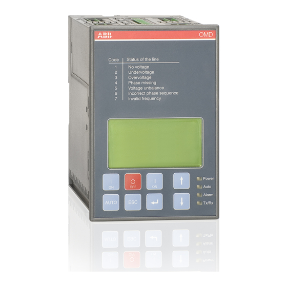
The OMD800 has two sensors to monitor two power lines; both sensors are able to work with single phase or three-phase lines. This unit can be supplied with an external auxiliary power supply. Monitor- ing, configuration and control are possible via Modbus RTU connection. -
Page 7: Typical Applications 07−08
A U TO M AT I C C O N T R O L U N I T, O M D 8 0 0 — Typical applications A. Mains – Generator line In case of loss of the primary power line, the OMD800 device manages the switching to the emergency power line equipped with a genset system. Figure 2.2 Mains - Generator line B. - Page 8 LINE 2 L1 N Figure 2.4 OMD800 have the capability to monitor two three-phase power lines, both able to work with single phase, too. OMD800 has an external auxiliary power supply possibility for guarantying an uninterrupted power supply for the device in the case where the Line 1 and Line 2 are not available.
-
Page 9: Description
— Description — OMD800 switching sequence 3.1.1 Line 1 priority The switching sequence of OMD800 can be summarized in following steps: An anomaly occurs on the Line 1 Switching delay Generator start Delay on transfer If Pre-transfer signal active: Pre-trasnfer signal output on,... -
Page 10: No Line Priority
A U T O M AT I C C O N T R O L U N I T, O M D 8 0 0 — 3.1.2 No line priority The switching sequence of OMD800 can be summarized in following steps: An anomaly occurs on the Line 1 Switching delay Generator start... -
Page 11: Line 2 Priority
A U TO M AT I C C O N T R O L U N I T, O M D 8 0 0 — 3.1.3 Line 2 priority The switching sequence of OMD800 can be summarized in following steps: An anomaly occurs on the Line 2 Switching delay If Pre-transfer signal active:... -
Page 12: Manual Back Switching Mode
A U T O M AT I C C O N T R O L U N I T, O M D 8 0 0 — 3.1.4 Manual back switching mode The switching sequence of OMD800 can be summarized in following steps: An anomaly occurs on the Line 1 Switching delay Generator start... -
Page 13: Installation
A U TO M AT I C C O N T R O L U N I T, O M D 8 0 0 — Installation — Dimensional drawings OMZD1 ×2 Figure 4.1 OMD800, dimensions of the device... -
Page 14: Mounting
4.2.1 Door mounting The automatic control unit OMD800 can be mounted on the door with the fastener OMZD1, see Acces- sories, Section 10. Door drilling according to Figure 4.2. As an optional extra you can use the cover plate OMZC2 on the door for OMD800, see Figure 4.3 on next page and Accessories, Section 10. - Page 15 A U TO M AT I C C O N T R O L U N I T, O M D 8 0 0 OMZC2 OMZD1 ×2 OMZD1 3,5×8 TX15 0,8 Nm ×8 O M D O M Figure 4.3 Automatic control unit OMD800, door mounting with the cover plate, door drilling for the cover plate OMZC2, see Accessories, Section 10...
-
Page 16: Din-Rail Mounting 16−17
4.2.2 DIN-rail mounting The automatic control unit OMD800 can be mounted on the 35 mm DIN-rail, see the Figure 4.4. Door drilling, if needed, according to Figure 4.4. As an optional extra you can use the cover plate OMZC2 on the door for OMD800, see Figure 4.5 and Accessories, Section 10. - Page 17 A U TO M AT I C C O N T R O L U N I T, O M D 8 0 0 OMZC2 O M D O M D 3,5×8 TX15 0,8 Nm ×8 Figure 4.5 Automatic control unit OMD800, DIN-rail mounting with the cover plate, door drilling for the cover plate OMZC2, see Accessories, Section 10...
-
Page 18: Connecting
A U T O M AT I C C O N T R O L U N I T, O M D 8 0 0 — Connecting Only an authorised electrician may perform the electrical installation and maintenance of OTM_ automatic transfer switches. Do not attempt any installation or maintenance actions when an OTM_ automatic transfer switch is connected to the electrical mains. -
Page 19: Control Circuit Diagram Omd800 With Motorized Otm40
A U TO M AT I C C O N T R O L U N I T, O M D 8 0 0 — Control circuit 5.2.1 Control circuit diagram OMD800 with motorized OTM40...125_CMA Figure 5.1 Control circuit diagram OMD800 with motorized OTM40…125_CMA_... -
Page 20: Control Circuit Diagram Omd800 With Motorized Otm160
A U T O M AT I C C O N T R O L U N I T, O M D 8 0 0 5.2.2 Control circuit diagram OMD800 with motorized OTM160...2500_CM_ Figure 5.2 Control circuit diagram OMD800 with motorized OTM160…2500_CM_... - Page 21 A U TO M AT I C C O N T R O L U N I T, O M D 8 0 0 Connectors, OMD800 Figure 5.3 Connectors, OMD800 Con- Description Con- Description nec- nec- X29:1 Emergency/Alarm, NO (Programmable)
-
Page 22: Omd800 Outputs
5.2.4.2 Force manual, X31:1 (DI3) When the handle is attached this input is closed and OMD800 is forced to Manual Mode. To set the OMD800 back to the Automatic Mode the handle must be removed and the AUTO key pushed (Auto LED is ON). -
Page 23: Operating
— 6.1 Automatic control unit OMD800 in Manual Mode Selecting the automatic control unit OMD800 to the Manual Mode: Make sure that power LED is ON, see the Figure 4.1/j. If Auto LED is OFF /k, the automatic control unit is in Manual Mode. - Page 24 A U T O M AT I C C O N T R O L U N I T, O M D 8 0 0 To select the operating line by the automatic control unit OMD800 in Manual Mode: Push the appropriate I, O or II key.
-
Page 25: Automatic Control Unit Omd800 In Automatic Mode
— 6.2 Automatic control unit OMD800 in Automatic mode Selecting the automatic control unit OMD800 to the Automatic Mode: Make sure that power LED is ON. If Auto LED is ON/ , the automatic control unit is in Automatic Mode. -
Page 26: Using Automatic Control Unit Omd800
O key Setting the motorized change-over switch OTM_C to the OFF position in manual and auto mode; both switches (I and II) are in the OFF position. After pressing the O-key the automatic control unit OMD800 is always in manual mode. -
Page 27: Leds
An active alarm is set off by pushing the AUTO key. Auto A green Auto LED signals the automatic or the manual mode. When the automatic control unit OMD800 is in automatic mode, the Auto LED is ON. When the device is in manual mode,the Auto LED is OFF. In test sequence the Auto LED is blinking. -
Page 28: Configuration
7.2.1 Menu browsing keys There are four menu browsing keys to operate the automatic control unit OMD800 from the display. Enter is used to enter a new menu page and to accept function ECS is used to exit a menu page... -
Page 29: Display 29−53
A U TO M AT I C C O N T R O L U N I T, O M D 8 0 0 7.2.2 Display The display is a graphic display with following menu pages: 7.2.2.1 Default page From default page the user can monitor following statuses: •... - Page 30 A U T O M AT I C C O N T R O L U N I T, O M D 8 0 0 During delay the name of the delay and residual time is shown in default page. When the device is used in Local –mode, the letter L is in the default page in right lower corner.
- Page 31 A U TO M AT I C C O N T R O L U N I T, O M D 8 0 0 7.2.2.3 System Configuration In the System Configuration subpage user can configure parameters of the monitored lines; see Table 7.3.
- Page 32 A U T O M AT I C C O N T R O L U N I T, O M D 8 0 0 Rated Voltage Rated Voltage is the rated voltage of the system. Value is announced as main voltage/phase voltage, Volts.
- Page 33 A U TO M AT I C C O N T R O L U N I T, O M D 8 0 0 External Voltage Transformer User can choose whether the voltage transformers are used in measured lines or not. When the external voltage transformers are present user must set also parameters Ext VT Primary Voltage and Ext VT Secondary Voltage according to transformer ratio.
- Page 34 A U T O M AT I C C O N T R O L U N I T, O M D 8 0 0 Output relay X24 (see control circuit diagram, Section 5.2) operates in two cases: Secondary Load parameter value is Opening Only or Opening Pulse and OMD800 automatic control unit performs switching sequence...
- Page 35 Manual Back Switching, Off is the default Generator Shutdown With this parameter user can choose between two strategies how OMD800 operates after receiving a generator alarm. If the Generator Shutdown is set to On, the generator stop command will be sent im- mediately after receiving the generator alarm.
- Page 36 A U T O M AT I C C O N T R O L U N I T, O M D 8 0 0 7.2.2.4 Device Configuration In the Device Configuration subpage user can configure programmable digital inputs and outputs, the thresholds and hysteresis for voltage and frequency, the delay times and the MODBUS communication protocol.
- Page 37 A U TO M AT I C C O N T R O L U N I T, O M D 8 0 0 Parameter Values Digital Inputs Digital Input 4 Digital Input 5 Digital Input 6 Digital Input 7 Digital Input 8 Digital Input 9 Digital Input 10...
- Page 38 A U T O M AT I C C O N T R O L U N I T, O M D 8 0 0 Parameter Values Language Selection English Deutsch Francais Italiano Espanol Suomi Russian Chinese Change Password Retype New Password INVALID PASSWORD PASSWORD CHANGED Table 7.4...
- Page 39 A U TO M AT I C C O N T R O L U N I T, O M D 8 0 0 Digital Inputs 4-7, Function Function Description No function Digital input disabled Emergency stop Digital input to command changeover switch to position O in case of emergency, overrides all other commands Inhibit switching I to II Digital input to prevent switching from Line 1 to Line 2...
- Page 40 A U T O M AT I C C O N T R O L U N I T, O M D 8 0 0 Digital Outputs User can configure Function and Contact Type (NO/NC) for Digital Outputs 6-10 and Digital Output 12. Available functions are described in Table 7.6.
- Page 41 A U TO M AT I C C O N T R O L U N I T, O M D 8 0 0 Digital Outputs 6-10 and 12, Contact status Contact type Contact type Function Function status Contact status No function Digital output disabled Emergency/alarm...
- Page 42 A U T O M AT I C C O N T R O L U N I T, O M D 8 0 0 Voltage Thresholds User can set separately Line 1 and Line 2 voltage thresholds both minimum and maximum values. Factory settings are min -20 % and max +20 %.
- Page 43 A U TO M AT I C C O N T R O L U N I T, O M D 8 0 0 Voltage Hysteresis User can set separately Line 1 and Line 2 voltage hysteresis both minimum and maximum values. Factory settings are min -19 % and max +19 %.
- Page 44 A U T O M AT I C C O N T R O L U N I T, O M D 8 0 0 Frequency Thresholds User can set separately Line 1 and Line 2 frequency thresholds both minimum and maximum values. Factory settings are min -1% and max 1%.
- Page 45 A U TO M AT I C C O N T R O L U N I T, O M D 8 0 0 Frequency Hysteresis User can set separately Line 1 and Line 2 frequency hysteresis both minimum and maximum values. Factory settings are min -0.8 % and max 0.8 %.
- Page 46 A U T O M AT I C C O N T R O L U N I T, O M D 8 0 0 Delay Times User can set delay times for Switching delay (Ts), Delay on Transfer (Tt), Pre-transfer I to II (Tp), Dead Band I to II (Ds), Back Switching delay (TBs), Pre-transfer II to I (TBp), Dead Band II to I (DBs), and Generator Stop delay (Gs).
- Page 47 Edit Figure 7.41 Auto Switch to O, Off is the default Both OMD800 and motor operator of the change-over switch need to be energized to en- able the automatic switching to position O. LCD Backlight Timer User can choose when to switch off the LCD backlight after the latest user interaction.
- Page 48 A U T O M AT I C C O N T R O L U N I T, O M D 8 0 0 Modbus User can set Address, Baud Rate, Stop Bits, Parity and Local/Remote for the Modbus. When Local is used device can’t be neither controlled nor configured through Modbus, only monitoring is possible.
- Page 49 A U TO M AT I C C O N T R O L U N I T, O M D 8 0 0 Tx/Rx LED indicates data transmission: LED is blinking only when data is transmitted from the OMD800. 10/12...
- Page 50 A U T O M AT I C C O N T R O L U N I T, O M D 8 0 0 Language Selection In this page it is possible to choose the Language. The choices are English, French, Italian, Spanish, Finnish, German, Russian and Chinese.
- Page 51 A U TO M AT I C C O N T R O L U N I T, O M D 8 0 0 7.2.2.5 Diagnostics Under Diagnostics are submenus: Measured Values, Alarm/Event Log, Counters, Generator Control, Test Sequence and Secondary Loads. Attribute Value Measured Values...
- Page 52 On this page the user can start or stop the generator if generator is in use (see the selection of “Generator Usage” in Section 7.2.2.3). Start and Stop commands are given with UP and DOWN arrow keys. OMD800 must be on Manual mode when starting the generator manually. Return back to Diagnostics menu by pushing the ESC key.
-
Page 53: Omd800 Communication Via Modbus 53−61
Test Sequence carries out the automatic switching sequence with delay times and generator control. The OMD800 has to be in manual mode to start the Test Sequence. When user starts the Test Sequence the device blinks LEDs (Power, Auto, Alarm) twice and returns to default page to show the status of the change-over switch, delay times and generator. - Page 54 A U T O M AT I C C O N T R O L U N I T, O M D 8 0 0 Information of registers, values and access is available in following table: Register Address Values REG_CONTROL 1 = Reset 10 = Change-over switch to position I 11 = Change-over switch to position O...
- Page 55 A U TO M AT I C C O N T R O L U N I T, O M D 8 0 0 Register Address Values REG_I_STATUS 0 = Open 1 = Closed REG_II_STATUS 0 = Open 1 = Closed REG_SL_STATUS 0 = Disconnected 1 = Connected...
- Page 56 A U T O M AT I C C O N T R O L U N I T, O M D 8 0 0 Register Address Values REG_SLAVE_ID Fixed value 49 REG_SW_VERSION Bits 8-15 = SW Version number in ASCII format Bits 0-7 = SW Version letter in ASCII format REG_OPERATION_COUNTER...
- Page 57 A U TO M AT I C C O N T R O L U N I T, O M D 8 0 0 Register Address Values REG_RATED_FREQUENCY 1 = 50 Hz 2 = 60 Hz REG_SECONDARY_LOAD 0 = Not Used 1 = Opening Only 2 = Opening And Closing 3 = Opening Pulse...
- Page 58 A U T O M AT I C C O N T R O L U N I T, O M D 8 0 0 Register Address Values REG_EXT_VT_SECONDARY 0 = 100/57 V 1 = 115/66 V 2 = 120/70 V 3 = 208/120 V 4 = 220/127 V 5 = 230/132 V...
- Page 59 A U TO M AT I C C O N T R O L U N I T, O M D 8 0 0 Register Address Values REG_DI4_CONTACT_TYPE 0 = NO 1 = NC REG_DI5_CONTACT_TYPE See REG_DI4_CONTACT_TYPE values REG_DI6_CONTACT_TYPE See REG_DI4_CONTACT_TYPE values REG_DI7_CONTACT_TYPE See REG_DI4_CONTACT_TYPE values REG_DI8_CONTACT_TYPE...
- Page 60 A U T O M AT I C C O N T R O L U N I T, O M D 8 0 0 Register Address Values REG_DELAY_TS 0...60 s REG_DELAY_DS 0...60 s REG_DELAY_TBS 0...5400 s REG_DELAY_DBS 0...60 s REG_DELAY_GS 0...1800 s REG_DELAY_TT...
- Page 61 A U TO M AT I C C O N T R O L U N I T, O M D 8 0 0 Register Address Values REG_ALARM_EVENT_LOG_41 2041 Alarm / Event Log item 41 REG_ALARM_EVENT_LOG_42 2042 Alarm / Event Log item 42 REG_ALARM_EVENT_LOG_43 2043 Alarm / Event Log item 43...
-
Page 62: Technical Data Of The Automatic Control Unit Omd800
5 % - 98 % without condensation 5 % - 90 % If 1 phase system is used and the voltage level is between 57,7 Vac - 109 Vac the auxiliary power supply (AUX) must be used. Table 8.1 Technical Data of OMD800... -
Page 63: Troubleshooting Omd800 63−65
External External malfunction Check the device connected to the external alarm input 1024 Alarm Generator Generator Check generator according to instructions provided by 4096 Alarm malfunctioning. the manufacturer. Table 9.1 Alarms in OMD800... - Page 64 A U T O M AT I C C O N T R O L U N I T, O M D 8 0 0 Events are explained in the table below: Message Description Value LN1 No Voltage No voltage on line I LN1 Undervoltage Undervoltage on line I LN1 Overvoltage...
- Page 65 Event initiated by digital input Table 9.3 Event operating mode and source information Event/Alarm Log can be read through Modbus registers (see 7.2.3 OMD800 communication via Modbus). Return value of the register can be interpreted as following: Alarm/Event flag Event value...
-
Page 66: Explanations Of Internal Faults Omd800
Missing of both lines The missing of both lines is indicated by a blinking Power LED. In this case, the OMD800 will be in a power saving state. If both lines are missing more than one minute, the OMD800 will shut down. -
Page 67: Accessories
A U TO M AT I C C O N T R O L U N I T, O M D 8 0 0 — 10 Accessories — 10.1 Fastener OMZD1 ×2 O M D O M D Figure 10.1 Fastener OMZD1, used when the automatic control unit OMD800 is mounted on the door... - Page 68 Cover plate OMZC2 IP54 91,0 OM D OM 120,0 OMZD1 3,5×8 TX15 0,8 Nm ×8 Ø 4 mm Figure 10.2 Door drilling and mounting of the cover plate OMZC2 , when the automatic control unit OMD800 is mounted on the door...
- Page 69 A U TO M AT I C C O N T R O L U N I T, O M D 8 0 0 OMZC2 IP54 91,0 OM D 120,0 OM D 3,5×8 TX15 0,8 Nm ×8 Ø 4 mm Figure 10.3 Door drilling and mounting of the cover plate OMZC2 , when the automatic control unit OMD800 is mounted on the DIN-rail...
- Page 70 A U T O M AT I C C O N T R O L U N I T, O M D 8 0 0...
- Page 71 A U TO M AT I C C O N T R O L U N I T, O M D 8 0 0...
- Page 72 — Contact us ABB Oy P.O. Box 622 FI-65101 Vaasa Finland abb.com/lowvoltage © Copyright 2020 ABB. All rights reserved. Specifications subject to change without notice.