Table of Contents
Advertisement
Quick Links
Advertisement
Table of Contents

Related Manuals for Draytek VigorAccess-A48M-2-SFP-A-1-AC


Summary of Contents for Draytek VigorAccess-A48M-2-SFP-A-1-AC
- Page 2 User’s Guide...
- Page 3 VigorAccess-A48M-2-SFP-A-1-AC ADSL2/2+ IP DSLAM User’s Guide Version: 1.0 Date: 25/06/2009 This manual is available for Vigor Access with Annex A (Annex M and Annex L)/Annex B. User’s Guide...
- Page 4 Copyright Information Copyright Copyright 2009 All rights reserved. This publication contains information that is Declarations protected by copyright. No part may be reproduced, transmitted, transcribed, stored in a retrieval system, or translated into any language without written permission from the copyright holders. The following trademarks are used in this document: Trademarks Microsoft is a registered trademark of Microsoft Corp.
- Page 5 No. 26, Fu Shing Road, HuKou Township, HsinChu Industrial Park, Hsin-Chu, Taiwan VigorAccess IP DSLAM A48 Product: DrayTek Corp. declares that VigorAccess is in compliance with the following essential requirements and other relevant provisions of R&TTE Directive 1999/5/EEC. The product conforms to the requirements of Electro-Magnetic Compatibility (EMC) Directive 2004/108/EC by complying with the requirements set forth in EN55022/Class A and EN55024/Class A.
- Page 6 Please prepare the following information before you contact your customer support. Product model and serial number Warranty information Date that you received VigorAccess Product configuration Software release version number Brief description of your problem The information of customer supports and sales representatives is in www.DrayTek.com, respectively. User’s Guide...
-
Page 7: Table Of Contents
Table of Contents 1. Introduction......................1 1.1 Features of VigorAccess ......................1 1.2 Applications ..........................6 1.2.1 General Application Scenario ..................7 1.2.2 Commercial Application Scenario ................. 8 1.3 Panel Explanation ........................9 2. Installation and Connection................11 2.1 Rack-Mounted Installation......................12 2.2 Desktop Placement ........................ - Page 8 A.2 Alarm Relay RJ45 Connector ....................52 A.3 Alarm Port RJ45 Connector ..................... 52 A.4 RS232 Connector ........................53 A.5 Standard 10/100 Base-T Ethernet Interface Connector ............54 A.6 Standard 10/100/1000 Base-T Ethernet Interface Connector ..........55 A.7 Contacting Your Dealer ......................55 User’s Guide viii...
-
Page 9: Introduction
1. Introduction With the explosive growth of Internet, people are becoming more and more relying on Internet in daily life. The rapidly increase in bandwidth demanded by digital society has put pressure on the network therefore, bandwidth and performance management are becoming critical issue for ISP. - Page 10 Ethernet Bridging IEEE 802.1d STD transparent bridging Up to 4000 MAC entries address table Port-based VLAN IEEE 802.1Q Tagged VLAN VigorAccess uses the IEEE 802.1Q Tagged VLAN; users can allow this device to deliver tagged/untagged frames in these ports. VigorAccess supports up to 512 VLAN groups and can be applied up to 4094 VLAN identifications.
- Page 11 Multiple PVC on single port VigorAccess allows you to use different virtual connection also called PVC (Permanent Virtual Circuits) for different services or subscribers. Users can define up to 8 connections on each DSL port for different services or levels of service, and users can assign different priority for each connection.
- Page 12 Mapping Table VigorAccess supports a packet priority to traffic class mapping table supported on a per egress bridge port. Multiple Mechanisms VigorAccess supports two multiple mechanisms as below. Multiple mechanisms of prioritizing incoming traffic are based on a per-bridge port. Using Source Port configuration (for untagged packets) Using Packet Classifier actions Using priority regeneration table (mapping ingress priority to egress priority)
- Page 13 Access Control List by IP Address This feature still can be configured by per-port, and enabled/disabled on a per bridge port basis. Packet Filtering This function is provided for users to setup some rules to filter the specific packets while receiving packets from logical ports.
-
Page 14: Applications
1.2 Applications The compact design of VigorAccess is composed of DSL, optical interfaces, and 2 subtend interfaces. VigorAccess provides lots of applications such as: High speed Internet Service - VigorAccess aggregates DSL subscribers and terminates the encapsulated type ATM cell. Users can easily access Internet through the IP backbone network. -
Page 15: General Application Scenario
1.2.1 General Application Scenario Take the following figure as an example. For users living in the same building, VigorAccess can set up additional Video Server, Mail Server, Proxy Server and Game Server in the network different from the ones set up by ISP, and allows users to share the multiple services. -
Page 16: Commercial Application Scenario
1.2.2 Commercial Application Scenario VigorAccess is able to support enterprise customer with high-speed service request. Customers can subscribe multiple ADSL 2/+ lines by integrating security router with load balance feature. By combining VoIP devices, system integrator provides multiple services with VoIP, Video on Demand, and ADSL2/+ bundle solution, etc. In addition, the firewall and VPN security of VoIP security router is also provided by the architecture to meet business requirements. -
Page 17: Panel Explanation
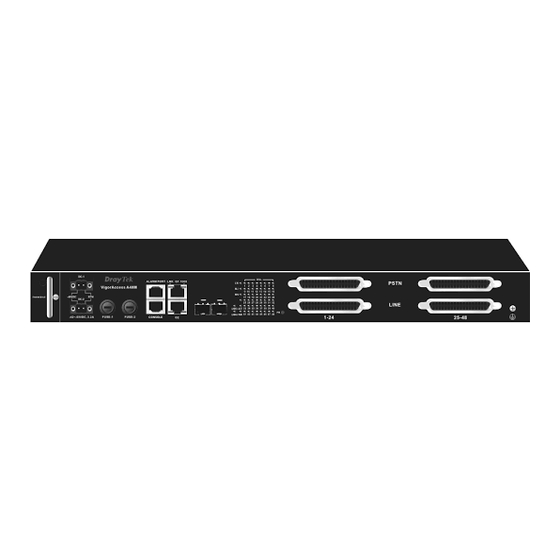
1.3 Panel Explanation The connectors on the front panel for the VigorAccess A48 is shown below: Interface Description Support hot-swappable FAN MODULE DC1 ~ DC2 DC power connector (dual feed) Fuse-1 maps to DC1 and Fuse-2 maps to DC2. FUSE-1 ~ FUSE-2 ALARM PORT An alarm relay with RJ45 interface can connect to buzzer when the... - Page 18 RJ45 Cable for G1 –G2 RJ-45 (8P8C), Connect to slave unit (UP1or UP2). Blue RJ-21, Grey RJ-21 Cable for MDF or Panel to PSTN. PHONE RJ-21 Cable for LINE RJ-21, Grey To subscriber copper line. LED Indication Status Explanation Subtend interface by GE Interface. Green When the Ethernet link is established, it will blink G1 –...
-
Page 19: Installation And Connection
2. Installation and Connection This section will guide you to install the VigorAccess through hardware connection To fully setup the VigorAccess connection, you have to finish the following items: Rack-mounted installation Line interface connection (ADSL port connection) Phone interface connection Below shows an example of VigorAccess network connection for your reference. -
Page 20: Rack-Mounted Installation
2.1 Rack-Mounted Installation VigorAccess can be installed on 19-, 23-inches racks by using standard brackets in 19-inch rack or optional larger brackets on 23-inch rack with other equipments. The bracket for 19-, 23-inch racks are shown below. Attach the brackets to the chassis in 19-, 23-inch rack. The second bracket attaches the other side of the chassis as above procedure. -
Page 21: Frame Ground Installation
2.3 Frame Ground Installation The frame ground is on the front of the VigorAccess which is powered by DC connector. Connect the frame ground to a building’s earthing terminal by using frame ground wire. Importance: Please connect the frame ground first before you connect any other cables for this device. -
Page 22: Adsl Port Connection
2.4 ADSL Port Connection 2.4.1 MDF (Main Distribution Frame) The PSTN splitter should be connected to MDF on building. An MDF is usually placed in the building’s telephony room or wiring closet. MDF can terminate the outside telephone line into the building. In general, the LINE and PHONE interface on the A48 device will connect to MDFs respectively and then to outside connection. -
Page 23: Scenario - Standalone
2.4.2 Scenario – Standalone A48 is used standalone for it cannot manage any slave device. In such condition, it can connect and control 24 ADSL CPE routers with DB-21 cable through MDF connection. In the above picture, the user of PC-3 wants to use phone and access the Internet at the same time;... -
Page 24: Scenario - Cascade Installation
2.4.3 Scenario – Cascade Installation For Master device and Slave device, at least there are 48 ADSL CPE routers can be connected to outside Internet via the Master device. The following picture shows the sample connection for A48 devices. Here we take PC-1, PC-2 and PC-3 as the examples that connecting to the Slave device directly and wanting to access the Internet through the Master device. - Page 25 With such connection, all the users of the PCs (connecting to Slave device) can access the Internet through fiber connector of the Master device. Yet only PC-3 can call out with a telephone set directly. Such connection allows 48 ADSL CPE routers to connect to outside Internet via the A48 device.
-
Page 26: Scenario - A24M And Six A48 Devices
2.4.4 Scenario – A24M and Six A48 Devices The following picture shows the sample connection between six A48 devices and one A24M device. Here we take PC-1, PC-2 and PC-3 as the examples that connecting to one A48 directly and wanting to access the Internet through A24M device. In the above picture, the user of PC-3 wants to use phone and access the Internet at the same time;... - Page 27 To make the required configuration for master and slave devices, use CLI command. Admin> dsl -m Press 'exit' to return Entering character mode Escape character is '^]'. [dsl-master]# Admin> dsl -s <n> Press 'exit' to return Entering character mode Escape character is '^]'. [dsl-slave-n]# User’s Guide...
-
Page 28: Cpp (Centric Patch Panel)
2.4.5 CPP (Centric Patch Panel) The VigorAccess can provide ADSL and voice services over the same telephone wiring. It also has built in splitters internally that can save space and simplify installation. If the application is using on building environment, the CPP (Centric Patch Panel) is preferred. - Page 29 Scenario B Phone service is available in VigorAccess. You can connect a RJ-11 jack port attached in a CPP to a telephone directly or applied in the same way shared in ADSL modem. The following example shows the connection for Data/Voice transmission through CPP. User’s Guide...
-
Page 30: Power Connection
2.5 Power Connection (Only DC Model) Before you purchasing the device, please check your environment to determine which power type that matches with your requirement. Get acquainted with the following parts first: DC Power Cord Y type terminator DC Power Terminator Head Follow the steps below to complete the power cord combination. - Page 31 Plug the power cord head into the DC-1/DC-2 connector on A48. Warning: The above figure shows the DC power supply terminal block. It is the lugs at the wiring end from the power source. The wiring procedure is for ground-to-ground, positive-to-positive, and negative-to-negative in order. The ground wire should always be connected first and disconnected last.
-
Page 32: Optical Fiber Connection (Sfp Optional)
2.6 Optical Fiber Connection (SFP Optional) Before you start to do the optical fiber connection, please read the following warnings first. Warnings: The laser energy of the fiber optic communication channels in the single-mode will be harmful when operate, especially to the eyes. During normal operation with cable connection, this energy is confined to the cable with no danger present. - Page 33 interface Short haul SX multi-mode Multi-mode (MM), 50/125 or 62.5/125-micron interface The two types of interface are visually and functionally similar. Installation procedures are the same. This dual port has both connectors on transmit (upstream) and a receiving (downstream) is shown below. Follow the steps below to connect the fiber channel: Read and understand the previous warnings and alarm.
-
Page 34: Console Port Connection
2.7 Console Port Connection The default setting of the console port is “baud rate 9600, no parity, and 8 bit with 1 stop bit (N81)”. For the initial configuration, users need to use terminal emulator software on a computer and connect it to a network module through the console port. Users can connect the RJ-45 end of the console cable to the console port of the network module. -
Page 35: Web Configuration
3. Web Configuration This chapter introduces you how to access IPDSLAM devices via WEB user interface. 1. Please upgrade new firmware at first. 2. Configure management IP address 3. Open browser to access IPDSLAM via Web pages as below: * Browse master control => http://[IP address] * Browse master dsl =>... -
Page 36: Status
Type the textual identification of the contact person for Contact such device, together with information on how to contact this person, e.g., “Mr. Lin, phone: +886 3 5972727 ext 123” . Type the vendor-specific information, e.g., “Draytek Vendor Taiwan”. Display the system up time. Up Time Type the version number of hardware. -
Page 37: Snmp Config
System Time Display current system time. Click Apply to save the settings Apply Click Cancel to cancel the configured settings and restore to the previous configuration. 3.1.2 SNMP Config The Simple Network Management Protocol (SNMP) is an application layer protocol that facilitates the exchange of management information between network devices. -
Page 38: Ip Config
3.1.3 IP Config The Internet Protocol (IP) is a protocol used for communicating data across a packet-switched internetwork using the Internet Protocol Suite, also referred to as TCP/IP. IP is the primary protocol in the Internet Layer of the Internet Protocol Suite and has the task of delivering distinguished protocol datagrams (packets) from the source host to the destination host solely based on their addresses. -
Page 39: Commit
This page allows users to upgrade firmware through a Web interface. In the System group, click the Firmware Upgrade option. You can see the following page then. Before you execute the firmware upgrade, please download the newest firmware from Draytek’s website (www.draytek.com) or FTP site (ftp.draytek.com) on the computer first. - Page 40 Firmware upgrade can be done from a console port, too. The following example was run on a Windows environment. Download the newest firmware from the DrayTek Website (www.draytek.com.tw) or FTP site (ftp.draytek.com) on your computer first. Connect the RJ45 connector of console cable to the console port on Vigor device and the DB9 connector of the console cable to the RS232 port on the PC.
- Page 41 Type the path name of the firmware image and activate the TFTP Client from the PC to download the image. The corresponding message is shown as follows: firmware upgrade <firmware firle name> all <tftp server ip > Now in the Console you will find the following information. When Updating flash block at bfXXXXXX appears, it means the firmware is under downloading.
-
Page 42: Configuration Backup/Restore
When Firmware Upgrade SUCCESSFUL appears, it means the firmware upgrading is finished. User should reboot it manual. 3.1.8 Configuration Backup/Restore Most of the settings can be saved locally as a configuration file, and can be applied to another router. VigorAccess supports the restore and upload functions of the configuration files. - Page 43 Restore Click this button to restore the previous saved configuration file and apply to the device. Click this button the backup current configuration file. Backup User’s Guide...
-
Page 44: Dsl Configuration
3.2 DSL Configuration This page is used for DSL related configuration. Line profile configures train rate, SNR, and etc. DSL show can display current DSL training status. Performance shows different type of error counts during Curr15Min/Curr1Day/Prev1Day. 有修改,請幫我再看看 3.2.1 Line Profile This page allows you to configure line profile parameters for the selected port. - Page 45 Fast Max TX Rate (bps) - Configure Maximum Transmit rate for 'Fast' channel, in bps. Fast Min TX Rate (bps) - Configure Minimum Transmit rate for 'Fast' channel, in bps. Downstream/Upstream SNR Margin DSL Downstream/Upstream (Singal to Noise Ratio)SNR related parameter: Target SNR Margin - the modem must achieve with a BER of 10 to the power 7 or better to successfully complete initialization for Noise Margin.
- Page 46 GS Standard This parameter defines what DSL capability will be use after training. This parameter defines what ADSL annex standard to be Annex Type used. This parameter defines what frequency division mode to Dmt Config Mode be used. The lowest bin number allowed for upstream signal. Upstream Start Bin Upstream End Bin The highest bin number allowed for upstream signal.
-
Page 47: Dsl Show
PM mode PM-related parameter used by the ATU-C to set the allowed link states. disable – No power management. l2enable - The ADSL link is active, but a low-power signal conveying background data is sent from the ATU-C to the ATU-R. l3enable - There is no signal transmitted on the line and thus no transmission of information is possible. - Page 48 Mode It is used to select the ADSL physical line mode. Fast and Interleaved represent different algorithms for DSL data transmission. DSL Name Display DSL line name. OpState Display current operation status. Standard Display current used DSL standard. Display current down rate. DownRate UpRate Display current up rate.
-
Page 49: Performance
ATUR-SNR Display Noise Margin seen by this ATU with respect to its received signal in tenth dB in CPE side. Display the total output power transmitted by this ATU in ATUR-PWR CPE side. Display Noise Margin seen by this ATU with respect to its ATUR-ATN received signal in tenth dB in CPE side. -
Page 50: Pvc
A permanent virtual circuit (PVC) is a virtual circuit established for repeated/continuous use between the same data terminal equipments (DTE). PVC can be established as an option to provide a dedicated circuit link between two facilities. PVC configuration is usually pre-configured by the service provider. 3.3.1 PVC This page allows you to configure Virtual Path Identifier(VPI) and Virtual Circuit Identifier(VCI) for each PVC. - Page 51 MPOA Display the data encapsulation method used over the AAL5. Display the physical ADSL line mode. Channel Display the ATM interface name. Display the DSL interface name. Create Click this button to create a new PVC profile. Delete Click this button to delete the selected PVC profile. Creating a PVC Click Create to generate a new PVC profile.
-
Page 52: Mac Profile
profile. For more detailed of Mac Profile, please refer to 3.3.2. 3.3.2 Mac Profile MAC address profile is a generic way for assigning MAC addresses for certain interfaces. The MAC address can be associated with a profile, and that profile can be attached to interface. -
Page 53: Vlan
3.4.1 VLAN VLAN is a group of hosts with a set of requirements that communicate when they are attached to the Broadcast domain, regardless of their physical locations. In IPDSLAM, it supports up to 512 VLAN at one time. Serial Display the number of the VLAN profile. - Page 54 Bridging Mode Choose the mode for the selected VLAN used. Restricted –Switching of traffic from one CPE to another CPE is prohibited. In case traffic coming from one CPE / downlink is meant for another CPE / downlink, it is dropped - effectively achieving VLAN isolation between CPEs / stacked DSLAMs.
-
Page 55: Bridge
3.4.2 Bridge This page is for Bridge configuration including, 802.1P, IGMP leaved mode, QoS configuration, and Max Unicast address. Bridge Port Display the number of the profiles that system offered. 1 – 48 represents port 1 to port 48. Editing Bridge Profile Click the radio button of the profile you want to edit. - Page 56 Bridge Port Display the number of the profiles that you want to edit. Such number cannot be modified. The default ingress User Priority which can be configured 802.1P by the user. The default value of this attribute can be 0. The large number means first priority.
-
Page 57: Qos Profile
Max Unicast Addresses Configure max learned unicast addresses number. The default value is 64.Uplink port(193) default value is 256. Note: Bridge port is fixed and cannot be modified. If you want to change it, delete the profile and create a new one. 3.4.3 Qos Profile A profile with a set of parameters is used to quantify the quality of service provided. - Page 58 Editing QoS Profile Click the radio button of the profile you want to edit. Next, click Edit to open it. Below shows the detailed web page. Name Display the name of the profile. You can retype the name to modify it. PCR means Peak Cell Rate.
-
Page 59: Appendix A: Connectors
Appendix A: Connectors A.1 RJ21 DSL Connector Connections made with two 50-pin champ cables are attached to the RJ21 interface on VigorAccess. Each cable terminates with a 50-pin Telco straight champ connector. Pin 1 Pin25 Pin 26 Male Pin 50 Pin assignments between the Line and the PSTN splitter. -
Page 60: Alarm Relay Rj45 Connector
A.2 Alarm Relay RJ45 Connector RJ45 jets provide connection with an external alarm device to the alarm relay connector, The alarm relays provide relay contact closures. If you connect the alarm relays, they transmit critical, major, and minor alarms to a separate, external alarm device. The alarm device uses a bell, light, or some other signal to alert people of the change in status. -
Page 61: Rs232 Connector
The table below lists the pin assignments for backplane connector RJ45, the alarm relay connector. Signal Description RELAY NC RELAY NORMAL CLOSE CONTACT RELAY NO RELAY NORMAL OPEN CONTACT) RELAY COM (RELAY COMMON CONTACT) ALARM IN2 (ALARM INPUT CONTACT GROUP2) NOT USED ALARM IN1 (ALARM INPUT CONTACT GROUP1... -
Page 62: Standard 10/100 Base-T Ethernet Interface Connector
A.5 Standard 10/100 Base-T Ethernet Interface Connector RJ45 jets provide 10/100 Base-T Ethernet interfaces. The interface supports MDI/MDIX auto-detection of either straight or crossover RJ45 cables. These cables are used on UP1,UP2/MGN interfaces. At 400 and 600 W the surface roughness was quite low (~15 2) and the coatings showed a mirror-like surface with a high brightness. -
Page 63: Standard 10/100/1000 Base-T Ethernet Interface Connector
TP2- A.7 Contacting Your Dealer If the device you have still cannot work correctly after trying many efforts, please contact your dealer for further help right away. For any questions, please feel free to send e-mail to support@draytek.com. User’s Guide...