Table of Contents
Advertisement
Quick Links
Advertisement
Table of Contents

Related Manuals for Tripp Lite NGI-M08C4-L2


Summary of Contents for Tripp Lite NGI-M08C4-L2
- Page 2 COPYRIGHT All rights reserved. No part of this publication may be reproduced, stored in a retrieval system, or transmitted in any form or by any means, whether electronic, mechanical, photo copying, recording or otherwise, without the prior written permission of the publisher. FCC WARNING This equipment has been tested and found to comply with the limits for a class A device, pursuant to part 15 of FCC rules.
- Page 3 Take special care to read and understand all the content in the warning boxes. Warning Do not work on the system or connect or disconnect cables during periods of lightning activity. Warning Before working on equipment that is connected to power lines, remove jewelry (including rings, necklaces, and watches).
- Page 4 Read the wall-mounting instructions carefully before beginning installation. Failure to use the correct hardware or to follow the correct Warning procedures could result in a hazardous situation to people and damage to the system. Before performing any of the following procedures, ensure that power is removed from the DC circuit.
- Page 5 When installing or replacing the unit, the ground connection must always be made first and disconnected last. Warning Voltages that present a shock hazard may exist on Power over Ethernet (PoE) circuits if interconnections are made using uninsulated exposed Warning metal contacts, conductors, or terminals.
-
Page 6: Table Of Contents
1.1. W .......................... 15 ELCOME 1.1. P ..........................15 URPOSE 1.2. T ........................15 ERMS SAGE ABOUT THE NGI-M08C4-L2 .................... 16 2.1. F ........................... 16 EATURES 2.2. S ......................... 16 PECIFICATIONS HARDWARE DESCRIPTION ................... 19 3.1. C ........................19 ONNECTORS 3.2. - Page 7 5.2.1.2. W ..................... 46 ONFIGURATION 5.2.2. MAC T ........................48 ABLE 5.2.2.1. CLI C ...................... 48 ONFIGURATION 5.2.2.2. W ..................... 48 ONFIGURATION 5.2.3......................50 ETTINGS 5.2.3.1. CLI C ...................... 50 ONFIGURATION 5.2.3.2. W ..................... 50 ONFIGURATION 5.2.4. MAC) ..................51 EFUSAL LACK HOLE...
- Page 8 6.2.1.2.2 W ..................... 81 ONFIGURATION 6.2.1.3 Q ......................82 UERIER ETTINGS 6.2.1.3.1 CLI C ...................... 82 ONFIGURATION 6.2.1.3.2 W ..................... 83 ONFIGURATION 6.2.2 IGMP S ................... 84 NOOPING ILTERING 6.2.2.1 G ......................84 ENERAL ETTINGS 6.2.2.1.1 CLI C ....................84 ONFIGURATIONS 6.2.2.1.2 W ....................
- Page 9 6.3.3.1.2 W ....................115 ONFIGURATION 6.3.3.2 GARP T ......................... 116 IMER 6.3.3.2.1 CLI C ....................116 ONFIGURATION 6.3.3.2.2 W ....................116 ONFIGURATION 6.3.4 IP S VLAN ......................117 UBNET 6.3.4.1 CLI C ....................117 ONFIGURATION 6.3.4.2 W ....................118 ONFIGURATION 6.3.5 MAC- VLAN ......................
- Page 10 6.8.3.1 CLI C ....................158 ONFIGURATIONS 6.8.3.2 W ....................158 ONFIGURATIONS 6.9 L ......................159 ETECTION 6.9.1 CLI C ....................160 ONFIGURATION 6.9.2 ....................161 ONFIGURATION 6.10 M TCP ........................162 ODBUS 6.10.1 CLI C ....................166 ONFIGURATION 6.10.2 ....................166 ONFIGURATION 6.11 PTP (IEEE-1588 V2) .......................
- Page 11 6.14.4.4.1 CLI C ..................... 211 ONFIGURATIONS 6.14.4.4.2 W ................... 212 ONFIGURATIONS 6.15 UDLD ..........................213 6.15.1 ......................213 ETTINGS 6.15.1.1 CLI C ....................213 ONFIGURATIONS 6.15.1.2 W ....................216 ONFIGURATIONS 6.15.2 ........................217 EIGHBORS 6.15.2.1 CLI C ....................217 ONFIGURATIONS 6.15.2.2 W ....................
- Page 12 7.4.1 ......................251 ECURITY 7.4.1.1 CLI C ....................251 ONFIGURATIONS 7.4.1.2 W ....................252 ONFIGURATIONS 7.4.2 ........................252 TICKY 7.4.2.1 CLI C ....................253 ONFIGURATIONS 7.4.2.2 W ....................254 ONFIGURATIONS 7.5 TACACS+ .......................... 255 7.5.1 CLI C ....................256 ONFIGURATIONS 7.5.2 ....................
- Page 13 9.1.2.3 P ......................276 VENT 9.1.2.3.1 CLI C ....................276 ONFIGURATIONS 9.1.2.3.2 W ....................276 ONFIGURATIONS 9.1.3 SNMP 3 ........................277 9.1.3.1 G ......................277 ROUP ETTINGS 9.1.3.1.1 CLI C ....................277 ONFIGURATIONS 9.1.3.1.2 W ....................278 ONFIGURATIONS 9.1.3.2 U ......................
- Page 14 9.8.3.2 W ....................305 ONFIGURATIONS 9.9 T ........................ 307 OPOLOGY 9.9.1 ................... 309 ACKGROUND ONFIGURATION 9.9.2 ................... 310 LIENT WITCH ANAGEMENT 10. MISC ........................... 310 10.1 CABLE TEST ........................310 10.1.1 CLI CONFIGURATIONS ..................310 WARRANTY & PRODUCT REGISTRATION……………………………………………..312...
-
Page 15: About This Guide
This guide describes how to install and configure the NGI-M08C4-L2 Industrial Managed Switch. 1.2. Terms/ Usage In this guide, the term “Switch” (first letter upper case) refers to the NGI-M08C4-L2 Switch, and “switch” (first letter lower case) refers to other switches. -
Page 16: About The Ngi-M08C4-L2
2. About the NGI-M08C4-L2 2.1. Features Network Functions TACACS+ Port-based Mirroring Traffic management & QoS GARP/GVRP Support Port Priority 4K Active VLAN Rate Limitation IGMP Snooping v1/v2/v3 Storm Control IGMP Querier Port Isolation 802.1Q Tag-based VLAN DHCP Relay/Option 82 Auto MDI/MDI-X... - Page 17 IEEE 802.1p Class of Service IEEE 802.1X Port Authentication IEEE 802.1AB Link Layer Discovery Protocol IEEE 802.3ad Port Trunk with LACP ITU-T G.8032v1/v2 Ethernet Ring Protection Switching Performance Switching fabric 24Gbps L2 forwarding 17.86Mpps Packet Buffer size 8Mbits MAC Entries 16 K Jumbo frame 10 K...
- Page 18 DIN RAIL Recommendation Steel with Electrolytic Zinc Plating Stand-Off Brackets: 45 Angle and Straight Comply with DIN 50045, 50022 and 50035 Standards...
-
Page 19: Hardware Description
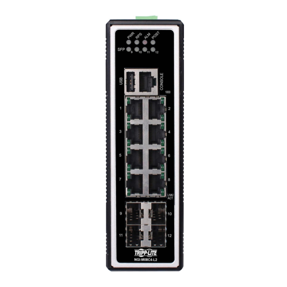
3. Hardware Description NGI-M08C4-L2 Front Panel 8 10/100/1000Base-T ports & 4 Gigabit SFP slots Managed Industrial Ethernet Switch 3.1. Connectors The Switch utilizes ports with copper and SFP fiber port connectors functioning under Ethernet/Fast Ethernet/Gigabit Ethernet standards. 10/100/1000Base-T Ports The 10/100/1000Base-T ports support network speeds of 10Mbps, 100Mbps or 1000Mbps, and can operate in half- and full-duplex transfer modes. -
Page 20: Installation
Hardware Installation Step 1: Unpack the device and other contents of the package. Step 2: Fasten DIN-Rail or Wall-mount kit on the rear of the NGI-M08C4-L2 Connect the 12~60V DC power to the PWR & RPS terminal block. - Page 21 Location: The NGI-M08C4-L2 can be DIN-Rail-mounted in cabinet or enclosure. Mounting the Switch Place the NGI-M08C4-L2 on the DIN rail from above using the slot. Push the front of the switch toward the mounting surface until it snaps into place with a click sound.
- Page 22 ATTENTION The product should be mounted in an Industrial Control Panel and the ambient temperature should not exceed 75°C. ATTENTION A corrosion-free mounting rail is advisable. When installing, make sure to allow for enough space to properly install the cabling. Wiring Power Inputs You can use “Terminal Block (PWR)”...
- Page 23 WARNING Safety measures should be taken before connecting the power cable Turn off the power before connecting modules or wires. The correct power supply voltage is listed on the product label. Check the voltage of your power source to make sure that you are using the correct voltage.
-
Page 24: Led Indicators
Check the front-panel LEDs as the device is powered on to verify that the Power LED is lit. If not, check that the power cable is correctly and securely plugged in. Notice: Turn off the power before connecting modules or wires. The correct power supply voltage is listed on the product label. -
Page 25: Usb Port
For example if you are running with Firmware version 1.0.0.S0 you need to upgrade the firmware to version 1.0.1.S0 then you need to follow these steps. Create a folder with model name in USB (eg: NGI-M08C4-L2) Note: don’t add ‘A’ in folder name. -
Page 26: Dip Switches
Switch updates itself to new firmware version, else it will be ignored for following conditions If there are more than one Firmware files existed If Firmware version is identical to the image on device After Upgrade Complete or Upgrade Ignored, Switch will download latest running configuration &... -
Page 27: System Status
4. System Status 4.1. Console Port Connect your computer to the console port on the Switch using the appropriate cable. Use terminal emulation software with the following settings: Default Settings for the Console Port Setting Default Value Terminal Emulation VT100 Baud Rate 38400... -
Page 28: Cli Command Concept
Input command “enable” L2SWITCH>enable Input a valid username and password when below prompt are displayed. user: admin password: admin L2SWITCH# 4.4. CLI Command concept Node Command Description enable show hostname This command displays the system’s network name. configure reboot This command reboots the system. eth0 ip address A.B.C.D/M This command configures a static IP and subnet mask for the system. -
Page 29: Gui Login
In Configure code, executing command “interface fastethernet1/0/5” enter the interface port 5 node. Note: depend on your port speed, gigaethernet1/0/5 for gigabit Ethernet ports and fastethernet1/0/5 for fast Ethernet ports. L2SWITCH(config)#interface gigaethernet1/0/5 L2SWITCH(config-if)# vlan Its command prompt is “L2SWITCH(config-vlan)#”. It means these commands can be executed in this command prompt. -
Page 30: Ystem Nformation
4.6. System Information 4.6.1. CLI Configuration Node Command Description enable show hostname This command displays the system’s network name. enable show interface eth0 This command displays the current Eth0 configurations. enable show model This command displays the system information. enable show running-config This command displays the current operating configurations. -
Page 31: Web Configuration
4.6.2. Web Configuration The System Information window appears each time you log into the program. Alternatively, this window can be accessed by clicking System Status > System Information Parameter Description System Information Model Name This field displays the model name of the Switch. Host name This field displays the name of the Switch. - Page 32 Version This field displays the version of primary firmware. Built Date This field displays the built date of primary firmware. Checksum This field displays the checksum of primary firmware. Secondary Firmware Version This field displays the version of secondary firmware. Built Date This field displays the built date of econdary firmware.
-
Page 33: Basic Settings
5. Basic Settings 5.1. General Settings 5.1.1. System Management VLAN To specify a VLAN group which can access the Switch. The valid VLAN range is from 1 to 4094. If you want to configure a management VLAN, the management VLAN should be ... - Page 34 eth0 ip ipv6-address This command configures a global scope of AAAA:BBBB:CCCC:DDDD:E IPv6 address and subnet mask for the system. EEE:FFFF:GGGG:HHHH/M eth0 ip ipv6-addressdefault-gateway This command configures a default gateway for AAAA:BBBB:CCCC:DDDD:E the system. EEE:FFFF:GGGG:HHHH eth0 ip ipv6-dhcp client This command configures a DHCPv6 client (disable|enable|renew| function for the system.
-
Page 35: Web Configuration
5.1.1.2. Web Configuration Parameter Description System Settings Enter up to 64 alphanumeric characters for the name of your Switch. Hostname The hostname should be the combination of the digit or the alphabet or hyphens (-) or underscores (_). Management Enter a VLAN ID used for Switch management purposes. VLAN DHCP Server Port Configures a port or a range of ports for valid DHCP server. - Page 36 Select Enable to allow the Switch to automatically get an IP address from a DHCPv6 server. Click Renew to have the Switch re-get an IP DHCPv6 Client address from the DHCP server. Select Disable if you want to configure the Switch’s IP address manually.
-
Page 37: Jumbo Frame
5.1.2. Jumbo Frame Jumbo frames are Ethernet frames with a payload greater than 1500 bytes. Jumboframes can enhance data transmission efficiency in a network. The bigger the frame size, the better the performance. Notice: The default jumbo frame is 10240 bytes. ... -
Page 38: Web Configuration
5.1.2.2. Web Configuration Parameter Description Jumbo Frame Settings Port This field specifies a port or a range of ports for configuration. This field configures the maximum number of bytes of frame size Frame Size for specified port(s). (available size:1522/1536/1552/9010/9216/10240) Click Apply to take effect the settings. Apply Refresh Click Refresh to begin configuring this screen afresh. -
Page 39: Cli Configuration
Notes: The SNTP server always replies the UTC current time. • When the Switch receives the SNTP reply time, the Switch will adjust the time with • the time zone configuration and then configure the time to the Switch. If the time server’s IP address is not configured, the Switch will not send any SNTP •... -
Page 40: Web Configuration
) MONTH HOUR configure time ntp-server (disable|enable) This command disables / enables the NTP server state. configure time ntp-server IP_ADDRESS This command sets the IP address of your time server. configure time ntp-server domain-name This command sets a domain name of your STRING time server. - Page 41 Parameter Description Current Time and Date Current Time This field displays the time you open / refresh this menu. Current Date This field displays the date you open / refresh this menu. Time and Date Setting Select this option if you want to enter the system date and time Manual manually.
- Page 42 select First, Sunday, November and 2:00. Daylight Saving Time ends in the European Union on the last Sunday of October. All of the time zones in the European Union stop using Daylight Saving Time at the same moment (1 A.M. GMT or UTC). So in the European Union you would select Last, Sunday, October and the last field depends on your time zone.
-
Page 43: Management Host
5.1.4. Management Host The feature limits the hosts which can manage the Switch. That is, any hosts can manage the Switch via telnet or web browser. If user has configured one or more management host, the Switch can be managed by these hosts only. The feature allow user to configure management IP based on particular IP or whole subnet. -
Page 44: Web Configuration
UP BROADCAST RUNNING ALLMULTI MULTICAST MTU:1500 Metric:1 ASYMMTU:0 RX packets:17931 errors:0 dropped:6680 overruns:0 frame:0 TX packets:6500 errors:0 dropped:0 overruns:0 carrier:0 collisions:0 txqueuelen:500 RX bytes:3565872 (3.4 Mb) TX bytes:1173040 (1.1 Mb) 5.1.4.2. Web Configuration Parameter Description Management Host Settings Management Host This field configures the management host. -
Page 45: Mac Management
5.2. MAC Management Dynamic Address: The MAC addresses are learnt by the switch. When the switch receives frames, it will record the source MAC, the received port and the VLAN in the address table with an age time. When the age time is expired, the address entry will be removed from the address table. -
Page 46: Static Mac
5.2.1. Static MAC 5.2.1.1. CLI Configuration Node Command Description This command displays the current static/dynamic enable show mac-address-table (static|dynamic) unicast address entries. enable configure terminal This command changes the node to configure node. configure mac-address-table static This command configures a static unicast entry. MACADDR vlan <1- 4094>... - Page 47 Port Enter the port number to which the computer or device is connected. Apply Click Apply to take effect the settings. Refresh Click Refresh to begin configuring this screen afresh. Static MAC Table This field displays the MAC address of a manually entered MAC MAC Address address entry.
-
Page 48: Mac Table
5.2.2. MAC Table 5.2.2.1. CLI Configuration Node Command Description enable show mac-address- This command displays the current static/dynamic table(static|dynamic) unicast address entries. enable show mac-address-table This command displays information of a specific mac MACADDR MAC. enable show mac-address-table This command displays the current unicast address port PORT_ID entries learnt by the specific port. - Page 49 Parameter Description Mac Table Show Type Select All, Static, Dynamic or Port and then click Apply to Apply display the corresponding MAC address entries on this screen. Click Refresh to begin configuring this screen afresh. Refresh MAC Address This field displays a MAC address. This field displays whether this entry was entered manually Type (Static) or whether it was learned by the Switch (Dynamic).
-
Page 50: Age Time Settings
5.2.3. Age Time Settings 5.2.3.1. CLI Configuration Node Command Description enable show mac-address-table This command displays the current MAC address aging-time table age time. enable configure terminal This command changes the node to configure node. configure mac-address-table aging- This command configures the mac table aging time. time VALUE The range is 20 to 500 or 0: disable. -
Page 51: Refusal (Black - Hole Mac)
Refusal ( 5.2.4. Black-hole MAC) This type of MAC address entries are configured manually. A switch discards the packets destined for or originated from the MAC addresses contained in black-hole MAC address entries. Black-hole entries are configured for filtering out frames with specific source or destination MAC addresses Notice: User can configure up to 20 entries. -
Page 52: Web Configuration
5.2.4.2. Web Configuration Parameter Description Refusal MAC Settings Enter the MAC address of a computer or device that you want to MAC Address refusal. Valid format is hh:hh:hh:hh:hh:hh. VLAN ID Enter the VLAN ID to apply to the computer or device. Apply Click Apply to take effect the settings. -
Page 53: Port Mirror
5.3. Port Mirror Port-Based Mirroring The Port-Based Mirroring is used on a network switch to send a copy of network packets sent/received on one or a range of switch ports to a network monitoring connection on another switch port (Monitor to Port). This is commonly used for network appliances that require monitoring of network traffic, such as an intrusion-detection system. -
Page 54: Web Configuration
L2SWITCH#show mirror Mirror Configurations: State : Disabled. Monitor port : 9. Ingress port(s): 1-8. Egress port(s) : None. 5.3.2. Web Configuration Parameter Description Port Mirroring Settings Select Enable to turn on port mirroring or select Disable to turn it State off. -
Page 55: Port Settings
Apply Click Apply to take effect the settings. Refresh Click Refresh to begin configuring this screen afresh. 5.4. Port Settings Duplex Mode A duplex communication system is a system composed of two connected parties or devices that can communicate with one another in both directions. Half Duplex: A half-duplex system provides for communication in both directions, but only one direction at a time (not simultaneously). -
Page 56: General Settings
Auto Negotiation Auto (auto-negotiation) allows one port to negotiate with a peer port automatically to obtain the connection speed and duplex mode that both ends support. When auto-negotiation is turned on, a port on the Switch negotiates with the peer automatically to determine the connection speed and duplex mode. - Page 57 interface speed (auto|10-full||10-half| 100- This command configures the speed and full|100-half|1000-full) duplex for the port. interface shutdown This command disables the specific port. interface no shutdown This command enables the specific port. configure interface range This command enters the if-range gigabitethernet1/0/PORTLISTS configure node.
-
Page 58: Web Configuration
5.4.1.2. Web Configuration Parameter Description Port Settings Port Select a port or a range ports you want to configure on this screen. State Select Enable to activate the port or Disable to deactivate the port. Select the speed and duplex mode of the port. The choices are: •... -
Page 59: Information
Apply Click Apply to take effect the settings. Click Refresh to begin configuring this screen afresh. Refresh Port Status Port This field displays the port number. State This field displays whether the port is enabled or disabled. This field displays the speed either 10M, 100Mor 1000Mand the duplex Speed/Duplex mode Full or Half. -
Page 60: Web Configuration
5.4.2.2. Web Configuration Parameter Description Port Settings Port Select a port or a range ports you want to configure on this screen. Description Configures a meaningful name for the port(s). Alias Configures an alias for the port(s). Apply Click Apply to take effect the settings. Refresh Click Refresh to begin configuring this screen afresh. - Page 61 protocol. Uptime The sustained time from last link up. Medium Mode The current working medium mode, copper or fiber, for the port.
-
Page 62: Advanced Settings
6. Advanced Settings 6.1. Bandwidth Control 6.1.1. Each egress port can support up to 8 transmit queues. Each egress transmit queue contains a list specifying the packet transmission order. Every incoming frame is forwarded to one of the 8 egress transmit queues of the assigned egress port, based on its priority. The egress port transmits packets from each of the 8 transmit queues according to a configurable scheduling algorithm, which can be a combination of Strict Priority (SP) and/or Weighted Round Robin (WRR). - Page 63 Note: Advanced QoS methods only affect the internal priority queue mapping for the Switch. The Switch does not modify the IEEE 802.1p value for the egress frames. You can choose one of these ways to alter the way incoming packets are prioritized or you can choose not to use any QoS enhancement setting on the Switch.
-
Page 64: Port Priority
Excellent Effort Critical Applications Video, <100ms latency Video, < 10ms latency Internetwork Control 7 (highest) Network Control 6.1.1.1 Port Priority 6.1.1.1.1 CLI Configuration Node Command Description enable show interface This command displays the current port IFNAME configurations. enable configure terminal This command changes the node to configure node. -
Page 65: Ip Diffserv (Dscp)
Use this field to set a priority for all ports. All Ports 802.1p The value indicates packet priority and is added to the priority tag priority field of incoming packets. The values range from 0 (lowest priority) to 7 (highest priority). Port This field displays the number of a port. - Page 66 choice is a three way tradeoff between low-delay, high-reliability, and high-throughput. Bits 0-2: Precedence. 0 = Normal Delay, 1 = Low Delay. Bits 4: 0 = Normal Throughput, 1 = High Throughput. Bits 5: 0 = Normal Reliability, 1 = High Reliability. Bit 6-7: Reserved for Future Use.
-
Page 67: Cli Configuration
6.1.1.2.1 CLI Configuration Node Command Description enable show diffserv This command displays DiffServ configurations. enable configure terminal This command changes the node to configure node. configure diffserv This command disables / enables the DiffServ (disable|enable) function. configure diffserv dscp <0-63> This command sets the DSCP-to-IEEE 802.1q priority <0-7>... -
Page 68: Priority/Queue Mapping
Apply Click Apply to take effect the settings. Refresh Click Refresh to begin configuring this screen afresh. 6.1.1.3 Priority/Queue Mapping 6.1.1.3.1 CLI Configuration Node Command Description enable show queue cos-map This command displays the current 802.1p priority mapping to the service queue. enable configure terminal This command changes the node to configure node. -
Page 69: Web Configuration
6.1.1.3.2 Web Configuration Parameter Description Priority/Queue Mapping Settings Click this button to reset the priority to queue mappings to the Reset to Default defaults. This field displays each priority level. The values range from 0 Priority (lowest priority) to 7 (highest priority). Queue ID Select the number of a queue for packets with the priority level. -
Page 70: Schedule Mode
6.1.1.4 Schedule Mode Queuing Algorithms Queuing algorithms allow switches to maintain separate queues for packets from each individual source or flow and prevent a source from monopolizing the bandwidth. Strict-Priority (SPQ) The packets on the high priority queue are always service firstly. Weighted Round Robin (WRR) ... -
Page 71: Web Configuration
6.1.1.4.2 Web Configuration Parameter Description Schedule Mode Settings Select Strict Priority (SP) or Weighted Round Robin (WRR). Note: Queue weights can only be changed when Weighted Round Robin is selected. Schedule Mode Weighted Round Robin scheduling services queues on a rotating basis based on their queue weight (the number you configure in the queue Weight field). -
Page 72: Rate Limitation
6.1.2 Rate Limitation 6.1.2.1 Storm Control A broadcast storm means that your network is overwhelmed with constant broadcast or multicast traffic. Broadcast storms can eventually lead to a complete loss of network connectivity as the packets proliferate. Storm Control protects the Switch bandwidth from flooding packets, including broadcast packets, multicast packets, and destination lookup failure (DLF). -
Page 73: Web Configuration
6.1.2.1.2 Web Configuration Parameter Description Storm Control Settings Select the port number for which you want to configure storm control Port settings. Select the number of packets (of the type specified in the Type field) per Rate second the Switch can receive per second. Select Broadcast - to specify a limit for the amount of broadcast packets received per second. -
Page 74: Bandwidth Limitation
6.1.2.2 Bandwidth Limitation The rate limitation is used to control the rate of traffic sent or received on a network interface. Rate Limitation unit: Mbps. Default Settings All ports’ Ingress and Egress rate limitation are disabled. 6.1.2.2.1 CLI Configuration Node Command Description enable... -
Page 75: Web Configuration
6.1.2.2.2 Web Configuration Parameter Description Bandwidth Limitation Settings Port Selects a port that you want to configure. Ingress Configures the rate limitation for the ingress packets. Egress Configures the rate limitation for the egress packets. Apply Click Apply to take effect the settings. Refresh Click Refresh to begin configuring this screen afresh. -
Page 76: Igmp Snooping
6.2 IGMP Snooping 6.2.1 IGMP Snooping The IGMP snooping is for multicast traffic. The Switch can passively snoop on IGMP packets transferred between IP multicast routers/switches and IP multicast hosts to learn the IP multicast group membership. It checks IGMP packets passing through it, picks out the group registration information, and configures multicasting accordingly. -
Page 77: General Settings
state is enabled, user must enable per VLAN states to enable the IGMP Snooping on the specific VLAN. 6.2.1.1 General Settings 6.2.1.1.1 CLI Configuration Node Command Description enable show igmp-snooping This command displays the current IGMP snooping configurations. enable show igmp-snooping counters This command displays the current IGMP snooping counters. -
Page 78: Web Configuration
6.2.1.1.2 Web Configuration Parameter Description IGMP Snooping Settings Select Enable to activate IGMP Snooping to forward group IGMP Snooping State multicast traffic only to ports that are members of that group. Select Disable to deactivate the feature. Report Suppression Select Enable/Disable to activate/deactivate IGMP report State suppression function. -
Page 79: Port Settings
This field displays VLANs on which the Switch is to perform Enable on VLAN IGMP snooping. None displays if you have not enabled IGMP snooping on any VLAN yet. Unknown Multicast This field displays whether the Switch is set to drop or Packets flooding unknown multicast packets. -
Page 80: Cli Configuration
6.2.1.2.1 CLI Configuration Node Command Description enable show igmp-snooping This command displays the current IGMP snooping configurations. enable configure terminal This command changes the node to configure node. configure interface IFNAME This command enters the interface configure node. interface igmp-immediate-leave This command enables the IGMP Snooping immediate leave function for the specific port. -
Page 81: Web Configuration
6.2.1.2.2 Web Configuration Parameter Description Port Settings Select the desired setting, Auto, Fixed, or Edge. Auto means the Switch uses the port as an IGMP query port if the port receives IGMP query packets. Fixed means the Switch always treats the port(s) as IGMP query port(s). -
Page 82: Querier Settings
6.2.1.3 Querier Settings IGMP Querier There is normally only one Querier per physical network. All multicast routers start up as a Querier on each attached network. If a multicast router hears a Query message from a router with a lower IP address, it MUST become a Non-Querier on that network. If a router has not heard a Query message from another router for [Other Querier Present Interval], it resumes the role of Querier. -
Page 83: Web Configuration
6.2.1.3.2 Web Configuration Parameter Description Querier Settings State This field configures the global Querier state. This field configures the interval which Querier send query packet Query Interval periodically. VLAN State This field enables the Querier state in a vlan or a range of vlan. Apply Click Apply to take effect the settings. -
Page 84: Igmp Snooping Filtering
6.2.2 IGMP Snooping Filtering The IGMP Snooping Filter allows users to configure one or some of range or multicast address to drop or to forward them. 6.2.2.1 General Settings 6.2.2.1.1 CLI Configurations Node Command Description enable show igmp-snooping filtering This command displays the IGMP snooping filtering configurations. -
Page 85: Group Settings
Parameter Description IGMP Filtering Settings IGMP Filtering This field configures the global IGMP Filtering state. State Profile This field creates the IGMP Filtering profile. Type The field configures the type of action for the profile. Click Apply to take effect the settings. Apply Click Refresh to begin configuring this screen afresh. -
Page 86: Web Configurations
6.2.2.2.2 Web Configurations Parameter Description Group Settings Profile This field selects the profile which you want to configure the group. Group This field selects the group index. Start Address The field configures the first multicast address of the group. End Address The field configures the last multicast address of the group. -
Page 87: Port Settings
6.2.2.3 Port Settings 6.2.2.3.1 CLI Configurations Node Command Description enable show igmp-snooping filtering This command displays the IGMP snooping filtering configurations. enable configure terminal This command changes the node to configure node. configure interface IFNAME This command enters the interface configure node. -
Page 88: Multicast Listener Discovery (Mld) Snooping For Ipv6
profile. Apply Click Apply to take effect the settings. Click Refresh to begin configuring this screen afresh. Refresh 6.2.3 Multicast Listener Discovery (MLD) Snooping for IPv6 Multicast Listener Discovery Snooping is an IPv6 multicast constraining mechanism that runs on layer 2 switches to manage and control IPv6 multicast groups. With MLDS, IPv6 multicast data is selectively forwarded to a list of ports that want to receive the data, instead of being flooded to all ports in a VLAN. -
Page 89: General Settings
6.2.3.1 General Settings 6.2.3.1.1 CLI Configuration Node Command Description enable show mld-snooping This command displays the current MLD information configurations. enable show mld-snooping group This command displays the current MLD group information. enable configure terminal This command changes the node to configure node. -
Page 90: Web Configuration
6.2.3.1.2 Web Configuration Parameter Description MLD Snooping Settings Global State Configures the global state of the MLD snooping on the Switch. Router Interval Configures the MLD Snooping router interval. Proxy State Enables / Disables the MLD Snooping Proxy state on the Switch. Report Suppression Configures the MLD Snooping report suppression interval. -
Page 91: Vlan Settings
6.2.3.2 VLAN Settings 6.2.3.2.1 CLI Configuration Node Command Description enable show mld-snooping This command displays the current MLD information configurations. enable show mld-snooping group This command displays the current MLD group information. enable configure terminal This command changes the node to configure node. -
Page 92: Web Configuration
6.2.3.2.2 Web Configuration Parameter Description VLAN Settings VLAN ID Select the vlan which you want to configure. Query Interval Configures the query interval for the vlan. VLAN State Enables / Disables the MLD Snooping on the vlan. Version Selects the MLD Snooping version on the vlan. Immediate Leave Enables / Disables the MLD Snooping immediate leave on the vlan. -
Page 93: Mvr
6.2.4 MVR refers to Multicast VLAN Registration that enables a media server to transmit multicast stream in a single multicast VLAN while clients receiving multicast VLAN stream can reside in different VLANs. Clients in different VLANs intend to join or leave the multicast group simply by sending the IGMP Join/leave message to a receiver port. - Page 94 Figure 1: MOD Without MVR Switch MoD Server Receiver Ports VLAN1 VLAN2 VLAN3 VLAN4 VLAN5 VLAN6 Figure 2: MOD Support MVR Switch supports MVR MoD Server Receiver Ports VLAN1 VLAN2 VLAN3 VLAN4 VLAN5 VLAN6 Default Settings There is no MVR vlan. Default configuration for a new MVR: MVR VLAN Information VLAN ID...
-
Page 95: Mvr Settings
Notices: IGMP snooping and MVR can be independently enabled. IGMP snooping and MVR use the same IGMP timers. MVR can recognize IGMPv3 reports. About the IGMPv3 report, switch doesn’t treat those group records with the following group record types as membership reports. -
Page 96: Web Configuration
source-port This command sets the source port(s). Normally the PORTLIST source ports are connected to the streaming server. no source-port This command removes a port or range of ports from PORTLIST the source port(s). tagged PORTLIST This command sets the tagged port(s). Same as the VLAN tagged port. -
Page 97: Group Settings
Configures the source port(s) for the MVR. Normally the source ports are Source Ports connected to the streaming server. Receive Ports Configures the receive port(s) for the MVR. Normally the source ports are connected to the streaming client Configures the tagged port(s) for the MVR. Same as the VLAN tagged Tagged Ports port. -
Page 98: Multicast Address
Parameter Description Group Setting MVR VLAN Select a MVR VLAN. Group Name Configures the group name. Start Address Configures the multicast start address. Quantity Configures the quantity of the multicast address. Click Apply to take effect the settings. Apply Click Refresh to begin configuring this screen afresh. Refresh 6.2.5 Multicast Address... - Page 99 IP multicast Description address 224.0.0.0 Base address (reserved) The All Hosts multicast group that contains all systems on the same network 224.0.0.1 segment The All Routers multicast group that contains all routers on the same network 224.0.0.2 segment The Open Shortest Path First (OSPF) All SPF Routers address. Used to send 224.0.0.5 Hello packets to all OSPF routers on a network segment The OSPF All D Routers address.
-
Page 100: Cli Configuration
224.0.1.40 Cisco Auto-RP-Discovery address 224.0.1.41 H.323 Gatekeeper discovery address 6.2.5.1 CLI Configuration Node Command Description enable show mac-address-table This command displays the current multicast static/dynamic multicast address entries. enable show mac-address-table This command displays the current multicast vlan <1-4094> static/dynamic multicast address entries with a specific VLAN. -
Page 101: Explicit Host Tracking
Refresh Click Refresh to begin configuring this screen afresh. 6.2.6 Explicit Host Tracking This capability enables the Switch to track each individual host that is joined to a particular group or channel and to achieve minimal leave latencies when hosts leave a multicast group or channel. -
Page 102: Vlan
Refresh Click Refresh to begin configuring this screen afresh. IGMP Snooping Membership Table Index This field indicates the index of the entry. Port This field indicates the port of the entry. Multicast This field indicates the multicast address of the entry. Group This field indicates the vlan of the entry. -
Page 103: Cli Configuration
6.3.1.1 CLI Configuration Node Command Description enable show port-isolation This command displays the current port isolation configurations. “V” indicates the port’s packets can be sent to that port. “-” indicates the port’s packets cannot be sent to that port. enable configure terminal This command changes the node to configure node. -
Page 104: Web Configuration
6.3.1.2 Web Configuration Parameter Description Port Isolation Settings Select a port number to configure its port isolation settings. Select All Ports to configure the port isolation settings for all ports on Port the Switch. An egress port is an outgoing port, that is, a port through which a data packet leaves. -
Page 105: Q Vlan
Refresh Click Refresh to begin configuring this screen afresh. Port Isolation Status “V” indicates the port’s packets can be sent to that port. “-” indicates the port’s packets cannot be sent to that port. 6.3.2 802.1Q VLAN A virtual LAN, commonly known as a VLAN, is a group of hosts with a common set of requirements that communicate as if they were attached to the Broadcast domain, regardless of their physical location. -
Page 106: Vlan
A broadcast frame (or a multicast frame for a multicast group that is known by the system) is duplicated only on ports that are members of the VID (except the ingress port itself), thus confining the broadcast to a specific domain. 802.1QPort base VLAN ... - Page 107 vlan show This command displays the current VLAN configurations. vlan name STRING This command assigns a name for the specific VLAN. The VLAN name should be the combination of the digit or the alphabet or hyphens (-) or underscores (_). The maximum length of the name is 16 characters.
-
Page 108: Web Configuration
6.3.2.1.2 Web Configuration Parameter Description VLAN Settings Enter the VLAN ID for this entry; the valid range is between 1 and VLAN ID 4094. Enter a descriptive name for the VLAN for identification purposes. The VLAN name should be the combination of the digit or the VLAN Name alphabet or hyphens (-) or underscores (_). -
Page 109: Tag Settings
6.3.2.2 Tag Settings 6.3.2.2.1 CLI Configuration Node Command Description enable show vlan This command displays all of the VLAN configurations. enable show vlan <1-4094> This command displays the VLAN configurations. enable configure terminal This command changes the node to configure node. -
Page 110: Web Configuration
6.3.2.2.2 Web Configuration Parameter Description Tag Settings Enter the VLAN ID range for port tagging settings; the valid range is VLAN ID between 1 and 4094. Selecting a port which is a member of the selected VLAN ID will Tag Port make it a tag port. -
Page 111: Port Settings
6.3.2.3 Port Settings 6.3.2.3.1 CLI Configuration Node Command Description enable show vlan This command displays all of the VLAN configurations. enable show vlan <1-4094> This command displays the VLAN configurations. enable configure terminal This command changes the node to configure node. -
Page 112: Web Configuration
6.3.2.3.2 Web Configuration Parameter Description Port Settings Select a port number to configure from the drop-down box. Port Select All to configure all ports at the same time. PVID Select a PVID (Port VLAN ID number) from the drop-down box. Specify the type of frames allowed on a port. -
Page 113: Garp/Gvrp
6.3.3 GARP/GVRP GARP and GVRP are industry-standard protocols that are described in IEEE 802.1p.GVRP is a GARP application that provides 802.1Q-compliant VLAN pruning and dynamic VLAN creation on 802.1Q trunk ports. With GVRP, the switch can exchange VLAN configuration information with other GVRP switches, prune unnecessary broadcast and unknown unicast traffic, and dynamically create and manage VLANs on switches that are connected through 802.1Q trunk ports. -
Page 114: Gvrp
Default Settings The default port Join Time is 20 for all ports. The default port Leave Time is 60 for all ports. The default port Leave-all Time is 1000 for all ports. The default port Hold Time is 10 for all ports. 6.3.3.1 GVRP 6.3.3.1.1 CLI Configuration Node... -
Page 115: Web Configuration
6.3.3.1.2 Web Configuration Parameter Description GARP Settings Select Enable to activate GVRP function to exchange VLAN GVRP State configuration information with other GVRP switches. Select Disable to deactivate the feature. Port Select the port that you want to configure the GVRP settings. Select Enable to activate the port GVRP function. -
Page 116: Garp Timer
6.3.3.2 GARP Timer 6.3.3.2.1 CLI Configuration Node Command Description enable show garp timer This command displays the timers for the GARP. enable configure terminal This command changes the node to configure node. configure interface IFNAME This command enters the interface configure node. interface garp join-time <1- This command configures the join time / leaves time... -
Page 117: Ip Subnet Vlan
Parameter Description GARP Timer Settings Specifies the maximum number of milliseconds the interface waits before Join Time sending VLAN advertisements. Specifies the number of milliseconds an interface waits after receiving a Leave Time leave message before the interface leaves the VLAN specified in the message. -
Page 118: Web Configuration
L2SWITCH(config)#ip-subnet-vlan ip 192.168.203.1 mask 255.255.255.0 vlan 2 priority 3 Display current IP subnet vlan configurations: L2SWITCH#show ip-subnet-vlan IP Address Subnet Mask VLAN Priority ----------------- ----------------- --------- -------- 192.168.203.1 255.255.255.0 Total Entries: 1 6.3.4.2 Web Configuration Parameter Description IP Subnet VLAN Settings IP Address Configures the IP address. -
Page 119: Mac-Based Vlan
6.3.5 MAC-based VLAN The MAC base VLAN allows users to create VLAN with MAC address. The MAC address can be the leading three or more bytes of the MAC address. For example, 00:01:02 or 00:03:04:05 or 00:01:02:03:04:05. When the Switch receives packets, it will compare MAC-based VLAN configures. If the SA is matched the MAC-based VLAN configures, the Switch replace the VLAN with user configured and them forward them. -
Page 120: Web Configuration
6.3.5.2 Web Configuration Parameter Description MAC VLAN Settings MAC Address Configures the leading three or more bytes of the MAC address. VLAN Configures the VLAN. Priority Configures the 802.1Q priority. Apply Click Apply to take effect the settings. Refresh Click Refresh to begin configuring this screen afresh. MAC VLAN Table Action Click Delete to delete the MAC VLAN profile. -
Page 121: Protocol-Based Vlan
6.3.6 Protocol-Based VLAN The Protocol based VLAN allows users to create VLAN with packet frame type. The packet frame type can be one of the three frame types: EthernetII, Non-LLC-SNAP and LLC-SNAP. If configuring the EthernetII frame type, the configuration will be more detail with the Ethernet type. -
Page 122: Web Configuration
6.3.6.2 Web Configuration Parameter Description Protocol VLAN Settings Select one of three frame types, “EthernetIU” and “NonLLC-SNAP” Frame Type and “LLC-SNAP”. Ethernet type Input the Ethernet type for the EthernetII frame type. VLAN Configure the VLAN ID. Port List Configure the member ports. Apply Click Apply to take effect the settings. -
Page 123: Q-In-Q Vlan (Vlan Stacking)
6.3.7 Q-in-Q VLAN (VLAN Stacking) Q-in-Q tunneling is also known as VLAN stacking. Both of them use 802.1q double tagging technology. Q-in-Q is required by ISPs (Internet Service Provider) that need Transparent LAN services (TLS), and the service provider has their own set of VLAN, independent of customer VLANs. - Page 124 VID is the VLAN ID. SP VID is the VID for the second or outer (service provider’s) VLAN tag. CVID is the VID for the first or inner (Customer’s) VLAN tag. The frame formats for an untagged Ethernet frame; a single-tagged 802.1Q frame (customer)and a “double-tagged”...
- Page 125 within its network by adding tag 100 to distinguish customer X and tag 200todistinguish customer Y at edge device A and then stripping those tags at edge device B as the data frames leave the network. This example shows how to configure switch A with ports 1 on the Switch to tag incoming frames with the service provider’s VID of 200 (ports are connected to customer X network) and configure port 7 to service provider’s VID of 100 (ports are connected to customer Y network).This example also shows how to set the priority for port 1 to 3 and port 7 to 4.
- Page 126 L2SWITCH(config-if)# vlan-stacking priority 3 L2SWITCH(config)# interface gigaethernet1/0/2 L2SWITCH(config-if)# vlan-stacking port-based role tunnel L2SWITCH(config-if)# vlan-stacking tunnel-tpid index 2 L2SWITCH(config)# interface gigaethernet1/0/5 L2SWITCH(config-if)# vlan-stacking port-based role access L2SWITCH(config-if)# vlan-stacking spvid 100 L2SWITCH(config-if)# vlan-stacking priority 4 L2SWITCH(config)# interface gigaethernet1/0/6 L2SWITCH(config-if)# vlan-stacking port-based role tunnel L2SWITCH(config-if)# vlan-stacking tunnel-tpid index 2 L2SWITCH(config-if)# exite L2SWITCH(config)# exit...
- Page 127 L2SWITCH(config)# vlan 30 L2SWITCH(config-vlan)# fixed 3,4 L2SWITCH(config-vlan)# tagged 3 L2SWITCH(config-vlan)# exit L2SWITCH(config)# vlan 40 L2SWITCH(config-vlan)# fixed 3,4 L2SWITCH(config-vlan)# tagged 3 L2SWITCH(config-vlan)# exit L2SWITCH(config)# vlan 500 L2SWITCH(config-vlan)# fixed 3,4 L2SWITCH(config-vlan)# tagged 4 L2SWITCH(config-vlan)# exit L2SWITCH(config)# vlan 600 L2SWITCH(config-vlan)# fixed 3,4 L2SWITCH(config-vlan)# tagged 4 L2SWITCH(config-vlan)# exit L2SWITCH(config)# vlan 700 L2SWITCH(config-vlan)# fixed 3,4...
-
Page 128: Vlan Stacking
L2SWITCH(config)# interface interface 1/0/4 L2SWITCH(config-if)# vlan-stacking tunnel-tpid index 6 L2SWITCH(config-if)# exit L2SWITCH(config)# exit L2SWITCH# show vlan-stacking L2SWITCH# show vlan-stacking tpid-table L2SWITCH# show vlan-stacking selective-qinq Default Setting: VLAN Stacking is disabled. 6.3.7.1 VLAN Stacking 6.3.7.1.1 CLI Configuration Node Command Description enable show vlan-stacking This command displays the current vlan-stacking type. -
Page 129: Web Configuration
6.3.7.1.2 Web Configuration Parameter Description VLAN Stacking Settings Select one of the three modes, Disable or Port-Based or Selective for Action the VLAN stacking. Configures the TPID Table: The TPID table has 6 entries. Tunnel TPID Index Selects the table index. Tunnel TPID Index Selects the table index. -
Page 130: Port -Based Q- In -Q
Apply Click Apply to take effect the settings. Refresh Click Refresh to begin configuring this screen afresh. Click Delete to delete the MAC VLAN profile. Action 6.3.7.2 Port-Based Q-in-Q 6.3.7.2.1 CLI Configuration Node Command Description enable show vlan-stacking This command displays the port-based q-in-Q portbased-qinq configurations. -
Page 131: Web Configuration
6.3.7.2.2 Web Configuration Parameter Description Port-based Q-in-Q Settings Port Selects a port or a range of ports which you want to configure. Selects one of the three roles, Normal and Access and Tunnel, for the Role specific ports. SPVID Configures the service provider’s VLAN. Priority Configures the priority for the specific ports. -
Page 132: Selective Q- In -Q
6.3.7.3 Selective Q-in-Q 6.3.7.3.1 CLI Configuration Node Command Description enable show vlan-stacking selective- This command displays the selective Q-in-Q qinq configurations. enable configure terminal This command changes the node to configure node. configure vlan-stacking (disable|port- This command disables the vlan stacking or based|selective) enables the vlan-stacking with port-based or selective on the switch. -
Page 133: Web Configuration
6.3.7.3.2 Web Configuration Parameter Description Selective Q-in-Q Settings Name Configures the selective Q-in-Q profile name. Access Ports Configures a port or a range of ports for the access ports. Tunnel Ports Configures a port or a range of ports for the tunnel ports. CVID Configures a customer’s VLAN. -
Page 134: Vlan Translation
6.3.8 VLAN Translation VLAN Translation is a simple VLAN swapping on service provider network. When connecting a large number of networks at service provider, VLAN overlap is a major issue as customer ‘A’ and customer ‘B’ may use same VLAN tag. Here VLAN translation will be used to prevent overlaps. -
Page 135: Web Configuration
6.3.8.2 Web Configuration Parameter Description Vlan Translation Configurations Select “Ingress” or “Egress” which you want to create the type of Vlan Translation vlan translation. Port Selects a port or a range of ports for the vlan translation rule. Priority Configures a new priority for the vlan translation rule. Old Vlan Configures the vlan for the old vlan in the vlan translation rule. -
Page 136: Dhcp Options
6.4 DHCP Options 6.4.1 DHCP Option 82 DHCP Option 82 is the “DHCP Relay Agent Information Option”. Option 82 was designed to allow a DHCP Relay Agent to insert circuit specific information into a request that is being forwarded to a DHCP server. Specifically the option works by setting two sub-options: Circuit ID and Remote ID. - Page 137 The Agent Information field consists of a sequence of Sub-Opt/Length value for each sub- option, encoded in the following manner: Sub-Option Sub-Option Value . . . DHCP Agent Sub-Option Description Sub-option Code --------------- ---------------------- Agent Circuit ID Sub-option Agent Remote ID Sub-option Circuit ID Sub-Option Format: Sub-option Length...
-
Page 138: Cli Configuration
FRAME - Add the frame ID into the Circuit sub-option. The frame ID is configured with the CLI command, “dhcp-options option82 circuit_frame VALUE”. Or GUI Circuit Frame. SHELF - Add the shelf ID into the Circuit sub-option. The shelf ID is configured with the CLI command, “dhcp-options option82 circuit_shelf VALUE”. -
Page 139: Web Configuration
6.4.1.2 Web Configuration Parameter Description Option 82 Settings Select this option to enable / disable the DHCP option 82 on the State Switch. Circuit Frame The frame ID for the circuit sub-option. Circuit Shelf The shelf ID for the circuit sub-option. Circuit Slot The slot ID for the circuit sub-option. - Page 140 Option 82 Port Settings Port The port ID. The String of the circuit ID sub-option information for the Circuit-ID String specific port. The String of the remote ID sub-option information for the Remote-ID String specific port.
-
Page 141: Dhcp Relay
6.5 DHCP Relay Because the DHCPDISCOVER message is a broadcast message, and broadcasts only cross other segments when they are explicitly routed, you might have to configure a DHCP Relay Agent on the router interface so that all DHCPDISCOVER messages can be forwarded to your DHCP server. -
Page 142: Cli Configuration
DHCP Server Application-2 (Local in different VLANs) The DHCP cleint-1 and DHCP client-2 are located in different VLAN. But they allocate IP address from the same DHCP server. Switch DHCP Relay agent Server client client client client client client client VLAN 1: port 1,2 (Management VLAN) VLAN 2: port 3, 4... -
Page 143: Web Configuration
VLAN_RANGE VLAN or a range of VLANs. configure dhcp helper-address This command configures the DHCP server’s IP IP_ADDRESS address. configure no dhcp helper- This command removes the DHCP server’s IP address. address Example: L2SWITCH#configure terminal L2SWITCH(config)#interface eth0 L2SWITCH(config-if)#ip address 172.20.1.101/24 L2SWITCH(config-if)#ip address default-gateway 172.20.1.1 L2SWITCH(config)#dhcp relay enable L2SWITCH(config)# dhcp relay vlan 1... -
Page 144: Dual Homing
6.6 Dual Homing Dual Homing is a network topology in which a device is connected to the network by way of two independent access points (points of attachment). One access point is the primary connection, and the other is a standby connection that is activated in the event of a failure of the primary connection. -
Page 145: Web Configuration
6.6.2 Web Configuration Parameter Description Dual Homing Settings State Enables/ disables the Dual-Homing for the Switch. Group ID Selects a group which you want to configure. Group State Enables/ disables the Dual-Homing for a group. - Page 146 Configures / Resets the primary channel for a group. The Primary channel channel can be single port or a trunk group. Configures / Resets the secondary channel for a group. The Secondary channel channel can be single port or a trunk group. Apply Click Apply to take effect the settings.
-
Page 147: Erps
6.7 ERPS The ITU-T G.8032 Ethernet Ring Protection Switching feature implements protection switching mechanisms for Ethernet layer ring topologies. This feature uses the G.8032 Ethernet Ring Protection (ERP) protocol, defined in ITU-T G.8032, to provide protection for Ethernet traffic in a ring topology, while ensuring that no loops are within the ring at the Ethernet layer. The loops are prevented by blocking traffic on either a predetermined link or a failed link. - Page 148 Wait to Restore (WTR) Timer -- The RPL owner uses the WTR timer. The WTR timer applies to the revertive mode to prevent frequent triggering of the protection switching due to port flapping or intermittent signal failure defects. When this timer expires, the RPL owner sends a R-APS (NR, RB) through the ring.
-
Page 149: Ring
6.7.1 Ring 6.7.1.1 CLI Configuration Node Command Description enable show erps This command displays the ERPS configurations. enable configure terminal This command changes the node to configure node. configure erps enable This command enables the global ERPS on the Switch. configure no erps enable This command disables the global ERPS on the... -
Page 150: Web Configuration
6.7.1.2 Web Configuration Parameter Description ERPS Ring Settings Global State Enables / disables the global ERPS state. Ring ID Configures the ring ID. The Valid value is from 1 to 255. State Enables/ disables the ring state. Ring Name Configures the ring name.(Up to 32 characters) Revertive Enables / disables the revertive mode. -
Page 151: Cli Configuration
Configures the Hold-off time for the ring. The Valid value is from 0 Hold-off Timer to 10000 (ms). Configures the WTR time for the ring. The Valid value is from 5 to WTR Timer 12 (min). Configures the Control MEL for the ring. The Valid value is from 0 to 7. -
Page 152: Web Configuration
data-vlan VLANLISTS config- no instance <1-30> This command removes an instance. erps-inst config- show This command displays all of the instance erps-inst configurations. 6.7.2.2 Web Configuration Parameter Description Instance Settings Instance Configures the instance ID. The valid value is from 1 to 31. Configures the control vlan for the instance. -
Page 153: Link Aggregation
6.8 Link Aggregation 6.8.1 Static Trunk Link Aggregation (Trunking) is the grouping of physical ports into one logical higher-capacity link. You may want to trunk ports if for example, it is cheaper to use multiple lower-speed links than to under-utilize a high-speed, but more costly, single-port link. However, the more ports you aggregate then the fewer available ports you have. -
Page 154: Web Configuration
6.8.1.2 Web Configuration Parameter Description Static Trunk Settings Select the group ID to use for this trunk group, that is, one logical link Group State containing multiple ports. Select Enable to use this static trunk group. Configures the load balance algorithm (MAC/IP) for the specific trunk Load Balance group. -
Page 155: Lacp
6.8.2 LACP The Switch adheres to the IEEE 802.3ad standard for static and dynamic (LACP) port trunking. The IEEE 802.3ad standard describes the Link Aggregation Control Protocol (LACP) for dynamically creating and managing trunk groups. When you enable LACP link aggregation on a port, the port can automatically negotiate with the ports at the remote end of a link to establish trunk groups. -
Page 156: Cli Configuration
6.8.2.1 CLI Configuration Node Command Description enable show lacp counters This command displays the LACP counters for the [GROUP_ID] specific group or all groups. enable show lacp port_priority This command c displays the port priority for the LACP. enable show lacp sys_id This command displays the actor’s and partner’s system ID. -
Page 157: Web Configuration
6.8.2.2 Web Configuration Parameter Description LACP Settings Select Enable from the drop down box to enable Link Aggregation State Control Protocol (LACP). Select Disable to not use LACP. LACP system priority is a number between 1 and 65,535. The switch with the lowest system priority (and lowest port number if system priority is the same) becomes the LACP “server”. -
Page 158: Lacp Information
Refresh Click Refresh to begin configuring this screen afresh. 6.8.3 LACP Information 6.8.3.1 CLI Configurations Node Command Description enable show lacp internal This command displays the LACP internal [GROUP_ID] information for the specific group or all groups. enable show lacp neighbor This command displays the LACP neighbor’s [GROUP_ID] information for the specific group or all groups. -
Page 159: Loop Detection
System ID The neighbor Switch’s system ID. Port The direct connected port Id of the neighbor Switch. The available time period of the neighbor Switch LACP information. Port State The direct connected port’s state of the neighbor Switch. Port Priority The direct connected port’s priority of the neighbor Switch. -
Page 160: Cli Configuration
Loop Recovery: When the loop detection is enabled, the Switch will send one probe packets every two seconds and then listen this packet. If it receives the packet at the same port, the Switch will disable this port. After the time period, recovery time, the Switch will enable this port and do loop detection again. -
Page 161: Web Configuration
6.9.2 Web Configuration Parameter Description Loop Detection Settings State Select this option to enable loop guard on the Switch. Enter the destination MAC address the probe packets will be sent to. MAC Address If the port receives these same packets the port will be shut down. Port Select a port on which to configure loop guard protection. -
Page 162: Modbus Tcp
Physical Output Read Holding Not support now Registers Registers MODBUS Data Map and Information Interpretation of Tripp Lite IE Switches MODBUS base address of Tripp Lite switches is 1001(decimal) for Function Code 4. Address Offset Data Type Interpretation Description System Information... - Page 163 Word 5 Hi byte = ‘\0’ Word 5 Lo byte = ‘\0’ 0x0020 16 words ASCII Product Name = “NGI-M08C4-L2” Word 0 Hi byte = ‘N’ Word 0 Lo byte = ‘G’ Word 1 Hi byte = ‘I’ Word 1 Lo byte = ‘-’...
- Page 164 0x0001: input voltage <44V 0x0002: input voltage > 57V 0x0003: No RPS input 0x0090 1 word Fault LED Status 0x0000: No 0x0001: Yes Port Information 0x0100 to 1 word Port 1 to 10Link Status 0x0109 0x0000: Link down 0x0001: 10M-Full-FC_ON (FC: Flow Control) 0x0002: 10M-Full-FC_OFF 0x0003: 10M-Half-FC_ON 0x0004: 10M-Half-FC_OFF...
- Page 165 0x0501 1 word Xpress Ring Status on the Switch: 0x0000 : Disabled 0x0001 : Enabled 0x0510 1 word Status of Xpress-ring1 of the Switch 0x0000 : Disabled 0x0001 : Enabled 0x0511 1 word Status of Xpress-ring2 of the Switch 0x0000 : Disabled 0x0001 : Enabled...
-
Page 166: Cli Configuration
6.10.1 CLI Configuration Node Command Description enable show modbus-tcp This command displays the current Modbus TCP state configurations. enable show modbus-tcp This command displays the range of the Modbus TCP register-addr range registerations. NUMRANGE enable configure terminal This command changes the node to configure node. configure modbus-tcp This command disables / enables the Modbus TCP on... -
Page 167: Ptp (Ieee-1588 V2)
Parameter Description Modbus TCP Settings State Select this option to enable / disable the Modbus on the Switch. Apply Click Apply to take effect the settings. Refresh Click Refresh to begin configuring this screen afresh. Modbus TCP Information Clicks the Download button to download all of the regisers Download information to load host. - Page 168 configure ptp enable This command enables PTP. configure no ptp enable This command disables PTP. configure ptp primary-domain <0-127> This command configures a specified Domain ID as the PTP’s primary domain. configure no ptp primary-domain This command resets the primary domain ID default domain ID (0).
-
Page 169: Web Configuration
6.11.1.2 Web Configuration Parameter Description PTP Settings PTP State Enables / Disables the global PTP state. Domain ID Creates / Removes a Domain. Primary Domain Configure the primary domain. Apply Click Apply to take effect the settings. Refresh Click Refresh to begin configuring this screen afresh. PTP Status PTP Status The current global PTP state. -
Page 170: Domain Settings
Slave The current slave mode of the domain. Path Trace The current path track mode of the domain. The current clock mode of the domain. Clock The current Two Step clock mode of the domain. Two Step Clock The priority of the clock 1 priority of the domain. - Page 171 from PTP domain clock and assigns default priority value (128). ptp_config path-trace This command enables path trace TLV and adds TLV in list. ptp_config no path-trace This command disables path trace TLV in domain and deletes it from list. ptp_config slave This command enables PTP domain as slave.
-
Page 172: Web Configuration
6.11.2.2 Web Configuration Parameter Description Domain Settings Selects a domain ID to configure. Domain ID Enables / Disables the domain. Domain Enable - enables path trace TLV and adds TLV in list. Path Trace Disable - disables path trace TLV in domain and delete it from list. Enable - enables PTP domain as slave. - Page 173 Configures a priority for PTP domain dataset’s 2 priority. Clock Priority_2 The default priority value is 128. Ordinary Clock - Switch communicates with the network by using specified single port. It will be same as grand master clock. Boundary Clock - Switch can use multiple ports to communicate with network and each port behaves as ordinary clock.
-
Page 174: Port Settings
6.11.3 Port Settings 6.11.3.1 CLI Configuration Node Command Description Enable show ptp port <Domain- This command displays specified PTP domain ID> <Port-ID> and port configurations. enable configure terminal This command changes the node to configure node. configure ptp primary-domain This command configures a specified Domain <Domain-ID>... -
Page 175: Web Configuration
one step as “ptp_config” node. ptp_config_port This command provides command prompt as “enable” node. 6.11.3.2 Web Configuration Parameter Description Port Settings Selects a domain ID to configure. Domain ID Selects a port to join the domain. Port Enable - enables PTP port in domain as acceptable master. Acceptable Master Disable - deletes PTP port in domain from acceptable master list. -
Page 176: Pppoe Ia
Add - configures to send periodical announce messages in specified intervals in PTP port. Announce Interval Default - deletes existing announce interval from PTP port and adds default interval (1). Add - configures specified value as announce time in PTP port. Announce Timeout Default - deletes existing announce timeout from PTP port and adds default timeout (3). - Page 177 PPPoE Discovery Stage 1. The PPPoE client broadcasts a PADI packet that contains information about the service type it requests. 2. PPPoE IA intercepts PPPoE discovery frames from the client and inserts a unique line identifier (circuit-id/remote-id) using the PPPoE Vendor-Specific tag (0x0105) to PADI (PPPoE Active Discovery Initiation) packets.
- Page 178 Table 3PPPoE IA Remote ID Sub-option Format SubOpt Length Value 0x02 MAC Address or String (1 byte) (1 byte) (64 bytes) The 0x01 in the first field identifies this as an Agent Circuit ID sub-option and 0x02 identifies this as an Agent Remote ID sub-option. The next field specifies the length of the field. The Switch takes the Circuit ID string you manually configure for a VLAN on a port as the highest priority and the Circuit ID string for a port as the second priority.
-
Page 179: Global Configuration
SubOpt Length Value 0x01 Space Space Slot ID Port ID CVLAN ID Access node (1 byte) (1 byte) (1 byte) (3 bytes) (1 byte) (1 byte) (1 byte) (2 bytes) (1 byte) (4 bytes) identifier Port State Every port is either a trusted port or an untrusted port for the PPPoE intermediate agent. This setting is independent of the trusted/untrusted setting for DHCP snooping. - Page 180 <enable|disable> IA on the switch. configure pppoe intermediate-agent This command configures the user defined format-type user-defined <user- circuit ID string for the PPPoE IA. defined-string> configure pppoe intermediate-agent vlan This command enablesthe PPPoE VLANLISTS IAoneither(a)aspecificVLAN,(b)acomma separatedlistlike"x,y,"or (c)arangelike "x-y". configure pppoe intermediate-agent circuit- This command enablesthe PPPoE IAcircuit- id-vlan VLANLISTS idoneither (a)aspecificVLAN, (b)a...
-
Page 181: Web Configuration
6.12.1.2 Web Configuration Parameter Description PPPoE IA Global Configurations Selects Enable to activate the PPPoE-IA or Disable to deactivate PPPoE-IA the PPPoE-IA. User defined circuit ID string for the PPPoE IA. User-Defined-String Selects Add to increase the PPPoE-IA Vlan or Remove to delete PPPoE IA VLAN the PPPoE-IA Vlan. -
Page 182: Port Configuration
6.12.2 Port Configuration 6.12.2.1 CLI Configuration Node Command Description enable show pppoe intermediate-agent This command displays the current configuration configurations for the PPPoE IA. enable configure terminal This command changes the node to configure node. configure interface IFNAME This command enters the interface configure node. -
Page 183: Web Configuration
L2SWITCH(config)#interface 1/0/1 L2SWITCH(config-if)#pppoe intermediate-agent enable L2SWITCH(config-if)#interface 1/0/8 L2SWITCH(config-if)#pppoe intermediate-agent enable L2SWITCH(config-if)#pppoe intermediate-agent trust L2SWITCH(config-if)#pppoe intermediate-agent vlan 1 L2SWITCH(if-pppoe-vlan)# 6.12.2.2 Web Configuration... -
Page 184: Statistics
Parameter Description PPPoE IA Port Configurations Selects a port number you want to configure on this screen Port Number Selects Enable to activate the port or Disable to deactivate the State port Selects yes to sets a physical interface as trusted port Trusted Set the retransmitting policy of the specific interface for the Vendor-Tag... -
Page 185: Web Configuration
6.12.3.2 Web Configuration Parameter Description PPPoE IA Statistics VLAN Displays the current statistics of the vlan for the PPPoE IA. PPPoE discovery PPPoE packet type packet Received Total received packet Forwarded Total forwarded packet Dropped Total dropped packet Show Show the statistics of the vlan. Clear Clear the statistics of the valn. -
Page 186: Static Routes
6.13 Static Routes Static routes, which define explicit paths between two routers, cannot be automatically updated; you must manually reconfigure static routes when network changes occur. Static routes use less bandwidth than dynamic routes. No CPU cycles are used to calculate and analyze routing updates. IP forwarding IP forwarding provides on end to end delivery of IP packet between hosts with help of routers. - Page 187 configure no ipv4 arp This command deletes a static IPv4 ARP entry <IPv4_ADDR><MAC_ADDR> from ARP table. configure no ipv6 arp This command deletes a static IPv6 ARP entry <IPv6_ADDR><MAC_ADDR> from ARP table. configure interface vlan VLAN-ID This command enters the L3 interface node. ipv4 address A.B.C.D/M This command assigns a specified IPv4 interface...
- Page 188 IP Forwarding Disable: This command is used to disable ip forwarding. L2SWITCH(config)#no ip forwarding enable ARP proxy enable: This command is used to enable ARP proxy. L2SWITCH(config)#ip arp proxy enable ARP proxy disable: This command is used to disable ARP proxy. ...
-
Page 189: Web Configuration
6.13.2 Web Configuration Parameter Description Global Settings IP Forwarding Enables / disables the IP forwarding globally. IP ARP Proxy Enables / disables the route to act as an ARP proxy globally. Adds a static IPv4 ARP entry in the ARP table. IPv4 ARP Table / Deletes a static IPv4 ARP entry from the ARP table. - Page 190 The IP address for the entry. MAC: The MAC address for the entry. Route Settings vlan Specifics an interface vlan. Adds an IPv4 Interface Route / Static Route onto the interface vlan. / Deletes an IPv4 Interface Route / Static Route from the interface vlan. IPv4 Selects the route type, Interface Route or Static Route.
-
Page 191: Stp
6.14 STP (R)STP detects and breaks network loops and provides backup links between switches, bridges or routers. It allows a Switch to interact with other (R)STP compliant switches in your network to ensure that only one path exists between any two stations on the network. The Switch supports Spanning Tree Protocol (STP) and Rapid Spanning Tree Protocol (RSTP) as defined in the following standards. - Page 192 Forward Time (Forward Delay): This is the maximum time (in seconds) the Switch will wait before changing states. This delay is required because every switch must receive information about topology changes before it starts to forward frames. In addition, each port needs time to listen for conflicting information that would make it return to a blocking state;...
- Page 193 The Spanning Tree Protocol (STP) is defined in the IEEEStandard802.1D. As the name suggests, it creates a spanning tree within a mesh network of connected layer-2 bridges (typically Ethernet switches), and disables those links that are not part of the tree, leaving a single active path between any two network nodes.
- Page 194 Transmission Limit: This is used to configure the minimum interval between the transmissions of consecutive RSTP BPDUs. This function can only be enabled in RSTP mode. The range is from 1 to 10 seconds. Hello Time: Set the time at which the root switch transmits a configuration message. The range is from 1 to 10 seconds.
-
Page 195: General Settings
6.14.1 General Settings 6.14.1.1 CLI Configurations Node Command Description enable show spanning-tree active This command displays the spanning tree information for only active port(s) enable show spanning-tree blocked This command displays the spanning tree ports information for only blocked port(s) enable show spanning-tree summary This command displays the summary of port... -
Page 196: Web Configurations
6.14.1.2 Web Configurations Parameter Description Spanning Tree Protocol Settings Select Enabled to use Spanning Tree Protocol (STP) or Rapid Spanning Tree State Protocol (RSTP). Select to use either Spanning Tree Protocol (STP) or Rapid Spanning Tree Mode Protocol (RSTP) or Multiple Spanning Tree Protocol (MSTP). This is the maximum time (in seconds) the Switch will wait before changing states. -
Page 197: Port Parameters
root switch. If all switches have the same priority, the switch with the lowest MAC address will then become the root switch. Enter a value from 0~61440. The lower the numeric value you assign, the higher the priority for this bridge. Priority determines the root bridge, which in turn determines the Root Hello Time, Root Maximum Age and Root Forwarding Delay. - Page 198 default for the specific port. configure interface range This command enters the if-range configure gigabitethernet1/0/PORTLISTS node. if-range spanning-tree(disable|enable) This command configures enables/disables the STP function for the specific port. if-range spanning-tree bpdufilter This command configures enables/disables the (disable|enable) bpdu filter function for the specific port. if-range spanning-tree bpduguard This command configures enables/disables the...
-
Page 199: Web Configurations
6.14.2.2 Web Configurations Parameter Description STP Port Settings Port Selects a port that you want to configure. Active Enables/Disables the spanning tree function for the specific port. Path Cost Configures the path cost for the specific port. Priority Configures the priority for the specific port. Edge Port Configures the port type for the specific port. - Page 200 STP Port Status Active The state of the STP function. The port role. Should be one of the Alternated / Designated / Root / Backup Role / None. The port’s status. Should be one of the Discarding / Blocking / Listening / Status Learning / Forwarding / Disabled.
-
Page 201: Stp Status
6.14.3 STP Status 6.14.3.1 Web Configurations Parameter Description Current Root Status MAC address This is the MAC address of the root bridge. Root refers to the base of the spanning tree (the root bridge). This field Priority displays the root bridge’s priority. This Switch may also be the root bridge. -
Page 202: Mstp
(except for designated ports) should receive BPDUs at regular intervals. Any port that age out STP information (provided in the last BPDU) becomes the designated port for the attached LAN. If it is a root port, a new root port is selected from among the Switch ports attached to the network. - Page 203 different MST configuration. A boundary port also connects to a LAN, the designated switch of which is either a single spanning-tree switch or a switch with a different MST configuration. At the boundary, the roles of the MST ports do not matter, and their state is forced to be the same as the IST port state (MST ports at the boundary are in the forwarding state only when the IST port is forwarding).
-
Page 204: General Settings
capable of processing RSTP BPDUs. There is no limit to the number of MST regions in a network, but each region can support up to 16 spanning-tree instances. You can assign a VLAN to only one spanning-tree instance at a time. 6.14.4.1 General Settings 6.14.4.1.1 CLI Configurations Node... -
Page 205: Web Configurations
show (current|pending) This command shows the MSTP configures. Current – the working configurations. Pending – the not applied configurations. 6.14.4.1.2 Web Configurations Parameter Description STP Global Settings Select Enabled to use Spanning Tree Protocol (STP) or Rapid State Spanning Tree Protocol (RSTP) or Multiple Spanning Tree Protocol (MSTP). -
Page 206: Bridge Parameters
Configures the priority for the instance. Priority is used in determining the root switch, root port and designated port. The switch with the highest priority (lowest numeric value) becomes the STP root switch. If all switches have the same priority, the switch with the lowest MAC address will then become Priority the root switch. -
Page 207: Web Configurations
<6-40> for the MSTP. configure no spanning-tree mst max- This command resets the maximum age time for the MSTP. The default maximum age time is 20 seconds. configure spanning-tree mst max-hops This command configures the maximum hop <1-40> count. configure no spanning-tree mst max- This command resets the maximum hop count. -
Page 208: Port Parameters
network. The allowed range is 6 to 40 seconds. Max Hops Select the maximum hopes and the allowed range is from 1 to 40 Apply Click Apply to take effect the settings. Refresh Click Refresh to begin configuring this screen afresh. 6.14.4.3 Port Parameters 6.14.4.3.1 CLI Configurations Node... - Page 209 default for the specific port. configure interface range This command enters the if-range configure gigabitethernet1/0/PORTLISTS node. if-range spanning-tree (disable|enable) This command configures enables/disables the STP function for the specific port. if-range spanning-tree bpdufilter This command configures enables/disables the (disable|enable) bpdu filter function for the specific port. if-range spanning-tree bpduguard This command configures enables/disables the...
-
Page 210: Web Configurations
6.14.4.3.2 Web Configurations Parameter Description STP Port Settings Instance Selects an instance that you want to configure. Port Selects a port or a range of ports that you want to configure. Path Cost Configures the path cost for the specific port. Priority Configures the priority for the specific port. -
Page 211: Stp Status
BPDU Filter Enables/Disables the BPDU filter function for the specific port. BPDU Guard Enables/Disables the BPDU guard function for the specific port. ROOT Guard Enables/Disables the BPDU root guard function for the specific port. Click Apply to take effect the settings. Apply Click Refresh to begin configuring this screen afresh. -
Page 212: Web Configurations
6.14.4.4.2 Web Configurations Parameter Description Current Root Status Instance The Instance ID. MAC address This is the MAC address of the root bridge. Root refers to the base of the spanning tree (the root bridge). This field Priority displays the root bridge’s priority. This Switch may also be the root bridge. -
Page 213: Udld
Priority This is the priority of the Switch. Refresh Click Refresh to begin configuring this screen afresh. 6.15 UDLD The UDLD (UniDirectional Link Detection) protocol is used to detect and/or disable unidirectional connections before they create dangerous situations such as Spanning Tree loops or other protocol malfunctions. - Page 214 interface udld port aggressive This command configures the udld mode to aggressive mode for the specific port. interface no udld port This command configures the udld mode to normal aggressive mode for the specific port. Case 1: To configure UDLD on port 1 only then disable udld port configuration on all interfaces except port 1 and enable global UDLD.
- Page 215 1. Show udld neighbor displays received neighbor information in the switch. 2. Device name is as same as the hostname of the switch, from where neighbor information received. 3. Device ID is as same as cpu port’s MAC address of the switch, from where neighbor information received.
-
Page 216: Web Configurations
6.15.1.2 Web Configurations Parameter Description Port Settings Selects Enable or Disable to enable or disable the global UDLD State state. Message Interval Configures the message interval time. Time Port Selects a port or a range of ports to be configured. State Selects the port state for above selection. -
Page 217: Neighbors
Apply Click Apply to take effect the settings. Refresh Click Refresh to begin configuring this screen afresh. Port Status State Display the current UDLD port state for the specific port. Aggressive Display the current Aggressive state for the specific port. Bidirectional State Display the current detection state. -
Page 218: Xpress Ring
6.16 Xpress Ring The Xpress-Ring is a fast-acting, self-healing ring recovery technology that enables networks to recover from link failure within 10ms. Fast Link Recovery and Ring Redundancy are important features for increasing the reliability of non-stop systems. If the network is planned correctly with an arbiter Switch and ring ports, the network will recover from any segment failure within a very short time. -
Page 219: Web Configuration
(RING1|RING2) role (forwarder/arbiter) for the ring on the Switch. (forwarder|arbiter) configure xpress-ring ring This command configures the primary port for the (RING1|RING2) primary- ring on the Switch. port PORTID Notice: If the global xpress ring is disabled or ring state is disabled, you can input 0 to reset the primary port. - Page 220 MAC(Last byte) Role Configures the role for the ring. Primary Port Configures the primary port for the ring. Secondary Port Configure the secondary port for the ring. Click Apply to take effect the settings. Apply Click Refresh to begin configuring this screen afresh. Refresh Xpress Ring Status State...
-
Page 221: Security
7. Security 7.1 IP Source Guard IP Source Guard is a security feature that restricts IP traffic on un-trusted Layer 2 ports by filtering traffic based on the DHCP snooping binding database or manually configured IP source bindings. This feature helps prevent IP spoofing attacks when a host tries to spoof and use the IP address of another host. - Page 222 Use DHCP snooping to filter unauthorized DHCP packets on the network and to build the binding table dynamically. This can prevent clients from getting IP addresses from unauthorized DHCP servers. Trusted vs. Untrusted Ports Every port is either a trusted port or an un-trusted port for DHCP snooping. This setting is independent of the trusted/un-trusted setting for ARP inspection.
- Page 223 The DHCP server connected to an un-trusted port will be filtered. Notices: There are a global state and per VLAN states. When the global state is disabled, the DHCP Snooping on the Switch is disabled even per VLAN states are enabled. ...
-
Page 224: Dhcp Snooping
D. L2SWITCH(config-if)#dhcp-snooping trust E. DHCP Client-1: ipconfig /release F. DHCP Client-1: ipconfig /renew DHCP Client-1 can get an IP address. 5. If you configure a static host entry in the DHCP snooping binding table, and then you want to change the host to DHCP client, the host will not get a new IP from DHCP server, and then you must delete the static host entry first. - Page 225 Parameter Description DHCP Snooping Settings Select Enable to use DHCP snooping on the Switch. You still have to enable DHCP snooping on specific VLANs and specify trusted ports. State Note: The Switch will drop all DHCP requests if you enable DHCP snooping and there are no trusted ports.
-
Page 226: Port Settings
7.1.1.2 Port Settings 7.1.1.2.1 CLI Configurations Node Command Description enable show dhcp-snooping This command displays the current DHCP snooping configurations. enable configure terminal This command changes the node to configure node. configure interface IFNAME This command enters the interface configure node. -
Page 227: Web Configurations
7.1.1.2.2 Web Configurations Parameter Description Port Settings Port Select a port number to modify its configurations.. Trust Configures the specific port if it is a trust port. Maximum Host Enter the maximum number of hosts (1-32) that are permitted to Count simultaneously connect to a port. -
Page 228: Server Screening
7.1.1.3 Server Screening The Switch supports DHCP Server Screening, a feature that denies access to rogue DHCP servers. That is, when one or more DHCP servers are present on the network and both provide DHCP services to different distinct groups of clients, the valid DHCP server’s packets will be passed to the client. -
Page 229: Binding Table
Server Screening List This field displays the index number of the DHCP server entry. Click the number to modify the entry. IP Address This field displays the IP address of the DHCP server. Action Click Delete to remove a configured DHCP server. 7.1.2 Binding Table The DHCP Snooping binding table records the host information learned by DHCP snooping function (dynamic) or set by user (static). -
Page 230: Web Configurations
7.1.2.1.2 Web Configurations Parameter Description Static Entry Settings MAC Address Enter the source MAC address in the binding. IP Address Enter the IP address assigned to the MAC address in the binding. VLAN ID Enter the source VLAN ID in the binding. Port Specify the port in the binding. -
Page 231: Binding Table
manually by an administrator. Dynamic: This binding was learned by snooping DHCP packets. Action Click Delete to remove the specified entry. 7.1.2.2 Binding Table Bindings are used by DHCP snooping and ARP inspection to distinguish between authorized and unauthorized packets in the network. The Switch learns the dynamic bindings by snooping DHCP packets and from information provided manually in the Static Entry Settings screen. -
Page 232: Arp Inspection
This field displays how the Switch learned the binding. Static: This binding was learned from information provided manually by Type an administrator. Dynamic: This binding was learned by snooping DHCP packets. Apply Click Apply to configure the settings. Refresh Click Refresh to begin configuring this screen afresh. 7.1.3 ARP Inspection Dynamic ARP inspection is a security feature which validates ARP packet in a network by performing IP to MAC address binding inspection. -
Page 233: Arp Inspection
7.1.3.1 ARP Inspection 7.1.3.1.1 CLI Configurations Node Command Description enable show arp-inspection This command displays the current ARP Inspection configurations. enable configure terminal This command changes the node to configure node. configure arp-inspection This command disables/enables the ARP Inspection (disable | enable) function on the switch. - Page 234 Parameter Description ARP Inspection Settings Use this to Enable or Disable ARP inspection on the Switch. State Enter the VLAN IDs you want the Switch to enable ARP Inspection VLAN State for. You can designate multiple VLANs individually by using a comma (,) and by range with a hyphen (-).
-
Page 235: Filter Table
7.1.3.2 Filter Table Dynamic ARP inspections validates the packet by performing IP to MAC address binding inspection stored in a trusted database (the DHCP snooping database) before forwarding the packet. When the Switch identifies an unauthorized ARP packet, it automatically creates a MAC address filter to block traffic from the source MAC address and source VLAN ID of the unauthorized ARP packet. -
Page 236: Web Configurations
7.1.3.2.2 Web Configurations Parameter Description Filter Age Time Settings This setting has no effect on existing MAC address filters. Enter how long (1-10080 minutes) the MAC address filter remains in Filter Age Time the Switch after the Switch identifies an unauthorized ARP packet. The Switch automatically deletes the MAC address filter afterwards. -
Page 237: Acl
7.2 ACL Access control list (ACL) is a list of permissions attached to an object. The list specifies who or what is allowed to access the object and what operations are allowed to be performed on the object. L2 ACL function allows user to configure a few rules to reject packets from the specific ingress ports or all ports. -
Page 238: Cli Configurations
7.2.1 CLI Configurations Node Command Description enable show access-list This command displays all of the access control profiles. enable configure terminal This command changes the node to configure node. configure access-list STRING ip-type This command creates a new access control (ipv4|ipv6) profile. - Page 239 ethertype STRING This command configures the ether type for the profile. Where the STRING is a hex- decimal value. e.g.: 08AA. no ethertype This command removes the limitation of the ether type from the profile. source mac host MACADDR This command configures the source MAC and mask for the profile.
- Page 240 The command will filter source MAC range from 00:01:02:03:00:00 to 00:01:02:03:ff:ff Where the IPMASK mask allows users to filter a range of IP in the packets’ source IP or destination IP. Example: source ip 172.20.1.1 255.255.0.0 The command will filter source IP range from 172.20.0.0 to 172.20.255.255 Example: L2SWITCH#configure terminal L2SWITCH(config)#access-list 111...
-
Page 241: Web Configurations
7.2.2 Web Configurations Parameter Description Access Control List Settings IP Type Selects IPv4 / IPv6 type for the profile. Profile Name The access control profile name. Action Selects Disables/Drop/Permits/DSCP/802.1P action for the profile. Ethernet Type Configures the Ethernet type of the packets for the profile. VLAN Configures the VLAN of the packets for the profile. - Page 242 field. Destination MAC Configures the destination MAC of the packets that you want to filter. Configures the bitmap mask of the destination MAC of the packets that you want to filter. Mask of If the Destination MAC field has been configured and this field is Destination MAC empty, it means the profile will filter the one MAC configured in Destination MAC field.
-
Page 243: 243
7.3 802.1X IEEE 802.1X is an IEEE Standard for port-based Network Access Control ("port" meaning a single point of attachment to the LAN infrastructure). It is part of the IEEE 802.1 group of networking protocols. It provides an authentication mechanism to devices wishing to attach to a LAN, either establishing a point-to-point connection or preventing it if authentication fails. - Page 244 Local User Accounts By storing user profiles locally on the Switch, your Switch is able to authenticate users without interacting with a network authentication server. However, there is a limit on the number of users you may authenticate in this way. Guest VLAN The Guest VLAN in IEEE 802.1x port authentication on the switch to provide limited services to clients, such as downloading the IEEE 802.1x client.
-
Page 245: Global Settings
determining the server is down. The acceptable range for this field is 1 to 10 times. Default Settings The default global 802.1x state is disabled. The default 802.1x Authentication Method is local. The default port 802.1x state is disabled for all ports. The default port Admin Control Direction is both for all ports. -
Page 246: Web Configurations
radius server. configure dot1x radius secondary-server-ip This command configures the secondary <IP> port PORTID radius server. configure dot1x radius secondary-server-ip This command configures the secondary <IP> port PORTID key KEY radius server. configure no dot1x radius secondary-server-ip This command removes the secondary radius server. - Page 247 an external server instead of an internal device user database that is limited to the memory capacity of the device. In essence, RADIUS allows you to validate an unlimited number of users from a central location. Guest VLAN Configure the guest vlan. When RADIUS is selected as the 802.1x authentication method, the Primary Radius Server...
-
Page 248: Port Settings
7.3.2 Port Settings 7.3.2.1 CLI Configurations Node Command Description enable show dot1x This command displays the current 802.1x configurations. enable configure terminal This command changes the node to configure node. configure interface IFNAME This command enters the interface configure node. interface dot1x admin-control-direction This command configures the control... -
Page 249: Web Configurations
7.3.2.2 Web Configurations Parameter Description Port Settings Port Select a port number to configure. Select Enable to permit 802.1x authentication on the port. 802.1x State You must first enable 802.1x authentication on the Switch before configuring it on each port. Select Both to drop incoming and outgoing packets on the port Admin Control when a user has not passed 802.1x port authentication. - Page 250 authorized. Select Force Unauthorized to always force this port to be unauthorized. No packets can pass through this port. Select Disable to disable Guest VLAN on the port. Guest VLAN Select Enable to enable Guest VLAN on the port. Specify the amount of times the Switch will try to connect to the Max-req Time authentication server before determining the server is down.
-
Page 251: Port Security
7.4 Port Security The Switch will learn the MAC address of the device directly connected to a particular port and allow traffic through. We will ask the question: “How do we control who and how many can connect to a switch port?” This is where port security can assist us. The Switch allow us to control which devices can connect to a switch port or how many of them can connect to it (such as when a hub or another switch is connected to the port). -
Page 252: Web Configurations
7.4.1.2 Web Configurations Parameter Description Port Security Settings Port Security Select Enable/Disable to permit Port Security on the Switch. Port Select a port number to configure. State Select Enable/Disable to permit Port Security on the port. The maximum number of MAC addresses allowed per interface. Maximum MAC The acceptable range is 1 to 1000. -
Page 253: Cli Configurations
7.4.2.1 CLI Configurations Node Command Description enable show port-security This command displays the current port security configurations. enable configure terminal This command changes the node to configure node. configure interface IFNAME This command enters the interface configure node. interface port-security mac- This command configures a sticky MAC with a address sticky VLAN on the specific port. -
Page 254: Web Configurations
7.4.2.2 Web Configurations Parameter Description Sticky MAC Settings MAC Address Configures a Sticky MAC. VLAN ID Configures a VLAN for the Sticky MAC. Port Configures a port for the Sticky MAC. Apply Click Apply to take effect the settings. Refresh Click Refresh to begin configuring this screen afresh. -
Page 255: Tacacs
In order for the TACACS+ feature on the TRIPP LITE products to work it would need a TACACS+ server, which would typically be a daemon running on a centralized UNIX or windows NT authentication, authorization and accounting facilities for managing network access points from a single management service. -
Page 256: Cli Configurations
Notices: TACACS+ service must be enabled before configuring the authentication, authorization and accounting parameters, otherwise it will return error as TACACS+ service is not enabled. Not allowed to disable the Authentication login mode when both enabled login-mode and login local. - Page 257 configure tacacs-plus enable To enable the TACACS+ service configure no tacacs-plus enable To disable the TACACS+ service configure tacacs-plus authentication login- To enable the authentication login mode mode enable configure no tacacs-plus authentication To disable the authentication login mode login-mode enable configure tacacs-plus authentication login- To enable the authentication login local mode mode local enable...
-
Page 258: Web Configurations
Authentication Enable mode :disabled Local: disabled Authorization :Command: disabled Exec : disabled Accounting :Command: disabled Exec : disabled Authentication Sessions Authorization Sessions Accounting Sessions 7.5.2 Web Configurations Parameter Description Global Settings... - Page 259 State Enables / Disables the TACACS+ service. Authentication Console Mode Enables / Disables the authentication in console mode. Authentication Login Mode Enables / Disables the authentication in login mode. (this (TACACS+ server) authentication is done by TACACS+ server) Enables / Disables the authentication in login mode. (this Authentication Login Mode authentication is done by switch when it cannot find (Local)
-
Page 260: Monitor
8. Monitor 8.1 Alarm The feature displays if there are any abnormal situation need process immediately. Notice: The Alarm DIP switch allow users to configure if send alarm message when the corresponding event occurs. Example: P1: ON, The Switch will send alarm message when port 1 is link down. PWR: ON, The Switch will send alarm message when the main power supply disconnect. -
Page 261: Cli Configurations
Refresh Click Refresh to begin configuring this screen afresh. 8.2 Hardware Information The feature displays some hardware information to monitor the system to guarantee the network correctly. A. Displays the board’s and CPU’s and MAC chip’s temperature. B. Displays the 1.0V and 2.5V and 3.3V input status. 8.2.1 CLI Configurations Node Command... -
Page 262: Web Configurations
8.2.2 Web Configurations Parameter Description Hardware Information Temperature unit This field allows you to select unit in Celsius (C) or Fahrenheit (F). Hardware monitor This field allows to enable/disable the hardware-Monitor alarm to be alarm reported or not. Hardware Working Information The field displays the temperature information of board, CPU and Temperature Voltage... -
Page 263: Port Statistics
8.3 Port Statistics This feature helps users to monitor the ports’ statistics, to display the link up ports’ traffic utilization only. 8.3.1 CLI Configurations Node Command Description enable show port-statistics This command displays the link up ports’ statistics. Example: L2SWITCH#show port-statistics Packets Bytes Errors... -
Page 264: Port Utilization
8.4 Port Utilization This feature helps users to monitor the ports’ traffic utilization, to display the link up ports’ traffic utilization only. 8.4.1 CLI Configuration Node Command Description enable show port-utilization This command displays the link up ports’ traffic (bps|Kbps|Mbps) utilization. -
Page 265: Rmon Statistics
8.5 RMON Statistics This feature helps users to monitor or clear the port’s RMON statistics. 8.5.1 CLI Configuration Node Command Description enable show rmon statistics This command displays the RMON statistics. enable configure terminal This command changes the node to configure node. configure clear rmon statistics This command clears one port’s or all ports’... -
Page 266: Sfp Information
8.6 SFP Information The SFP information allows user to know the SFP module’s information, such as vendor name, connector type, revision, serial number, manufacture date, and to know the DDMI information if the SFP modules have supported the DDMI function. 8.6.1 CLI Configurations Node Command... -
Page 267: Traffic Monitor
Vendor rev Revision level for part number. Vendor SN Serial number (ASCII). Date Code Manufacturing date code. Notice: If the fiber cable is not connected, the Rx Power fields are not available. 8.7 Traffic Monitor The function can be enabled / disabled on a specific port or globally be enabled disabled on the Switch. -
Page 268: Web Configurations
rateRATE_LIMIT type for the traffic monitor on the port. bcast – Broadcast packets. type (bcast|mcast|bcast+mc mcast – Multicast packets. ast) bcast+ mcast - Broadcast packets and Multicast packets. if-range traffic-monitor This command enables / disables the recovery function recovery for the traffic monitor on the port. (disable|enable) if-range traffic-monitor... -
Page 269: Management
Parameter Description Traffic Monitor Settings State Globally enables / disables the traffic monitor function. Port The port range which you want to configure. State Enables / disables the traffic monitor function on these ports. Packet Type Specify the packet type which you want to monitor. Packet Rate Specify the packet rate which you want to monitor. -
Page 270: Snmp
SNMP community act like passwords and are used to define the security parameters of SNMP clients in an SNMP v1 and SNMP v2c environments. The default SNMP community is “public” for both SNMP v1 and SNMP v2c before SNMP v3 is enabled. Once SNMP v3 is enabled, the communities of SNMP v1 and v2c have to be unique and cannot be shared. -
Page 271: Web Configurations
name STRING Example: L2SWITCH#configure terminal L2SWITCH(config)#snmp enable L2SWITCH(config)#snmp community public rw trusted-host 192.168.200.106/24 L2SWITCH(config)#snmp trap-receiver 192.168.200.106 v2c public L2SWITCH(config)#snmp system-contact IT engineer L2SWITCH(config)#snmp system-location Branch-Office 9.1.1.1.2 Web Configurations Parameter Description Select Enable to activate SNMP on the Switch. SNMP State Select Disable to not use SNMP on the Switch. -
Page 272: Web Configurations
STRING (ro|rw) trusted-host IPADDR 9.1.1.2.2 Web Configurations Parameter Description Community Name Settings Enter a Community string, this will act as a password for requests from the management station. An SNMP community string is a text string that acts as a password. It Community String is used to authenticate messages that are sent between the management station (the SNMP manager) and the device (the SNMP agent). -
Page 273: Snmp Trap
Action Click Delete to remove a specific Community String. 9.1.2 SNMP Trap 9.1.2.1 Trap Receiver 9.1.2.1.1 CLI Configurations Node Command Description enable show snmp This command displays the SNMP configurations. enable configure terminal This command changes the node to configure node. configure snmp trap-receiver This command configures the trap receiver’s... -
Page 274: Trap Event
Trap Receiver List Action Click Delete to remove a configured trap receiver station. 9.1.2.2 Trap Event The features allow users to enable/disables individual trap notification. alarm-over-heat - Trap when system’s temperature is too high. alarm-over-load - Trap when system is over load. alarm-power-fail - Trap when system power is over voltage/under voltage/ RPS over voltage/RPS under voltage. -
Page 275: Web Configurations
configure snmp trap-event loop-detection This command enables/disables the (disable/enable) loop-detection trap. configure snmp trap-event pd-alive This command enables/disables the pd- (disable/enable) alive trap. configure snmp trap-event port-admin-state- This command enables/disables the change (disable/enable) port-admin-state-change trap. configure snmp trap-event port-link-change This command enables/disables the (disable/enable) port-link-change trap. -
Page 276: Port Trap Event
Refresh Click Refresh to begin configuring this screen afresh. 9.1.2.3 Port Trap Event The features allow users to enable/disables port-link-change trap notification by individual port. 9.1.2.3.1 CLI Configurations Node Command Description enable show snmp port-link-change-trap This command displays the SNMP port link-change trap configurations. -
Page 277: Snmpv3
Parameter Description Trap Event State Settings Port Selects the range of ports. State Selects the state for the ports.. Apply Click Apply to take effect the settings. Refresh Click Refresh to begin configuring this screen afresh. 9.1.3 SNMPv3 9.1.3.1 Group Settings 9.1.3.1.1 CLI Configurations Node Command... -
Page 278: Web Configurations
9.1.3.1.2 Web Configurations Parameter Description Group Name Enter the v3 user name. Security Level Select the security level of the v3 group to use. Note that if a group is defined without a read view than all objects are Read View available to read. -
Page 279: User Settings
Write View Notify View Click Delete to remove a v3 group. Action 9.1.3.2 User Settings 9.1.3.2.1 CLI Configurations Node Command Description enable show snmp user This command displays all snmp v3 users. enable configure terminal This command changes the node to configure node. -
Page 280: Web Configurations
9.1.3.2.2 Web Configurations Parameter Description User Name Enter the v3 user name. Group Name Map the v3 user name into a group name. Select the security level of the v3 user to use. noauth means no authentication and no encryption. Security Level auth means messages are authenticated but not encrypted. -
Page 281: View Settings
User Name This field displays the v3 user name. Group Name This field displays the group name which the v3 user mapping. Auth Protocol These fields display the security level to this v3 user. Priv Protocol Rowstatus This field displays the v3 user row status. Click Delete to remove a v3 user. - Page 282 The OID defining the root of the subtree to add to (or exclude from) View Subtree the named view. Select included or excluded to define subtree adding to the view or View Type not. Apply Click Apply to take effect the settings. Refresh Click Refresh to begin configuring this screen afresh.
-
Page 283: Auto Provision
9.2 Auto Provision Auto provision is a service that service provider can quickly, easily and automatically configure remote device or doing firmware upgrade at remote side. 1. When the Auto Provision is enabled, the Switch will download the auto provision information file from the auto provision server first. -
Page 284: Cli Configurations
hours and go back to step 1. Default Settings Auto provision configuration profile: Active : Disable Version Protocol : FTP FTP user/pwd Folder Server address 9.2.1 CLI Configurations Node Command Description enable show auto-provision This command displays the current auto provision configurations. -
Page 285: Web Configurations
9.2.2 Web Configurations... -
Page 286: Mail Alarm
9.3 Mail Alarm The feature sends an e-mail trap to a predefined administrator when some events occur. The events are listed below: System Reboot : The system warn start or cold start. Port Link Change : A port link up or down. ... -
Page 287: Cli Configurations
9.3.2 CLI Configurations Node Command Description enable show mail-alarm This command displays the Mail Alarm configurations. enable configure terminal This command changes the node to configure node. configure mail-alarm (disable|enable) This command disables / enables the Mail Alarm function. configure mail-alarm auth-account This command configures the Mail server authentication account. -
Page 288: Web Configurations
9.3.3 Web Configurations Parameter Description State Enable / disable the Mail Alarm function. Selects one of below options: IP: The mail server’s IP format is IPv4. Server IPv6: The mail server’s IP format is IPv6. Domain Name: The mail server’s IP format is a domain name. Server Port Specifies the TCP port for the SMTP server. -
Page 289: Maintenance
9.4 Maintenance 9.4.1 Configuration 9.4.1.1 CLI Configurations Node Command Description enable configure terminal This command changes the node to configure node. configure write memory This command writes current operating configurations to the configuration file. configure archive download-config This command downloads a new copy of <URL PATH>... -
Page 290: Web Configurations
How to build your own default configuration file? 1. You can prepare a configuration file and then do below command, archive download-config URL_PATH user-default-config 2. You can login the system with console/Telnet/Http. And then follow below procedures: To setup all configurations what you want. ... - Page 291 Follow the steps below to save the configuration file to your PC. Select the “Press “Download” to save configurations file to your PC”. Click the “Download” button to start the process. Follow the steps below to load the configuration file from your PC to the Switch. Select the “Upload configurations file to your Switch”.
-
Page 292: Firmware
9.4.2 Firmware 9.4.2.1 CLI Configurations Node Command Description enable configure terminal This command changes the node to configure node. configure archive download-fw <URL This command downloads a new copy of PATH> firmware file from TFTP / FTP / HTTP server. Where <URL PATH>... -
Page 293: Reboot
9.4.3 Reboot 9.4.3.1 CLI Configurations Node Command Description enable configure terminal This command changes the node to configure node. configure reboot This command reboots the system. 9.4.3.2 Web Configurations Reboot allows you to restart the Switch without physically turning the power off. Follow the steps below to reboot the Switch. -
Page 294: Server Control
9.4.4 Server Control The function allows users to enable or disable the SSH or Telnet or Web service individual using the CLI or GUI. 9.4.4.1 CLI Configurations Node Command Description enable show server status This command displays the current server status. enable configure terminal This command changes the node to configure node. -
Page 295: Web Configurations
9.4.4.2 Web Configurations Parameter Description Server Settings HTTP Server State Selects Enable or Disable to enable or disable the HTTP service. HTTP Server TCP Port Configures the TCP port for the HTTP service. SSH Server State Selects Enable or Disable to enable or disable the SSH service. Telnet Server State Selects Enable or Disable to enable or disable the Telnet service. -
Page 296: System Log
9.5 System Log The syslog function records some of system information for debugging purpose. Each log message recorded with one of these levels, Alert / Critical / Error / Warning / Notice / Information. The syslog function can be enabled or disabled. The default setting is disabled. The log message is recorded in the Switch file system. -
Page 297: Web Configurations
9.5.2 Web Configurations Parameter Description Select IP type for the server’s IP. Enter the Syslog server IP address. Server IP Select Enable to activate switch sent log message to Syslog server when any new log message occurred. Facility Selects the facility level.. Click Apply to take effect the settings. -
Page 298: Usb Function
9.6 USB Function The USB Function is used on a network switch for automatic execution of tasks, such as firmware upgrade, download configurations and system log. 9.6.1 CLI Configurations Node Command Description enable show usb status This command displays the current USB function configurations. -
Page 299: User Account
Parameter Description Select Enable to turn on automatic upgrade firmware or Auto Upgrade Firmware select Disable to turn it off. Select Enable to turn on automatic download Auto Download Config configurations or select Disable to turn it off. Select Enable to turn on automatic download system log or Auto Download Syslog select Disable to turn it off. -
Page 300: Cli Configurations
9.7.1 CLI Configurations Node Command Description enable show user account This command displays the current user accounts. enable show dot1x username This command displays the dot1x user accounts. configure add user This command adds a new user account with choice USERNAME of privileges normal/admin/dot1x. -
Page 301: Device Management
Select with which group the user associates: admin (read and write) or User Authority normal (read only) for this user account. Apply Click Apply to take effect the settings. Click Refresh to begin configuring this screen afresh. Refresh User Account List Click Delete to remove the user account. -
Page 302: Web Configurations
port only. rx-only – Receive the LLDP packet on the specific port. config interface range This command enters the if-range configure node. gigabitethernet1/0/ PORTLISTS if-range lldp-agent This command configures the LLDP agent function. (disable|enable|rx- disable – Disable the LLDP on the specific port. only|tx-only) enable –... -
Page 303: Manual Registration
Configures the tx-hold time which determines the TTL of Tx Hold the Switch’s message. (TTL=tx-hold * tx-interval) Time To Live The hold time for the Switch’s information. Apply Click Apply to take effect the settings. Refresh Click Refresh to begin configuring this screen afresh. LLDP Neighbor Information Local Port The local port ID. -
Page 304: Web Configurations
9.8.2.2 Web Configurations Parameter Description Manual Registration Settings Type The kind of devices connected to switch. MAC Address The MAC address of the device. Product Name The product name of the device. System Name The system name of the device. Apply Click Apply to take effect the settings. -
Page 305: Onvif
9.8.3 ONVIF 9.8.3.1 CLI Configurations Node Command Description enable show onvif This command displays the ONVIF configurations. enable configure terminal This command changes the node to configure node. config onvif enable This command enables the ONVIF on the Switch. config onvif tx-interval This command configures the tx interval for the <6-3600>... - Page 306 MAC Address The MAC address on the ONVIF device. VLAN ID The VLAN ID of the ONVIF device join. Product Name Name of the product added. Product Type What kind of product that is added. Model Model of the product. Location Location where it is placed.
-
Page 307: Topology Map
9.9 Topology Map When you click the “Topology Map Lock”, the screen will appear as shown below: The green circle on the devices indicates they are working normally. - Page 308 You can view the basic details of the devices connected to the host, by placing the cursor on it. When there is something wrong with the devices, the screen will appear as below so you can find the details of events that have gone wrong and correct them.
-
Page 309: Background Configuration
The red ‘X’ indicates that connection is lost with the host. 9.9.1 Background Configuration You can upload your company floor layout plan picture in to the background image so you can identify easily where the switches have been placed. Picture ... -
Page 310: Client-Switch Management
9.9.2 Client-Switch Management By right-clicking on the neighbor non-Lite management switch, this menu will appear and you can configure, as shown below. Non-Lite management switch and other devices menu: Save All Device Location To fix the location of all devices on the map, so that it restores its places after refresh. ... - Page 311 configure node. Interface show cable-test result This command displays the cable test result. Interface cable-test start This command starts to test the cable.
-
Page 312: Warranty & Product Registration
WARRANTY & PRODUCT REGISTRATION 3-Year Limited Warranty TRIPP LITE warrants its products to be free from defects in materials and workmanship for a period of three (3) years from the date of initial purchase. TRIPP LITE’s obligation under this warranty is limited to repairing or replacing (at its sole option) any such defective products. To obtain service under this warranty, you must obtain a Returned Material Authorization (RMA) number from TRIPP LITE or an authorized TRIPP LITE service center. - Page 313 The user must use shielded cables and connectors with this equipment. Any changes or modifications to this equipment not expressly approved by Tripp Lite could void the user’s authority to operate this equipment.