Table of Contents
Advertisement
Quick Links
Advertisement
Table of Contents

Related Manuals for Tripp Lite NGI-S04C2


Summary of Contents for Tripp Lite NGI-S04C2
- Page 2 COPYRIGHT All rights reserved. No part of this publication may be reproduced, stored in a retrieval system, or transmitted in any form or by any means, whether electronic, mechanical, photo copying, recording or otherwise, without the prior written permission of the publisher.
- Page 3 Before working on equipment that is connected to power lines, remove jewelry (including rings, necklaces, and watches). Metal objects will heat up when connected to power and ground and can Warning cause serious burns or weld the metal object to the terminals. Do not stack the chassis on any other equipment.
- Page 4 Read the installation instructions before connecting the system to the power source. Warning To prevent bodily injury when mounting or servicing this unit in a rack, you must take special precautions to ensure that the system remains stable. The following guidelines are provided to ensure your Warning safety: This unit should be mounted at the bottom of the rack if it is the...
- Page 5 interconnection methods, unless the exposed metal parts are located within a restricted access location and users and service people who are authorized within the restricted access location are made aware of the hazard. A restricted access area can be accessed only through the use of a special tool, lock and key or other means of security.
-
Page 6: Table Of Contents
Table of Contents ABOUT THIS MANUAL ....................10 1.1. W .......................... 10 ELCOME 1.2. P ..........................10 URPOSE 1.3. T ........................10 ERMS SAGE ABOUT THE SWITCH ......................11 2.1. F ..........................11 EATURES 2.2. S ........................11 PECIFICATIONS HARDWARE DESCRIPTION ................... 13 3.1. - Page 7 4.4.2. IGMP S ......................53 NOOPING 4.4.2.1. CLI C ..................... 54 ONFIGURATION 4.4.3. IPV4 S ......................... 55 ETTINGS 4.4.3.1. CLI C ..................... 55 ONFIGURATION 4.4.3.2. W ....................57 ONFIGURATION NETWORK TOPOLOGY ....................59 5.1. M ........................59 ETTINGS 5.1.1. CLI C ......................
- Page 8 6.5. S ....................... 95 TORM CONTROL 6.5.1. A ......................95 LARM HRESHOLD 6.5.1.1. W ....................95 ONFIGURATION 6.5.2. S ......................96 TORM ONTROL 6.5.2.1. CLI C ..................... 96 ONFIGURATION 6.5.2.2. W ....................97 EB CONFIGURATION 6.6. VLAN ..........................98 6.6.1. P .......................
- Page 9 8.1.5. SNMP T .................. 120 ECEIVER ETTINGS 8.1.5.1. CLI C ....................120 ONFIGURATION 8.1.5.2. W ....................120 ONFIGURATION 8.2. SNMP 3 ........................... 121 8.2.1. SNMP ......................121 ROUP 8.2.1.1. CLI C ....................121 ONFIGURATION 8.2.1.2. W ....................122 ONFIGURATION 8.2.2. SNMP .......................
-
Page 10: About This Manual
This manual describes how to install and configure the Lite Managed Industrial Ethernet Switch. 1.3. Terms/ Usage In this manual, the term “Switch” (first letter upper case) refers to the NGI-S04C2 Switch, and “switch” (first letter lower case) refers to other switches. -
Page 11: About The Switch
About the Switch 2.1. Features Configuration Security Wizard Setting 802.1X Radius Dashboard Setting Port Setting Port Security Loop Detection Server Control Port Priority Storm Control Ring Setting VLAN Setting ERPS Diagnostic Alarm Information System Setting Port Mirroring Modbus TCP Port Statistics IGMP Snooping Port Utilization and Threshold Network Topology... - Page 12 L2 forwarding 8.93Mpps Packet buffer size 4.1Mbit MAC table size Jumbo Frame Size Throughput 1,488,000pps when 1000Mbps speed Physical ports 10/100/1000Base-T 100FX/Gigabit SFP slots Power Input Voltage: Primary inputs 20~60VDC at a maximum of 0.5A Redundant input 20~60VDC at a maximum of 0.5A Connection: Removable 6-pin terminal block 4-pin Mini-DIN connector...
-
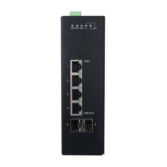
Page 13: Hardware Description
3. Hardware Description NGI-S04C2 Front Panel 4 10/100/1000Base-T ports + 2 100FX/Gigabit SFP slots Lite Managed Industrial Ethernet Switch 3.1. Connectors The Switch utilizes ports with copper and SFP fiber port connectors functioning under Ethernet/Fast Ethernet/Gigabit Ethernet standards. 10/100/1000Base-T Ports The 10/100/1000Base-T ports support network speeds of 10Mbps, 100Mbps or 1000Mbps, and can operate in half- and full-duplex transfer modes. -
Page 14: Installation
Step1: Unpack the device and other contents of the package. Step 2: Fasten DIN-Rail or Wall-mount kit on the rear of the NGI-S04C2 Step 3: Connect the 20~60V DC power supply to the PWR & RPS terminal block r on the top of the Switch (Refer to “Wiring Power Inputs”) - Page 15 Location: The NGI-S04C2 can be DIN-Rail-mounted in cabinet or enclosure. Mounting the Switch Place the NGI-S04C2 on the DIN rail from above using the slot and push the front of the switch toward the mounting surface until it snaps into place with a click sound.
- Page 16 The device is installed in a restricted-access location it has a separate protective earthing terminal on the chassis that must be permanently connected to earth ground to adequately ground the chassis and protect the operator from electrical hazards. Attention The product should be mounted in an Industrial Control Panel and the ambient temperature should not exceed 60°C (140°F).
- Page 17 Use copper conductors only, 60/75˚C (140/167°F), tighten to 0.56 N•m (5 lb•in). The wire gauge for the terminal block should range between 12~24 AWG. Redundant Power Input: Choose “Terminal Block (PWR)” as primary power. If you choose “Terminal Block (PWR)”, please refer to option 1, unless follow option 2. Option 1: Insert the terminal block connector which includes “PWR”...
- Page 18 If neither of these two conditions is satisfied, the Fault circuit will be closed. Warning Use copper conductors only, 60/75˚C (140/167°F), tighten to 0.56 N•m (5 lb•in). The wire gauge for the terminal block should range between 12~24 AWG.
-
Page 19: Led Indicators
3.3. LED Indicators This Switch is equipped with Unit LEDs to enable you to determine the status of the Switch, as well as Port LEDs to display what is happening in all your connections. They are as follows: Power on by terminal block PWR/4-pin mini DIN Illuminated connector at 20~60VDC. - Page 20 1. This device may not cause harmful interference. 2. This device must accept any interference received including interference that may cause undesired operation. ATTENTION If the equipment is used in a manner not specified by the Tripp Lite, the protection provided by the equipment may be impaired.
-
Page 21: Configuration
4. Configuration Initially, the new device connects the network using default IP (192.168.0.254). Access the IP address to enter the Wizard. After three seconds the “Welcome” screen will switch to the set-up screen as shown below. The following flow chart illustrates the installation and subsequent steps after plug in. - Page 22 Step 2: IP Address is to configure the management IP user can select DHCP mode or static mode to configure the switch IP as shown below. Step 3: Access Mode is to access the device have 2 options Security mode (HTTPs, SSH, and SNMPv3) and Normal mode (HTTP, TELNET, and SNMPv1/v2).
- Page 23 Default: Username: admin Password: admin After successful completion of the settings, the web-link will take you to the “Topology Map” as landing page shown below where you can access the Dashboard, Login, and Information.
-
Page 24: Dashboard Settings
4.1. Dashboard Settings The Dashboard is an intelligent system that provides real-time switch parameters that include performance, link status and data traffic information in an engaging, easy-view format for the end-users tricolor scheme as the Topology Map. The dashboard setting enables you to control the performance of the switch like CPU, Memory, Port Tx Usage, Port Rx Usage. - Page 25 Port Link Down Statistics User can select individual port or all ports information to reset to Port default on registration information. This field will download the statistics of port down information Download along with date time. Critical / Alert Threshold User can configure threshold value to normal, alert, critical CPU Usage percentage or disable the feature.
-
Page 26: Port Configuration
4.2. Port Configuration 4.2.1. Port Settings Introduction State In port configuration you can enable or disable the port. If the port is disabled the port remains off without any operation. To keep it operating, place the port in enable state. Speed It defines in which speed the port should operate. - Page 27 Auto-MDIX (automatic medium-dependent interface crossover) is a computer networking technology that automatically detects the required cable connection type (straight-through or crossover) and configures the connection appropriately, thereby removing the need for crossover cables to interconnect switches or connecting PCs peer-to-peer. When it is enabled, either type of cable can be used or the interface automatically corrects any incorrect cabling.
-
Page 28: Cli Configuration
4.2.1.1. CLI Configuration Node Command Description enable show interface IFNAME This command displays the current port configurations. configure interface IFNAME This command enters the interface configure node. interface show This command displays the current port configurations. interface loopback (none | mac) This command tests the loopback mode of operation for the specific port. -
Page 29: Web Configuration
L2SWITCH(config)#interface gi1/0/1 L2SWITCH(config-if)#speed auto 4.2.1.2. Web Configuration Parameter Description Port Settings Port Selects a port or a range of ports on which to configure the port. State Select option to enable / disable the port. Speed/duplex Select a speed/duplex for port(s). Flow Control User can configure flow control on interface on/off Click Apply to take effect the settings. -
Page 30: Loop Detection Configuration
4.2.2. Loop Detection Configuration Introduction Loop detection is designed to handle loop problems on the edge of your network. This can occur when a port is connected to a Switch that is in a loop state. Loop state occurs as a result of human error. -
Page 31: Cli Configuration
4.2.2.1. CLI Configuration Node Command Description enable show loop-detection This command displays the current loop detection configurations. configure loop-detection (disable | This command disables / enables the loop enable) detection on the switch. configure loop-detection address This command configures the destination MACADDR MAC for the loop detection special packets. -
Page 32: Web Configuration
4.2.2.2. Web Configuration Parameter Description State Select this option to enable loop guard on the Switch. Enter the destination MAC address the probe packets will be MAC Address sent to. If the port receives these same packets the port will be shut down. - Page 33 State This field displays if the loop guard feature is enabled. Status This field displays if the port is blocked. Loop Recovery This field displays if the loop recovery feature is enabled. Recovery This field displays the recovery time for the loop recovery Time (min) feature.
-
Page 34: Port Priority
4.2.3. Port Priority Introduction Typically, networks operate on a best-effort delivery basis, which means that all traffic has equal priority and an equal chance of being delivered in a timely manner. When congestion occurs, all traffic has an equal chance of being dropped. Using Port Priority feature, you can select specific network traffic, and prioritize it according to its relative importance. -
Page 35: Web Configuration
4.2.3.2. Web Configuration Parameter Description Port Priority Settings Selects a port or a range of ports on which to configure the Port priority. Select a priority for packets received by the port. Only packets Priority without 802.1p priority tagged will be applied the priority you set here. - Page 36 The Ethernet ring protection functionality includes the following: • Loop avoidance • The use of learning, forwarding, and Filtering Database (FDB) mechanisms Loop avoidance in an Ethernet ring is achieved by guaranteeing that, at any time, traffic may flow on all but one of the ring links. This particular link is called the ring protection link (RPL) and under normal conditions this ring link is blocked, i.e., not used for service traffic.
- Page 37 Wait to Block (WTB) timers -- This wait-to-block timer is activated on the RPL owner. The RPL owner uses WTB timers before initiating an RPL block and then reverting to the idle state after operator-initiated commands, such as for FS or MS conditions, are entered. Because multiple FS commands are allowed to co-exist in a ring, the WTB timer ensures that the clearing of a single FS command does not trigger the re-blocking of the RPL.
-
Page 38: Cli Configuration
you will get an error. If you still want to use this instance, you can change the Control VLAN to same as the control vlan of the instance first. And then configures the instance. 4.3.1.1. CLI Configuration Node Command Description enable show erps This command displays the ERPS... -
Page 39: Web Configuration
erps-ring version This command configures a version for the ERPS ring. erps-ring wtr-timer This command configures the WTR Timer for the ERPS ring. (default: 5 minutes) config-erps instance This command configures a new instance and -inst INSTANCE_ID specifies its control vlan and data vlan. control-vlan VLAN_ID data-vlan VLAN_ID... - Page 40 Revertive Enables / disables the revertive mode. Configures the instance for the ring. The Valid value is from 0 to 30. 0-Disable means the ERPS is running in version 1. The Instance control VLAN of the instance should be same as below Control VLAN.
-
Page 41: Web Configuration
Left Port Type The left port type. Right Port The right port. Right Port Type The right port type. WTB Timer The WTB time. Ring Status The current ring status. Left Port Status The current left port status. Right Port Status The current right port status. -
Page 42: Stp/Rstp
4.3.2. STP/RSTP Introduction (R)STP detects and breaks network loops and provides backup links between switches, bridges or routers. It allows a Switch to interact with other (R)STP compliant switches in your network to ensure that only one path exists between any two stations on the network. - Page 43 Forward Time (Forward Delay): This is the maximum time (in seconds) the Switch will wait before changing states. This delay is required because every switch must receive information about topology changes before it starts to forward frames. In addition, each port needs time to listen for conflicting information that would make it return to a blocking state;...
- Page 44 link fails, without the danger of bridge loops, or the need for manual enabling/disabling of these backup links. Bridge loops must be avoided because they result in flooding the network. The Spanning Tree Protocol (STP) is defined in the IEEE Standard 802.1D. As the name suggests, it creates a spanning tree within a mesh network of connected layer-2 bridges (typically Ethernet switches), and disables those links that are not part of the tree, leaving a single active path between any two network nodes.
- Page 45 automatically detect edge ports. As soon as the bridge detects a BPDU coming to an edge port, the port becomes a non-edge port. Forward Delay: The range is from 4 to 30 seconds. This is the maximum time (in seconds) the root device will wait before changing states (i.e., listening to learning to forwarding).
-
Page 46: Cli Configuration
Root Guard The Root Guard feature forces an interface to become a designated port to prevent surrounding switches from becoming a root switch. In other words, Root Guard provides a way to enforce the root bridge placement in the network. The Root Guard feature prevents a Designated Port from becoming a Root Port. - Page 47 counters all ports. enable clear spanning-tree This command clears spanning-tree statistics for a counters PORT_ID specific port. configure spanning-tree This command disables / enables the spanning tree (disable | enable) function for the system. configure spanning-tree This command configures the bridge times algorithm-timer (forward-delay,max-age,hello-time).
- Page 48 (disable|enable) interface spanning-tree cost This command configures the cost for the specific VALUE port. Cost range: 16-bit based value range 1-65535, 32-bit based value range 1-200000000. interface no spanning-tree cost This command configures the path cost to default for the specific port. interface spanning-tree This command configures the port priority for the...
-
Page 49: Web Configuration
4.3.2.2. Web Configuration Parameter Description Select Enabled to use Spanning Tree Protocol (STP) or Rapid State Spanning Tree Protocol (RSTP). Select to use either Spanning Tree Protocol (STP) or Rapid Mode Spanning Tree Protocol (RSTP). This is the maximum time (in seconds) the Switch will wait before changing states. -
Page 50: Web Configuration
Priority is used in determining the root switch, root port and designated port. The switch with the highest priority (lowest numeric value) becomes the STP root switch. If all switches have the same priority, the switch with the lowest MAC address will then become the root switch. - Page 51 Priority Configures the priority for the specific port. Configures the port type for the specific port. Edge or Edge Port Non-Edge. BPDU Filter Enables/Disables the BPDU filter function for the specific port. Enables/Disables the BPDU guard function for the specific BPDU Guard port.
-
Page 52: System Settings
4.4. System Settings 4.4.1. System Settings Host Name The hostname is same as the SNMP system name. Its length is up to 64 characters. Management VLAN The Management VLAN is used to configure the switch management VLAN. 4.4.1.1. CLI Configuration Node Command Description... -
Page 53: Igmp Snooping
4.4.2. IGMP Snooping Introduction The IGMP snooping is for multicast traffic. The Switch can passively snoop on IGMP packets transferred between IP multicast routers/switches and IP multicast hosts to learn the IP multicast group membership. It checks IGMP packets passing through it, picks out the group registration information, and configures multicasting accordingly. -
Page 54: Cli Configuration
4.4.2.1. CLI Configuration Node Command Description enable show igmp-snooping This command displays the current IGMP snooping configurations. enable show igmp-snooping This command displays the current IGMP counters snooping counters. enable show igmp-snooping This command displays the current IGMP querier Queriers. enable show multicast This command displays the multicast group in... -
Page 55: Ipv4 Settings
if-range This command disables the IGMP Snooping igmp-immediate-leave immediate leave function for the specific ports. if-range igmp-snooping This command configures the maximum group-limit VALUE groups for the specific ports. if-range no igmp-snooping This command removes the limitation of the group-limit maximum groups for the specific ports. - Page 56 configure configure terminal This command changes the mode to config mode. configure interface eth0 This command changes the mode to eth0 mode. eth0 show This command displays the eth0 configurations. eth0 ip address A.B.C.D/M This command configures a static IP and subnet mask for the system.
-
Page 57: Web Configuration
4.4.3.2. Web Configuration Parameter Description System Settings Enter up to 64 alphanumeric characters for the name of your Hostname Switch. The hostname should be the combination of the digit or the alphabet or hyphens (-) or underscores (_). Management VLAN This field is to configure Management VLAN . - Page 58 between 1 and 4094. Use a comma (,) or hyphen (-) to specify more than one VLANs. Select Delete and enter VLANs on which to have the Switch not perform IGMP snooping. Specify the action to perform when the Switch receives an Unknown Multicast unknown multicast frame.
-
Page 59: Network Topology
5. Network Topology 5.1. Map Settings Introduction The Topology Map is a feature to check neighbor devices’ information or to configure them easily. Click the Topology Map, the system will display topology as below. All devices connect to the Switch directly and support LLDP will be displayed on the screen. -
Page 60: Web Configuration
5.1.2. Web Configuration Background Settings You can upload your company floor layout plan picture in to the background image so that you can identify easily where the switch has been placed. Picture To choice a file which you want to display it in the background and the Preview window will display your select immediately. - Page 61 Color Allows the user to select standard color for the background. The Preview window will display your selection. Client Switch Management By right-clicking on the neighbor non-lite switch, this menu will appear and can configure as shown below.
- Page 62 Non-Lite Switch Menu: Save All Device Location To fix the location of all devices on the map, so that it restores its places after refresh. Login Web GUI To log in to the client device web GUI, and make necessary changes. By right-clicking on the neighbor lite switch, this menu will appear and you can configure as shown below.
-
Page 63: Neighbor Devises
5.2. Neighbor Devises 5.2.1. LLDP Introduction The Link Layer Discovery Protocol (LLDP) specified in this standard allows stations attached to an IEEE 802 LAN to advertise, to other stations attached to the same IEEE 802 LAN, the major capabilities provided by the system incorporating that station, the management address or addresses of the entity or entities that provide management of those capabilities, and the identification of the station’s point of attachment to the IEEE 802 LAN required by those management entity or entities. -
Page 64: Web Configuration
if-range lldp-agent This command configures the LLDP agent (disable|enable|rx-on function. ly|tx-only) disable – Disable the LLDP on the specific port. enable – Transmit and Receive the LLDP packet on the specific port. tx-only – Transmit the LLDP packet on the specific port only. -
Page 65: Manual Registration
Chassis ID The neighbor’s chassis ID. System Name The neighbor’s system name. System Description The neighbor’s system description. System Capabilities The neighbor’s capability. Management IP The neighbor’s management address. 5.2.2. Manual Registration Introduction If devices do not support LLDP and ONVIF, user has to enter the details of it by manually under manual registration. - Page 66 Parameter Description Manual Registration Settings User can select the type of the device for manual Type (ipcam|plc|switch|pc) registration like (ipcam|plc|switch|pc) connected as neighbor device to switch. The MAC address of the device selected for manual MAC Address registration. User can configure IP address of the manual registration device connected.
-
Page 67: Onvif
Switch. The Switch displays ONVIF devices up to total port count, NGI-S04C2 shows upto 10 ONVIF devices connected to it. If one or more ONVIF devices are connected to the same port it displays the last ONVIF device gets connect to 5.2.3.1. -
Page 68: Web Configuration
5.2.3.2. Web Configuration Parameter Description ONVIF Settings Select option to enable / disable the ONVIF feature on the State Switch. Configures the sending ONVIF discovery packet interval. Tx Interval Valid range is 6 ~ 3600 seconds. Apply Click Apply to take effect the settings. Refresh Click Refresh to begin configuring this screen afresh. -
Page 69: Topology Map
5.3. Topology Map The Topology Map is a feature to check neighbor devices’ information or to configure them easily. Click the Topology Map, the system will display topology as below. All devices connect to the Switch directly and support LLDP will be displayed on the screen. - Page 70 You can view the basic details of the devices connected to the host by placing the cursor on it. When there is something wrong with the device, the screen will appear as shown so that you can find the details of events that have gone wrong and correct them.
-
Page 71: Client Switch Management
5.3.1. Client Switch Management By right-clicking on the neighbor non-lite Switch, this menu will appear and you can configure as shown. Non-Lite Switch Menu: Save All Device Locations To fix the location of all devices on the map, so that it restores its places after refresh. -
Page 72: Quick Configuration Menu
5.3.2. Quick Configuration Menu By right-clicking on the neighbor lite management switch, this menu will appear and you can configure as shown. By right-clicking on the neighbor switch (only lite management switches), this menu will appear and you can configure as shown. -
Page 73: Ip Configuration
5.3.2.1. IP Configuration Parameter Description IPv4 Settings Configures the DHCP client function for your Switch. DHCP Client Enable means the Switch get an IP address from a DHCP server. Configures a static IPv4 address for your Switch in dotted IP Address decimal notation. -
Page 74: Loop Detection Configuration
5.3.2.2. Loop Detection Configuration Parameter Description Loop Detection Settings Select this option to enable / disable loop detection on the State Switch. Select a port or a range of ports which to configure loop Port detection. Select option to enable/disable the loop detection feature on State port(s). -
Page 75: Port Configuration
5.3.2.3. Port Configuration Parameter Description Port Settings Port Selects a port or a range of ports on which to configure the port. State Select option to enable / disable the port. Apply Click Apply to take effect the settings. Refresh Click Refresh to begin configuring this screen afresh. -
Page 76: Port Mirror Configuration
5.3.2.4. Port Mirror Configuration Parameter Description Port Mirror Settings Select option to enable / disable the port mirroring feature on the State Switch. Selects a port which packets received and transmitted by this Source Port port will be copied to the destination port. Destination Port Select a port which connects to a network traffic analyzer. -
Page 77: Storm Control Configuration
Parameter Description Port Priority Settings Selects a port or a range of ports on which to configure the Port priority. Priority Selects “Low”, “Medium” and “High” priority for the port(s). Click Apply to take effect the settings. Apply Refresh Click Refresh to begin configuring this screen afresh. Port Priority Status Port This field displays a port number. -
Page 78: Save Configuration
Refresh Click Refresh to begin configuring this screen afresh. Storm Control Status Port This field displays a port number. Multicast This field displays the multicast storm control state on the port. Broadcast This field displays the broadcast storm control state on the port. This field displays the DLF storm control state on the port. -
Page 79: Security
6. Security 6.1. 802.1x IEEE 802.1X is an IEEE Standard for port-based Network Access Control ("port" meaning a single point of attachment to the LAN infrastructure). It is part of the IEEE 802.1 group of networking protocols. It provides an authentication mechanism to devices wishing to attach to a LAN, either establishing a point-to-point connection or preventing it if authentication fails. - Page 80 When the client provides the login credentials, the Switch sends an authentication request to a RADIUS server. The RADIUS server validates whether this client is allowed access to the port. Local User Accounts By storing user profiles locally on the Switch, your Switch is able to authenticate users without interacting with a network authentication server.
-
Page 81: Cli Configuration
Quiet Period: Specify a period of the time the client has to wait before the next re-authentication attempt. This will prevent the Switch from becoming overloaded with continuous re-authentication attempts from the client. The acceptable range for this field is 0 to 65535 seconds. - Page 82 configure dot1x username This command configures the user account for <STRING> passwd local authentication. <STRING> configure no dot1x username This command deletes the user account for local <STRING> authentication. configure dot1x accounting This command enables/disables the dot1x local (disable|enable) accounting records. configure dot1x guest-vlan This command configures the guest vlan.
-
Page 83: Web Configuration
6.1.2. Web Configuration Parameter Description Select Enable to permit 802.1 x authentications on the Switch. State Note: You must first enable 802.1 x authentications on the Switch before configuring it on each port. Select whether to use Local or RADIUS as the authentication method. - Page 84 decimal notation. UDP Port The default port of a RADIUS server for authentication is 1812. Specify a password (up to 32 alphanumeric characters) as the key to be shared between the external RADIUS server and the Share Key Switch. This key is not sent over the network. This key must be the same on the external RADIUS server and the Switch.
-
Page 85: Web Configuration
6.1.3. Web Configuration Parameter Description Port Select a port number to configure. Select Enable to permit 802.1 x authentications on the port. 802.1x State You must first enable 802.1 x authentications on the Switch before configuring it on each port. Select Both to drop incoming and outgoing packets on the Admin Control port when a user has not passed 802.1x port authentication. - Page 86 Specify the amount of times the Switch will try to connect to Max-req Time the authentication server before determining the server is down. The acceptable range for this field is 1 to 10 times. Specify how often a client has to re-enter his or her username Reauth period and password to stay connected to the port.
-
Page 87: Acl
This field displays how often a client has to re-enter his or Reauth period her username and password to stay connected to the port. This field displays the period of the time the client has to wait Quiet period before the next re-authentication attempt. This field displays how long the Switch will wait before Supp timeout communicating with the server. - Page 88 DSCP value which will be override to all packets matched this profile. action 802.1p This command actives this profile and specify that remarking <0-7> it is for 802.1p remark. And configures the new 802.1p value which will be override to all packets matched this profile.
- Page 89 no l4-source-port This command removes the UDP/TCP source port IPADDR from the profile. L4-destination-port This command configures the UDP/TCP PORT destination port for the profile. no l4-destination-port This command removes the UDP/TCP destination port from the profile. vlan VLANID This command configures the VLAN for the profile.
-
Page 90: Web Configuration
6.2.2. Web Configuration Parameter Description Profile Name The access control profile name. State Selects Disables / Drop / Permits/ DSCP action for the profile. Configures the Ethernet type of the packets that you want to Ethernet Type filter. VLAN Configures the VLAN of the packets that you want to filter. Configures the source MAC of the packets that you want to Source MAC filter. -
Page 91: Port Security
Configures the bitmap mask of the source IP of the packets that you want to filter. Mask of Source IP If the Source IP field has been configured and this field is empty, it means the profile will filter the one IP configured in Source IP field. -
Page 92: Cli Configuration
Note: If you configure a port of the Switch from disabled to enabled, all of the MAC learned by this port will be clear. Default Settings The port security on the Switch is disabled. The Maximum MAC per port is 5. The port state of the port security is disabled. -
Page 93: Server Control
Parameter Description Port Security Settings Port Security Select Enable/Disable to permit Port Security on the Switch. Port Select a port number to configure. State Select Enable/Disable to permit Port Security on the port. The maximum number of MAC addresses allowed per Maximum MAC interface. -
Page 94: Web Configuration
6.4.2. Web Configuration Parameter Description Server Settings Selects Enable or Disable to enable or disable the HTTP HTTP Server State service. HTTPS Server Selects Enable or Disable to enable or disable the HTTPS State service. SNMPv1/v2c Selects Enable or Disable to enable or disable the SNMPv1/v2c Server State service. -
Page 95: Storm Control
HTTP Server Status Displays the current HTTP service status. HTTPS Server Displays the current HTTPS service status. Status SNMPv1/v2c Server Displays the current SNMPv1/v2c service status. Status SNMPv3 Server Displays the current SNMPv3 service status. Status SSH Server Status Displays the current SSH service status. Telnet Server Status Displays the current Telnet service status. -
Page 96: Storm Control
Selects a port or a range of ports on which to configure the alarm Port threshold. State Selects Enable / Disable the alarm threshold for the port(s). Packet Type Selects packet type one of Broadcast / Multicast / Broadcast and Multicast. -
Page 97: Web Configuration
L2SWITCH(config)#storm-control rate 1 type broadcast ports 1-6 L2SWITCH(config)#storm-control rate 1 type multicast ports 1-6 L2SWITCH(config)#storm-control rate 1 type DLF ports 1-6 6.5.2.2. Web Configuration Parameter Description Storm Control Settings Select individual port number or range for which you want to configure Port storm control settings. -
Page 98: Vlan
This field displays the DLF storm control state along with configured Rate(pps) rate of pps on the port. 6.6. VLAN 6.6.1. Port Isolation The port isolation is a port-based virtual LAN feature. It partitions the switching ports into virtual private domains designated on a per port basis. Data switching outside of the port’s private domain is not allowed. -
Page 99: Web Configuration
6.6.1.2. Web Configuration Parameter Description Select a port number to configure its port isolation settings. Port Select All Ports to configure the port isolation settings for all ports on the Switch. An egress port is an outgoing port, that is, a port through which a data packet leaves. -
Page 100: Vlan Settings
6.6.2. VLAN Settings 802.1Q VLAN A virtual LAN, commonly known as a VLAN, is a group of hosts with a common set of requirements that communicate as if they were attached to the Broadcast domain, regardless of their physical location. A VLAN has the same attributes as a physical LAN, but it allows for end stations to be grouped together even if they are not located on the same network switch. - Page 101 A broadcast frame (or a multicast frame for a multicast group that is known by the system) is duplicated only on ports that are members of the VID (except the ingress port itself), thus confining the broadcast to a specific domain. 802.1QPort Base VLAN ...
-
Page 102: Cli Configuration
Trunk port: Allows the user to configure up to 5 VLAN’s maximum on the interface and always tagged where its PVID is 1 (the system configures them automatically). The port should be connected to another switch. Default Settings All ports join in the VLAN 1. 6.6.2.1. - Page 103 interface acceptable frame type This command configures the acceptable frame (all|tagged|untagged) type. - acceptable all frame types. tagged - acceptable tagged frame only. untagged – acceptable untagged frame only. interface pvid VLANID This command configures a VLAN ID for the port default VLAN ID.
-
Page 104: Web Configuration
L2SWITCH(config-vlan-range)# fixed 1-5 L2SWITCH(config-vlan-range)# tagged 5 6.6.2.2. Web Configuration Parameter Description Select a port number to configure from the drop-down box. Port Select All to configure all ports at the same time. Role Select role on interface as access or trunk. User can configure maximum of 5 VLAN’s on each interface in VLAN the format 1,3,7,10,25. -
Page 105: Diagnosis
7. Diagnosis 7.1. Alarm Information The feature displays if there are any abnormal situation need process immediately. Notice: The Alarm DIP Switch allow users to configure if send alarm message when the corresponding event occurs. For Example: PWR: ON, The Switch will send alarm message when the main power supply disconnect. RPS: ON, The Switch will send alarm message when the redundant power supply disconnect. -
Page 106: Port Mirror
The field display the current Redundant Power Supply Control DIP settings. Disable – RPS Control controlled by user configurations. Enable – RPS control is enabled. Refresh Button will refresh the page to display the applied Refresh changes 7.2. Port Mirror The Port-Based Mirroring is used on a network switch to send a copy of network packets sent/received on one switch ports to a network monitoring connection on another switch port (Destination Port). -
Page 107: Web Configuration
7.2.2. Web Configuration Parameter Description Port Mirror Settings Select option to enable / disable the port mirroring feature on State the Switch globally. Monitor to Port Select the port which connects to a network traffic analyzer. Settings in this field apply to all ports. Use this field only if you want to make some settings the same All Ports for all ports. -
Page 108: Port Statistics
7.3. Port Statistics This feature helps users to monitor the ports’ statistics, to display the link up ports’ traffic utilization only. 7.3.1. CLI Configuration Node Command Description enable show port-statistics This command displays the link up ports’ statistics. Example : L2SWITCH#show port-statistics Packets Bytes... -
Page 109: Tilization
7.4. Port Utilization This feature helps users to monitor the ports’ traffic utilization, to display the link up ports’ traffic utilization only. 7.4.1. CLI Configuration Node Command Description enable show port-utilization This command displays the link up ports’ traffic utilization. Example: L2SWITCH#show port-utilization Port Speed Utilization(%) -
Page 110: Syslog
7.5. Syslog The syslog function records some of system information for debugging purpose. Each log message recorded with one of these levels, Alert / Critical / Error / Warning / Notice / Information. The syslog function can be enabled or disabled. The default setting is disabled. -
Page 111: Web Configuration
7.5.2. Web Configuration Parameter Description Enter the Syslog server IP address. Server IP Select Enable to activate switch sent log message to Syslog server when any new log message occurred. Click Apply to add/modify the settings. Apply Click Refresh to begin configuring this screen afresh. Refresh Alert/Critical/Error/Warning/Notice/Information Select... -
Page 112: Utilization Threshold
7.6. Utilization Threshold This feature alerts the user when the packet rate in the particular port is above the required rate. 7.6.1. CLI Configuration Node Command Description configure port-utilization The command disables / enables the port threshold utilization threshold function globally. (disable|enable) configure interface IFNAME... -
Page 113: Web Configuration
7.6.2. Web Configuration Parameter Description Alarm Threshold Settings Select option to enable / disable the alarm threshold feature on State the Switch. Selects a port or a range of ports on which to configure the Port alarm threshold. State Selects Enable / Disable the alarm threshold for the port(s). Configures the threshold rate. -
Page 114: Management
Packet Rate This field displays the current threshold. 8. Management 8.1. SNMPv1/v2c Simple Network Management Protocol Simple Network Management Protocol (SNMP) is used in network management systems to monitor network-attached devices for conditions that warrant administrative attention. SNMP is a component of the Internet Protocol Suite as defined by the Internet Engineering Task Force (IETF). -
Page 115: Web Configuration
8.1.1.2. Web Configuration Parameter Description SNMP Settings SNMP State Select option to enable / disable the SNMP on the Switch. System Name User can configure system name. System Location User can configure the switch deployed location for reference. User can configure System Contact person information like System Contact name or number. -
Page 116: Web Configuration
Example: L2SWITCH#configure terminal L2SWITCH(config)#snmp community public rw trusted-host 192.168.200.106/24 8.1.2.2. Web Configuration Parameter Description Community Name Enter a Community string; this will act as a password for requests from the management station. An SNMP community string is a text string that acts as a password. -
Page 117: Snmp Event Settings
Community Name List This field displays the index number of an entry. Community String This field displays the community string of an entry. Rights This field displays the right of an entry. Network ID of This field displays the network ID of trusted host of an entry. Trusted Host Number of Mask This field displays the length of the subnet mask bits of an... -
Page 118: Web Configuration
(disable/enable) configure snmp trap-event This command enables/disables the stp-topology-change stp-topology-change trap. (disable/enable) configure snmp trap-event This command enables/disables traffic-monitor thetraffic-monitor trap. (disable/enable) 8.1.3.2. Web Configuration The features allow users to enable/disables individual trap notification. Alarm-Over-Heat - Trap when system’s temperature is too high. Alarm-Over-Load - Trap when system is over load. -
Page 119: Port Trap Event Settings
Apply Click Apply to configure the settings. Refresh Click Refresh to begin configuring this screen afresh. 8.1.4. Port Trap Event Settings The features allow users to enable/disables port-link-change trap notification by individual port. 8.1.4.1. CLI Configuration Node Command Description enable show snmp port-link-change-trap This command displays the SNMP port link-change trap configurations. -
Page 120: Snmp Trap Receiver Settings
Port Selects the range of ports. State User can enable /disable trap events when port link change. Apply Click Apply to configure the settings. Refresh Click Refresh to begin configuring this screen afresh. 8.1.5. SNMP Trap Receiver Settings The features allow users to configure trap receiver configuration. 8.1.5.1. -
Page 121: Snmp 3
This field displays the index number of the trap receiver entry. Click the number to modify the entry. IP Address This field displays the IP address of the remote trap station. This field displays the version of Simple Network Management Version Protocol in use. -
Page 122: Web Configuration
8.2.1.2. Web Configuration Parameter Description Group Settings Group Name Enter the v3 user name. Security Level Select the security level of the v3 group to use. Note that if a group is defined without a read view than all Read View objects are available to read. -
Page 123: User
Write View Notify View Click Delete to remove a v3 group. Action 8.2.2. SNMPv3 User 8.2.2.1. CLI Configuration Node Command Description enable show snmp user This command displays all snmp v3 user. enable configure terminal This command changes the node to configure node. -
Page 124: Web Configuration
8.2.2.2. Web Configuration Parameter Description User Settings User Name Enter the v3 user name. Group Name Map the v3 user name into a group name. Select the security level of the v3 user to use. noauth means no authentication and no encryption. Security Level auth means messages are authenticated but not encrypted. -
Page 125: View
Refresh Click Refresh to begin configuring this screen afresh. User Status User Name This field displays the v3 user name. Group Name This field displays the group name which the v3 user mapping. Auth Protocol These fields display the security level to this v3 user. Priv Protocol Rowstatus This field displays the v3 user row status. -
Page 126: Web Configuration
8.2.3.2. Web Configuration Parameter Description View Settings Enter the v3 view name for creating an entry in the SNMPv3 View Name MIB view table. The OID defining the root of the subtree to add to (or exclude View Subtree from) the named view. Select included or excluded to define subtree adding to the View Type view or not. -
Page 127: Cli Configuration
NTP provides Coordinated Universal Time (UTC). No information about time zones or daylight saving time is transmitted; this information is outside its scope and must be obtained separately. UDP Port: 123. Daylight saving is a period from late spring to early fall when many countries set their clocks ahead of normal local time by one hour to give more daytime light in the evening. - Page 128 min: 0-59 sec: 0-59 Note: If you configure Daylight Saving Time after you configure the time, the Switch will apply Daylight Saving Time. configure time date Sets the current date on the Switch. YEAR/MONTH/DAY year: 1970- month: 1-12 day: 1-31 configure time daylight-saving-time This command enables the daylight saving time.
-
Page 129: Web Configuration
8.3.2. Web Configuration Parameter Description Current Time and Date Current Time This field displays the time you open / refresh this menu. Current Date This field displays the date you open / refresh this menu. Time and Date Setting Select this option if you want to enter the system date and time Manual manually. - Page 130 for the timeserver for up to 60 seconds. Select the time difference between UTC (Universal Time Time Zone Coordinated, formerly known as GMT, Greenwich Mean Time) and your time zone. Daylight Saving Settings Select Enable if you want to use Daylight Saving Time. State Otherwise, select Disable to turn it off.
-
Page 131: Cli Configuration
because Germany's time zone is one hour ahead of GMT or UTC (GMT+1). Apply Click this button to take effect the settings. Refresh Click this button to reset the fields to the last setting. 8.4. System Information The System Information window appears each time you log into the program. Alternatively, this window can be accessed by clicking System Information. -
Page 132: System Maintenance
Host name This field displays the host name of the Switch. Boot Code Version This field displays the boot code version. Firmware Version This field displays the firmware version. Built Date This field displays the built date of the firmware. This field displays whether the DHCP client is enabled on the DHCP Client Switch. -
Page 133: Web Configuration
8.5.1.2. Web Configuration Click the “Choose File” button to select the new configuration file which you want to upgrade it to the Switch. Click the “Upload” button to start the upgrade procedures. Click the “Download” button to download the current configurations to local host. Reset Configuration Click the “Reset”... -
Page 134: Web Configuration
8.5.2.2. Web Configuration Click the “Choose File” button to select the new firmware which you want to upgrade it to the Switch. Click the “Upgrade” button to start the upgrade procedures. 8.5.3. Reboot 8.5.3.1. CLI Configuration Node Command Description configure reboot This command reboots the system. -
Page 135: Cli Configuration
MAC. Users can use the new user account to enter the Switch and then create a new user account. Default Settings Maximum user account : 6. Maximum user name length : 32. Maximum password length : 32. Default user account for privileged mode : admin / admin. - Page 136 User Account Settings User Name Type a new username or modify an existing one. Type a new password or modify an existing one. Enter up to 32 User Password alphanumeric or digit characters. Select with which group the user associates. admin (read and User Authority write) or normal (read only) for this user account Dot1x user for radius.
-
Page 137: Warranty & Product Registration
TRIPP LITE warrants its products to be free from defects in materials and workmanship for a period of three (3) years from the date of initial purchase. TRIPP LITE’s obligation under this warranty is limited to repairing or replacing (at its sole option) any such defective products. - Page 138 The user must use shielded cables and connectors with this equipment. Any changes or modifications to this equipment not expressly approved by Tripp Lite could void the user’s authority to operate this equipment.