Table of Contents
Advertisement
Quick Links
COPYRIGHT
All rights reserved. No part of this publication may be reproduced, stored in a retrieval
system, or transmitted in any form or by any means, whether electronic, mechanical,
photo copying, recording or otherwise, without the prior written permission of the
publisher.
FCC WARNING
This equipment has been tested and found to comply with the limits for a class
A device, pursuant to part 15 of FCC rules. These limits are designed to provide
reasonable protection against harmful interference in a commercial installation.
This equipment generates uses and can radiate radio frequency energy and, if not
installed and used in accordance with the instructions, may cause harmful interference
to radio communication. Operation of this equipment in a residential area is likely to
cause harmful interference, in which case, the user will be required to correct the
interference at the user's own expense.
CE
This is a Class A product. In a domestic environment, this product may cause
radio interference in which case the user may be required to take adequate
measures.
HOT & COLD WARNING
The Switch surface will be getting very hot or cold depend on the operating
environment. Please take special care when touch to the working switch.
1
Advertisement
Table of Contents

Related Manuals for Tripp Lite NGI-M05-C1


Summary of Contents for Tripp Lite NGI-M05-C1
- Page 1 COPYRIGHT All rights reserved. No part of this publication may be reproduced, stored in a retrieval system, or transmitted in any form or by any means, whether electronic, mechanical, photo copying, recording or otherwise, without the prior written permission of the publisher.
- Page 2 Take special care to read and understand all the content in the warning boxes. Warning Do not work on the system or connect or disconnect cables during periods of lightning activity. Warning Before working on equipment that is connected to power lines, remove jewelry (including rings, necklaces and watches).
- Page 3 Read the wall-mounting instructions carefully before beginning installation. Failure to use the correct hardware or to follow the correct Warning procedures could result in a hazardous situation to people and damage to the system. Before performing any of the following procedures, ensure that power is removed from the DC circuit.
- Page 4 When installing or replacing the unit, the ground connection must always be made first and disconnected last. Warning Voltages that present a shock hazard may exist on Power over Ethernet (PoE) circuits if interconnections are made using Warning uninsulated exposed metal contacts, conductors or terminals. Avoid using such interconnection methods, unless the exposed metal parts are located within a restricted access location and users and service people who are authorized within the restricted access location are...
-
Page 5: Table Of Contents
1. ABOUT THIS MANUAL................12 1.1...................... 12 NTRODUCTION 1.2....................... 12 URPOSE 1.3...................... 12 ERMS SAGE 2. ABOUT THE NGI-M05-C1 ................13 2.1......................13 EATURES 2.2....................13 PECIFICATIONS 3. HARDWARE DESCRIPTION ............... 15 3.1......................15 ONNECTORS 3.2. - Page 6 5.2.1.1. CLI C ....................42 ONFIGURATION 5.2.1.2....................42 ONFIGURATION 5.2.2. MAC T ........................44 ABLE 5.2.2.1. CLI C ....................44 ONFIGURATION 5.2.2.2....................44 ONFIGURATION 5.2.3........................46 5.2.3.1. CLI C ....................46 ONFIGURATION 5.2.3.2....................46 ONFIGURATION 5.3.......................
- Page 7 6.2.1.3.1. CLI C ....................83 ONFIGURATION 6.2.1.3.2. W ....................84 ONFIGURATION 6.2.2. IGMP S ..................85 NOOPING ILTERING 6.2.2.1....................... 85 ENERAL ETTINGS 6.2.2.1.1. CLI C ....................85 ONFIGURATION 6.2.2.1.2. W ....................85 ONFIGURATION 6.2.2.2...................... 87 ULTICAST ROUP 6.2.2.2.1. CLI C ....................
- Page 8 6.8. ERPS ......................... 128 6.8.1......................130 ETTINGS 6.8.1.1. CLI C ....................130 ONFIGURATIONS 6.8.1.2....................131 ONFIGURATIONS 6.8.2........................133 NSTANCE 6.8.2.1. CLI C ....................133 ONFIGURATIONS 6.8.2.2....................134 ONFIGURATIONS 6.9.................... 135 GGREGATION 6.9.1......................135 TATIC RUNK 6.9.1.1.
- Page 9 7.1.2.2......................175 INDING ABLE 7.1.2.2.1. CLI C ....................175 ONFIGURATIONS 7.1.2.2.2. W ....................175 ONFIGURATIONS 7.1.3. ARP I ......................176 NSPECTION 7.1.3.1. ARP I ......................177 NSPECTION 7.1.3.1.1. CLI C ....................177 ONFIGURATIONS 7.1.3.1.2. W ....................178 ONFIGURATIONS 7.1.3.2......................
- Page 10 9.1.1.1.2. W ....................209 ONFIGURATIONS 9.1.1.2...................... 210 OMMUNITY 9.1.1.2.1. CLI C ....................210 ONFIGURATIONS 9.1.1.2.2. W ....................211 ONFIGURATIONS 9.1.2. SNMP T ........................ 213 9.1.2.1....................213 ECEIVER ETTINGS 9.1.2.1.1. CLI C ....................213 ONFIGURATIONS 9.1.2.1.2. W ....................213 ONFIGURATIONS 9.1.2.2.
- Page 11 9.7.1.1. CLI C ....................240 ONFIGURATION 9.7.1.2....................241 ONFIGURATION 9.7.2..................... 243 ANUAL EGISTRATION 9.7.2.1. CLI C ....................243 ONFIGURATIONS 9.7.2.2....................243 ONFIGURATIONS 9.7.3. ONVIF ........................245 9.7.3.1. CLI C ....................245 ONFIGURATIONS 9.7.3.2....................245 ONFIGURATIONS 9.8....................
-
Page 12: About This Manual
This guide describes how to install and configure the NGI-M05-C1 Industrial Managed Switch. 1.3. Terms/ Usage In this manual, the term “Switch” (first letter upper case) refers to the NGI-M05-C1 Switch, and “switch” (first letter lower case) refers to other switches. -
Page 13: About The Ngi-M05-C1
2. About the NGI-M05-C1 2.1. Features Network Functions Traffic Management & QoS Port-based Mirroring Port Priority 256 Active VLAN Rate Limitation IGMP Snooping v1/v2/v3 Storm Control IGMP Querier Port Isolation DHCP Relay/Option 82 802.1Q Tag-based VLAN Link Aggregation Auto MDI/MDI-X... - Page 14 Performance Switching fabric 12 Gbps L2 forwarding 8.92 Mpps Packet buffer size 4.1Mbits MAC entries 08 K Jumbo frame 10 K Throughput 1,488,000pps when 1000Mbps speed Physical ports 10/100/1000Base-T (RJ45) Gigabit SFP slots Power Input Voltage: Primary inputs 20~57VDC at a maximum of 1.5A Redundant inputs 20~57VDC at a maximum of 1.5A Connection:...
-
Page 15: Hardware Description
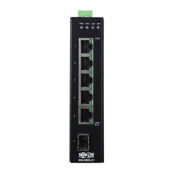
3. Hardware Description NGI-M05-C1 Front Panel 5 10/100/1000Base-T ports & 1 Gigabit SFP slots Managed Industrial Ethernet Switch 3.1. Connectors The Switch utilizes ports with copper and SFP fiber port connectors functioning under Ethernet/Fast Ethernet/Gigabit Ethernet standards. 10/100/1000Base-T Ports The 10/100/1000Base-T ports support network speeds of 10Mbps, 100Mbps or 1000Mbps, and can operate in half- and full-duplex transfer modes. -
Page 16: Nstallation
The NGI-M05-C1 Series is an open type device and NGI-M05-C1 Series shall be DIN-Rail mounted or wall mounted (optional) in cabinet or enclosure. Hardware Installation Step 1: Unpack the device and other contents of the package. Step 2: Fasten DIN-Rail or Wall-mount kit on the rear of the NGI-M05-C1. - Page 17 Location: The NGI-M05-C1 can be DIN-Rail-mounted in cabinet or enclosure. Mounting the Switch Place the NGI-M05-C1 on the DIN rail from above using the slot. Push the front of the switch toward the mounting surface until it snaps into place with a click sound.
- Page 18 Dismounting the Switch Pull out the lower edge of the switch and then remove the switch from the DIN rail. Ground the Switch: Before powering on the switch, ground the switch to earth. Ensure the rack on which the switch is to be mounted is properly grounded and incompliance with ETSI ETS 300 253.
- Page 19 Step 2: Use your finger to press the green plug on top of terminal block connector to insert power cables. Step 3: Insert the terminal block connector which includes “PWR” and “RPS” into the terminal block receptor which is located on the top panel. Option 2: Insert the “DC-Jack”...
- Page 20 Wiring the Alarm Contact: The Alarm Contact consists of the two last contacts of the terminal block on switch’s top panel. ALM: The two last contacts of the 6-contact terminal block connector are used to detect both power faults and port faults. The two wires attached to the ALM contacts form an open circuit when: 1.
-
Page 21: Led Indicators
3.3. LED Indicators This Switch is equipped with Unit LEDs to enable you to determine the status of the Switch, as well as Port LEDs to display what is happening in all your connections. They are as follows: Illuminated Power On by terminal block PWR or DC-Jack (Green) Terminal block PWR/DC-Jack fails or is not available Illuminated... - Page 22 OFF: Primary power alarm reporting is disabled ON: Redundant power alarm reporting is enabled OFF: Redundant power alarm reporting is disabled...
-
Page 23: System Status
4. System Status 4.1. Console Port Connect your computer to the console port on the Switch using the appropriate cable. Use terminal emulation software with the following settings: Default Settings for the Console Port Setting Default Value Terminal Emulation VT100 Baud Rate 38400... -
Page 24: Cli Command Concept
You can execute a few limited commands when CLI prompt is displayed as below. L2SWITCH> If you want to execute more powerful commands, you must enter the privileged mode. Input command “enable” L2SWITCH>enable Input a valid username and password when below prompt are displayed. user: admin password: admin L2SWITCH#... - Page 25 interface Its command prompt is “L2SWITCH(config-if)#”. It means these commands can be executed in this command prompt. In Configure code, executing command “interface gigaethernet1/0/5” enter the interface port 5 node. In Configure code, executing command “interface fastethernet1/0/5” enter the interface port 5 node.
-
Page 26: Anagement Via Nternet Rowser Nterface
4.5. Management via Internet Browser Interface From a PC, open your Web browser, type the following in the Web address (or location) box: http://192.168.0.254 and then press <Enter>. This is the factory default IP address for the Switch. A login dialog is displayed, as shown in the figure: Parameter Description... -
Page 27: Ystem Nformation
4.6. System Information 4.6.1. CLI Configuration Node Command Description enable show hostname This command displays the system’s network name. enable show interface eth0 This command will display the interface et0 information. enable show model This command will display information of switch like vendor, product, mac-address, serial boot code, firmware version etc…... -
Page 28: Web Configuration
4.6.2. Web Configuration The System Information window appears each time you log into the program. Alternatively, this window can be accessed by clicking System Status > System Information Parameter Description System Information Model Name This field displays the model name of the Switch. Host name This field displays the name of the Switch. - Page 29 Default Gateway This field indicates the default gateway of the Switch. This field displays the MAC (Media Access Control) address MAC Address of the Switch. The serial number assigned by manufacture for identification Serial Number of the unit. This field displays the VLAN ID that is used for the Switch Management VLAN management purposes.
-
Page 30: Basic Settings
5. Basic Settings 5.1. System Settings 5.1.1. System Management VLAN To specify a VLAN group which can access the Switch. The valid VLAN range is from 1 to 4094. If you want to configure a management VLAN, the management VLAN should ... - Page 31 enable & renew: Use DHCP client to get an IP address from DHCP server. next_restart: The settings will take effect on next system restart. eth0 management vlan <1-4094> This command configures the management vlan. eth0 ip ipv6-address This command configures a global AAAA:BBBB:CCCC:DDDD:E scope of IPv6 address and subnet mask EEE:FFFF:GGGG:HHHH/M...
-
Page 32: Web Configuration
5.1.1.2. Web Configuration Parameter Description System Settings Hostname The field configures a hostname for the system. Management VLAN The field configures a VLAN group to manage the Switch. IPv4 Settings Select Enable to allow the Switch to automatically get an IP address from a DHCP server. - Page 33 Select Enable to allow the Switch to automatically get an IP address from a DHCPv6 server. Click Renew to have the DHCPv6 Client Switch re-get an IP address from the DHCP server. Select Disable if you want to configure the Switch’s IP address manually.
-
Page 34: Jumboframe
5.1.2. Jumbo Frame Jumbo frames are Ethernet frames with a payload greater than 1500 bytes. Jumbo frames can enhance data transmission efficiency in a network. The bigger the frame size, the better the performance. Notice: The default jumbo frame is 10240 bytes. ... -
Page 35: Sntp
5.1.3. SNTP The Network Time Protocol (NTP) is a protocol for synchronizing the clocks of computer systems over packet-switched, variable-latency data networks. A less complex implementation of NTP, using the same protocol but without requiring the storage of state over extended periods of time is known as the Simple Network Time Protocol (SNTP).NTP provides Coordinated Universal Time (UTC). - Page 36 day: 1-31 configure time daylight-saving-time This command enables the daylight saving time. configure no time daylight-saving-time This command disables daylight saving on the Switch. configure time daylight-saving-time start- This command sets the start time of date the Daylight Saving Time. (first|second|third|fourth|last)(S unday|Monday|Tuesday|Wedne sday|Thursday|Friday|Saturday...
-
Page 37: Web Configuration
5.1.3.2. Web Configuration Parameter Description Current Time and Date Current Time This field displays the time you open / refresh this menu. Current Date This field displays the date you open / refresh this menu. Time and Date Setting Select this option if you want to enter the system date and time Manual manually. - Page 38 server. The Switch searches for the timeserver for up to 60 seconds. Select the time difference between UTC (Universal Time Time Zone Coordinated, formerly known as GMT, Greenwich Mean Time) and your time zone from the drop-down list box. Daylight Saving Settings Select Enable if you want to use Daylight Saving Time.
-
Page 39: Management Host
5.1.4. Management Host The feature limits the hosts which can manage the Switch. The default has no management host. That is, any hosts can manage the Switch via telnet or web browser. If user has configured one or more management host, the Switch can be managed by these hosts only. -
Page 40: Web Configuration
Link encap:Ethernet HWaddr 00:0B:04:90:60:21 inet addr:192.168.202.74 Bcast:192.168.202.255 Mask:255.255.255.0 inet6 addr: fe80::20b:4ff:fe90:6021/64 Scope:Link UP BROADCAST RUNNING ALLMULTI MULTICAST MTU:1500 Metric:1 ASYMMTU:0 RX packets:17931 errors:0 dropped:6680 overruns:0 frame:0 TX packets:6500 errors:0 dropped:0 overruns:0 carrier:0 collisions:0 txqueuelen:500 RX bytes:3565872 (3.4 Mb) TX bytes:1173040 (1.1 Mb) 5.1.4.2. -
Page 41: Mac Management
5.2. MAC Management Dynamic Address The MAC addresses are learnt by the switch. When the switch receives frames, it will record the source MAC, the received port and the VLAN in the address table with an age time. When the age time is expired, the address entry will be removed from the address table. -
Page 42: Static Mac
Figure: MAC Table Flowchart Notices: The default MAC address table age time is 300 seconds. The Maximum static address entry is 256. 5.2.1. Static MAC A static Media Access Control (MAC) address is an address that has been manually entered in the MAC address table, and do not age out. - Page 43 Static MAC Settings Enter the MAC address of a computer or device that you want MAC Address to add to the MAC address table. Valid format is hh:hh:hh:hh:hh:hh. VLAN ID Enter the VLAN ID to apply to the computer or device. Enter the port number to which the computer or device is Port connected.
-
Page 44: Mac Table
5.2.2. MAC Table 5.2.2.1. CLI Configuration Node Command Description enable show mac-address-table This command displays the current (static|dynamic) static/dynamic unicast address entries. enable show mac-address-table This command displays information of a mac MACADDR specific MAC. enable show mac-address-table This command displays the current unicast port PORT_ID address entries learnt by the specific port. - Page 45 VLAN ID This field displays the VLAN ID of the MAC address entry. This field displays the port number / Trunk ID the MAC address entry is associated. Port / Trunk ID It displays CPU if it is the entry for the Switch itself. The CPU means that it is the Switch’s MAC.
-
Page 46: Age Time
5.2.3. Age Time 5.2.3.1. CLI Configuration Node Command Description enable show mac-address-table This command displays the current MAC aging-time address table age time. enable configure terminal This command changes the node to configure node. configure mac-address-table aging- This command configures the mac table aging time VALUE time. -
Page 47: Port Mirror
5.3. Port Mirror Port-Based Mirroring The Port-Based Mirroring is used on a network switch to send a copy of network packets sent/received on one or a range of switch ports to a network monitoring connection on another switch port (Monitor to Port). This is commonly used for network appliances that require monitoring of network traffic, such as an intrusion-detection system. -
Page 48: Web Configuration
L2SWITCH(config)#exit L2SWITCH#show mirror Mirror Configurations: State : Disabled. Monitor port : 9. Ingress port(s): 1-8. Egress port(s) : None. 5.3.2. Web Configuration Parameter Description Port Mirroring Settings Select Enable to turn on port mirroring or select Disable to State turn it off. Monitor to Port Select the port which connects to a network traffic analyzer. - Page 49 Refresh Click Refresh to begin configuring this screen afresh.
-
Page 50: Port Settings
5.4. Port Settings Duplex Mode A duplex communication system is a system composed of two connected parties or devices that can communicate with one another in both directions. Half Duplex: A half-duplex system provides for communication in both directions, but only one direction at a time (not simultaneously). -
Page 51: General Settings
Auto Negotiation Auto (auto-negotiation) allows one port to negotiate with a peer port automatically to obtain the connection speed and duplex mode that both ends support. When auto- negotiation is turned on, a port on the Switch negotiates with the peer automatically to determine the connection speed and duplex mode. - Page 52 100-full–n | 100-half | 100-half- auto: Auto negotiation mode. n | 1000-full | 1000-full-n) 10-full: 10Mbps Full duplex force mode. 10-full-n: 10Mbps Full duplex auto negotiation mode. 10-half: 10Mbps Half duplex force mode. 10-half-n: 10Mbps Half duplex auto negotiation mode. 100-full: 100Mbps Full duplex force mode.
- Page 53 1000-full:1000Mbps Full duplex force mode. 1000-full-n: 1000Mbps Full duplex auto negotiation mode.
-
Page 54: Web Configuration
5.4.1.2. Web Configuration Parameter Description Port Settings Port Select a port or a range ports you want to configure on this screen. State Select Enable to activate the port or Disable to deactivate the port. Select the speed and duplex mode of the port. The choices are: •... -
Page 55: Cli Configuration
Port Status Port This field displays the port number. State This field displays whether the port is enabled or disabled. This field displays the speed either 10M, 100M or 1000M and the Speed/Duplex duplex mode Full or Half. Flow Control This field displays whether the port’s flow control is On or Off. -
Page 56: Web Configuration
if-range alias STRING This command configures an alias for the specific ports. The length of alias is up to 64 characters. if-range no alias This command reset the alias to default. 5.4.2.2. Web Configuration Parameter Description Port Settings Select a port or a range ports you want to configure on this Port screen. - Page 57 The field displays the detail port status if the port is blocked by Status some protocol. Uptime The sustained time from last link up. Medium Mode The current working medium mode, copper or fiber, for the port.
-
Page 58: Advanced Settings
6. Advanced Settings 6.1. Bandwidth Control 6.1.1. Each egress port can support up to 8 transmit queues. Each egress transmit queue contains a list specifying the packet transmission order. Every incoming frame is forwarded to one of the 8 egress transmit queues of the assigned egress port, based on its priority. The egress port transmits packets from each of the 8 transmit queues according to a configurable scheduling algorithm, which can be a combination of Strict Priority (SP) and/or Weighted Round Robin (WRR). - Page 59 Port Based QoS - Assign priority to packets based on the incoming port on the Switch. DSCP Based QoS - Assign priority to packets based on their Differentiated Services Code Points (DSCPs). Note: Advanced QoS methods only affect the internal priority queue mapping for the Switch.
- Page 60 be used as VLAN identifiers, allowing up to 4094 VLANs. On bridges, VLAN 1 is often reserved for management. Priority Levels PCP: Priority Code Point. Network Priority Traffic Characteristics 0 (lowest) Background Best Effort Excellent Effort Critical Applications Video, <100ms latency Video, <...
-
Page 61: Port Priority
6.1.1.1. Port Priority 6.1.1.1.1. CLI Configuration Node Command Description enable show interface This command displays the current port IFNAME configurations. enable configure terminal This command changes the node to configure node. configure interface IFNAME This command enters the interface configure node. - Page 62 Apply Click Apply to take effect the settings. Refresh Click Refresh to begin configuring this screen afresh.
-
Page 63: Ip Diffserv (Dscp)
6.1.1.2. IP DiffServ (DSCP) DiffServ (DSCP) Differentiated Services or DiffServ is a computer networking architecture that specifies a simple, scalable and coarse-grained mechanism for classifying, managing network traffic and providing Quality of Service (QoS) guarantees on modern IP networks. DiffServ can, for example, be used to provide low-latency, guaranteed service (GS) to critical network traffic such as voice or video while providing simple best-effort traffic guarantees to non- critical services such as web traffic or file transfers. -
Page 64: Cli Configuration
Precedence 111 - Network Control 110 - Internetwork Control 101 - CRITIC/ECP 100 - Flash Override 011 - Flash 010 - Immediate 001 - Priority 000 - Routine The use of the Delay, Throughput, and Reliability indications may increase the cost (in some sense) of the service. -
Page 65: Web Configuration
6.1.1.2.2. Web Configuration Parameter Description DSCP Settings “Tag Over DSCP” or “DSCP Over Tag”. “Tag Over DSCP” means the Mode 802.1p tag has higher priority than DSCP. This field displays each priority level. The values range from 0 (lowest Priority priority) to 7 (highest priority). -
Page 66: Priority/Queue Mapping
6.1.1.3. Priority/Queue Mapping 6.1.1.3.1. CLI Configuration Node Command Description enable show queue cos-map This command displays the current 802.1p priority mapping to the service queue. enable configure terminal This command changes the node to configure node. configure queue cos-map <0-7> This command configures the 802.1p priority <0-7>... -
Page 67: Web Configuration
6.1.1.3.2. Web Configuration Parameter Description Priority/Queue Mapping Settings Click this button to reset the priority to queue mappings to the Reset to Default defaults. This field displays each priority level. The values range from 0 Priority (lowest priority) to 7 (highest priority). Queue ID Select the number of a queue for packets with the priority level. -
Page 68: Schedule Mode
6.1.1.4. Schedule Mode Queuing Algorithms Queuing algorithms allow switches to maintain separate queues for packets from each individual source or flow and prevent a source from monopolizing the bandwidth. Strict-Priority (SPQ) The packets on the high priority queue are always service firstly. Weighted round robin (WRR) ... -
Page 69: Web Configuration
configure qos mode wrr-queue This command configures the QoS scheduling weights <1-127> <1- mode to Weighted Round Robin. 127> <1-127> <1-127> <1-127> <1-127> <1- 127> <1-127> configure qos mode wfq-queue This command configures the QoS scheduling weights <1-127> <1- mode to Weighted Fair Queuing. 127>... -
Page 70: Rate Limitation
This field indicates which Queue (0 to 7) you are configuring. Queue ID Queue 0 has the lowest priority and Queue 7 the highest priority. You can only configure the queue weights when Weighted Weight Value Round Robin is selected. Bandwidth is divided across the different traffic queues according to their weights. - Page 71 configure no storm-control type This command disables the bandwidth limit (broadcast | multicast for broadcast or multicast or DLF packets. |DLF) ports PORTLISTS...
-
Page 72: Web Configuration
6.1.2.1.2. Web Configuration Parameter Description Storm Control Settings Select the port number for which you want to configure storm control Port settings. Select the number of packets (of the type specified in the Type field) Rate per second the Switch can receive per second. Select Broadcast - to specify a limit for the amount of broadcast packets received per second. -
Page 73: Bandwidth Limitation
6.1.2.2. Bandwidth Limitation The rate limitation is used to control the rate of traffic sent or received on a network interface. Rate Limitation unit: 16 Kbits. 6.1.2.2.1. CLI Configuration Node Command Description enable show bandwidth-limit This command displays the current rate control configurations. -
Page 74: Web Configuration
6.1.2.2.2. Web Configuration Parameter Description Bandwidth Limitation Settings Port Selects a port that you want to configure. Ingress Configures the rate limitation for the ingress packets. Egress Configures the rate limitation for the egress packets. Apply Click Apply to take effect the settings. Refresh Click Refresh to begin configuring this screen afresh. -
Page 75: Igmp Snooping
6.2. IGMP Snooping 6.2.1. IGMP Snooping The IGMP snooping is for multicast traffic. The Switch can passively snoop on IGMP packets transferred between IP multicast routers/switches and IP multicast hosts to learn the IP multicast group membership. It checks IGMP packets passing through it, picks out the group registration information and configures multicasting accordingly. - Page 76 global state is enabled, user must enable per VLAN states to enable the IGMP Snooping on the specific VLAN.
-
Page 77: General Settings
6.2.1.1. General Settings 6.2.1.1.1. CLI Configuration Node Command Description enable show igmp-snooping This command displays the current IGMP snooping configurations. enable configure terminal This command changes the node to configure node. This command disables / enables the IGMP configure igmp-snooping (disable|enable) snooping on the switch. - Page 78 Parameter Description IGMP Snooping Settings Select Enable to activate IGMP Snooping to forward group IGMP Snooping State multicast traffic only to ports that are members of that group. Select Disable to deactivate the feature. Select Add and enter VLANs upon which the Switch is to perform IGMP snooping.
-
Page 79: Port Settings
6.2.1.2. Port Settings Immediate Leave When you enable IGMP Immediate-Leave processing, the switch immediately removes a port when it detects an IGMP version 2 leave message on that port. You should use the Immediate-Leave feature only when there is a single receiver present on every port in the VLAN. - Page 80 configure interface IFNAME This command enters the interface configure node. interface igmp-immediate-leave This command enables the IGMP Snooping immediate leave function for the specific port. interface no igmp-immediate- This command disables the IGMP Snooping leave immediate leave function for the specific port. interface igmp-group-limit This command configures the maximum...
-
Page 81: Web Configuration
6.2.1.2.2. Web Configuration Parameter Description Port Settings Select the desired setting, Auto, Fixed, or Edge. Auto means the Switch uses the port as an IGMP query port if the port receives IGMP query packets. Fixed means the Switch always treats the port(s) as IGMP query port(s). This is for when Querier Mode connecting an IGMP multicast server to the port(s). - Page 82 Immediate Leave The Immediate Leave setting for the specific port. Group / Limit The current joining group count and the maximum group count.
-
Page 83: Querier Settings
6.2.1.3. Querier Settings IGMP Querier There is normally only one Querier per physical network. All multicast routers start up as a Querier on each attached network. If a multicast router hears a Query message from a router with a lower IP address, it MUST become a Non-Querier on that network. If a router has not heard a Query message from another router for [Other Querier Present Interval], it resumes the role of Querier. -
Page 84: Web Configuration
6.2.1.3.2. Web Configuration Parameter Description Querier Settings State This field configures the global Querier state. This field configures the interval which Querier send query Query Interval packet periodically. VLAN State This field enables the Querier state in a vlan or a range of vlan. Apply Click Apply to take effect the settings. -
Page 85: Igmp Snooping Filtering
6.2.2. IGMP Snooping Filtering The IGMP Snooping Filter allows users to configure one or some of range or multicast address to drop or to forward them. 6.2.2.1. General Settings 6.2.2.1.1. CLI Configuration Node Command Description enable show igmp-snooping filtering This command displays the IGMP snooping filtering configurations. - Page 86 Parameter Description IGMP Filtering Settings IGMP Filtering This field configures the global IGMP Filtering state. State Profile This field creates the IGMP Filtering profile. Type The field configures the type of action for the profile. Apply Click Apply to take effect the settings. Click Refresh to begin configuring this screen afresh.
-
Page 87: Multicast Group
6.2.2.2. Multicast Group 6.2.2.2.1. CLI Configuration Node Command Description enable show igmp-snooping filtering This command displays the IGMP snooping filtering configurations. enable configure terminal This command changes the node to configure node. configure igmp-snooping filtering profile This command creates a filtering STRING profile and enters the IGMP snooping filtering profiles configuration node. -
Page 88: Port Settings
Parameter Description Group Settings This field selects the profile which you want to configure the Profile group. Group This field selects the group index. Start Address The field configures the first multicast address of the group. End Address The field configures the last multicast address of the group. Click Apply to take effect the settings. -
Page 89: Web Configuration
6.2.2.3.2. Web Configuration Parameter Description Port Settings This field selects the profile which you want to activate on the Profile ports. Selects the ports which you want to activate the IGMP Filtering Activate on Ports profile. Click Apply to take effect the settings. Apply Click Refresh to begin configuring this screen afresh. -
Page 90: Multicast Address
6.2.3. Multicast Address A multicast address is associated with a group of interested receivers. According to RFC 3171, addresses 224.0.0.0 to 239.255.255.255, the former Class D addresses, are designated as multicast addresses in IPv4. The IANA owns the OUI MAC address 01:00:5e, therefore multicast packets are delivered by using the Ethernet MAC address range 01:00:5e:00:00:00 - 01:00:5e:7f:ff:ff. -
Page 91: Cli Configuration
IP Multicast Description Address 224.0.0.0 Base address (reserved). The All Hosts multicast group that contains all systems on the same 224.0.0.1 network segment. The All Routers multicast group that contains all routers on the same 224.0.0.2 network segment. The Open Shortest Path First (OSPF) All SPF Routers address. Used to 224.0.0.5 send Hello packets to all OSPF routers on a network segment. -
Page 92: Web Configuration
configure ip-multicast IPADDR server This command configures an IP IPADDR vlan <1-4094> port multicast group. PORTLISTS configure no ip-multicast IPADDR This command deletes an IP multicast server IPADDR vlan <1-4094> group. 6.2.3.2. Web Configuration Parameter Description Static Multicast Address Settings VLAN ID Configures the VLAN that you want to configure. -
Page 93: Vlan
6.3. VLAN 6.3.1. Port Isolation The port isolation is a port-based virtual LAN feature. It partitions the switching ports into virtual private domains designated on a per port basis. Data switching outside of the port’s private domain is not allowed. It will ignore the packets’ tag VLAN information. This feature is a per port setting to configure the egress port(s) for the specific port to forward its received packets. -
Page 94: Web Configurations
6.3.1.2. Web Configurations Parameter Description Port Isolation Settings Select a port number to configure its port isolation settings. Select All Ports to configure the port isolation settings for all Port ports on the Switch. An egress port is an outgoing port, that is, a port through which a data packet leaves. -
Page 95: Q Vlan
6.3.2. 802.1Q VLAN A virtual LAN, commonly known as a VLAN, is a group of hosts with a common set of requirements that communicate as if they were attached to the Broadcast domain, regardless of their physical location. A VLAN has the same attributes as a physical LAN, but it allows for end stations to be grouped together even if they are not located on the same network switch. -
Page 96: Vlan Settings
A broadcast frame (or a multicast frame for a multicast group that is known by the system) is duplicated only on ports that are members of the VID (except the ingress port itself), thus confining the broadcast to a specific domain. 802.1QPort base VLAN ... -
Page 97: Web Configurations
vlan show This command displays the current VLAN configurations. vlan name STRING This command assigns a name for the specific VLAN. The VLAN name should be the combination of the digit or the alphabet or hyphens (-) or underscores (_). The maximum length of the name is 16 characters. - Page 98 Parameter Description VLAN Settings Enter the VLAN ID for this entry; the valid range is between 1 VLAN ID and 4094. Enter a descriptive name for the VLAN for identification purposes. The VLAN name should be the combination of the VLAN Name digit or the alphabet or hyphens (-) or underscores (_).
-
Page 99: Tag Settings
6.3.2.2. Tag Settings 6.3.2.2.1. CLI Configurations Node Command Description enable show vlan This command displays all of the VLAN configurations. enable show vlan <1-4094> This command displays the VLAN configurations. enable configure terminal This command changes the node to configure node. configure vlan <1~4094>... -
Page 100: Web Configurations
6.3.2.2.2. Web Configurations Parameter Description Tag Settings Select a VLAN ID to configure its port tagging settings. VLAN ID Selecting a port which is a member of the selected VLAN ID Tag Port will make it a tag port. This means the port will tag all outgoing frames transmitted with the VLAN ID. -
Page 101: Port Settings
6.3.2.3. Port Settings 6.3.2.3.1. CLI Configurations Node Command Description enable show vlan This command displays all of the VLAN configurations. enable show vlan <1-4094> This command displays the VLAN configurations. enable configure terminal This command changes the node to configure node. configure interface IFNAME This command enters the interface... -
Page 102: Web Configurations
6.3.2.3.2. Web Configurations Parameter Description Port Settings Select a port number to configure from the drop-down box. Port Select All to configure all ports at the same time. Select a PVID (Port VLAN ID number) from the drop-down PVID box. Specify the type of frames allowed on a port. -
Page 103: Mac Vlan
6.3.3. MAC VLAN The MAC base VLAN allows users to create VLAN with MAC address. The MAC address can be the leading three or more bytes of the MAC address. For example, 00:01:02 or 00:03:04:05 or 00:01:02:03:04:05. When the Switch receives packets, it will compare MAC-based VLAN configures. If the SA is matched the MAC-based VLAN configures, the Switch replace the VLAN with user configured and them forward them. -
Page 104: Web Configurations
6.3.3.2. Web Configurations Parameter Description MAC VLAN Settings Configures the leading three or more bytes of the MAC MAC Address address. VLAN Configures the VLAN. Priority Configures the 802.1Q priority. Apply Click Apply to take effect the settings. Refresh Click Refresh to begin configuring this screen afresh. Click Delete to delete the MAC VLAN profile. -
Page 105: Q-In-Q Vlan (Vlan Stacking)
6.3.4. Q-in-Q VLAN (VLAN Stacking) Q-in-Q tunneling is also known as VLAN stacking. Both of them use 802.1q double tagging technology. Q-in-Q is required by ISPs (Internet Service Provider) that need Transparent LAN services (TLS), and the service provider has their own set of VLAN, independent of customer VLANs. - Page 106 Priority refers to the IEEE 802.1p standard that allows the service provider to prioritize traffic based on the class of service (CoS) the customer has paid for. "0" is the lowest priority level and "7" is the highest. VID is the VLAN ID. SP VID is the VID for the second or outer (service provider’s) VLAN tag.
-
Page 107: Vlan Stacking
6.3.4.1. VLAN Stacking 6.3.4.1.1. CLI Configurations Node Command Description enable show vlan-stacking This command displays the current vlan- stacking type. enable show vlan-stacking tpid- This command displays the TPID inform configurations. enable configure terminal This command changes the node to configure node. -
Page 108: Web Configurations
6.3.4.1.2. Web Configurations Parameter Description VLAN Stacking Settings Select one of the three modes, Disable or Port-Based or Action Selective for the VLAN stacking. Configures the TPID Table: The TPID table has 6 entries. Tunnel TPID Index Selects the table index. Tunnel TPID Index Selects the table index. -
Page 109: Port-Based Q-In-Q
Action Click Delete to delete the MAC VLAN profile. 6.3.4.2. Port-Based Q-in-Q Port-Based Q-in-Q Q-in-Q encapsulation is to convert a single tagged 802.1Q packet into a double tagged Q- in-Q packet. The Q-in-Q encapsulation can be based on port or traffic. Port-based Q-in-Q is to encapsulate all the packets incoming to a port with the same SPVID outer tag. -
Page 110: Cli Configurations
L2SWITCH(config-vlan)# tagged 5 L2SWITCH(config-vlan)# exit L2SWITCH(config)# vlan 100 L2SWITCH(config-vlan)# fixed 5,6 L2SWITCH(config-vlan)# tagged 6 L2SWITCH(config-vlan)# exit L2SWITCH(config)# vlan 20 L2SWITCH(config-vlan)# fixed 1,2 L2SWITCH(config-vlan)# tagged 1 L2SWITCH(config-vlan)# exit L2SWITCH(config)# vlan 200 L2SWITCH(config-vlan)# fixed 1,2 L2SWITCH(config-vlan)# tagged 2 L2SWITCH(config-vlan)# exit L2SWITCH(config)# interface gigaethernet1/0/1 L2SWITCH(config-if)# vlan-stacking port-based role access L2SWITCH(config-if)# vlan-stacking spvid 200 L2SWITCH(config-if)# vlan-stacking priority 3... -
Page 111: Web Configurations
interface vlan-stacking port-based role This command sets VLAN stacking (tunnel|access|normal) port role. interface vlan-stacking port-based spvid This command sets the service <1~4096> provider’s VID of the specified port. interface vlan-stacking tunnel-tpid index This command sets TPID for a Q-in-Q <1-6> tunnel port. - Page 112 Apply Click Apply to take effect the settings. Refresh Click Refresh to begin configuring this screen afresh. Action Click Delete to delete the MAC VLAN profile.
-
Page 113: Dhcp Option (Option 82)
6.4. DHCP Option (Option 82) DHCP Option 82 is the “DHCP Relay Agent Information Option”. Option 82 was designed to allow a DHCP Relay Agent to insert circuit specific information into a request that is being forwarded to a DHCP server. Specifically the option works by setting two sub- options: Circuit ID and Remote ID. - Page 114 . . . The Agent Information field consists of a sequence of Sub-Opt/Length value for each sub-option, encoded in the following manner: Sub- Sub-Option Value Option . . . DHCP Agent Sub-Option Description Sub-option Code --------------- ---------------------- Agent Circuit ID Sub-option Agent Remote ID Sub-option Circuit ID Sub-Option Format: Sub-option...
-
Page 115: Cli Configurations
PVLAN. CVLAN - Add the customer VLAN ID into the Circuit sub-option. If the CVLAN is not defined, the system returns 0. PORT - Add the transmit port ID into the Circuit sub-option. FRAME - Add the frame ID into the Circuit sub-option. The frame ID is configured with the CLI command, “dhcp- options option82 circuit_frame VALUE”. -
Page 116: Web Configurations
6.4.2. Web Configurations Parameter Description DHCP Option 82 Settings Select this option to enable / disable the DHCP option 82 State on the Switch. Circuit Frame The frame ID for the circuit sub-option. Circuit Shelf The shelf ID for the circuit sub-option. Circuit Slot The slot ID for the circuit sub-option. - Page 117 Port The port ID. The String of the circuit ID sub-option information for the Circuit-ID String specific port. The String of the remote ID sub-option information for Remote-ID String the specific port. Apply Click Apply to take effect the settings. Refresh Click Refresh to begin configuring this screen afresh.
-
Page 118: Dhcp Relay
6.5. DHCP Relay Because the DHCPDISCOVER message is a broadcast message, and broadcasts only cross other segments when they are explicitly routed, you might have to configure a DHCP Relay Agent on the router interface so that all DHCPDISCOVER messages can be forwarded to your DHCP server. -
Page 119: Cli Configurations
DHCP Server Application-2 (Local in different VLANs) The DHCP cleint-1 and DHCP client-2 are located in different VLAN. But they allocate IP address from the same DHCP server. Switch DHCP Relay agent Server client client client client client client client VLAN 1: port 1,2 (Management VLAN) VLAN 2: port 3, 4... -
Page 120: Web Configurations
configure no dhcp helper- This command removes the DHCP server’s IP address address. Example: L2SWITCH#configure terminal L2SWITCH(config)#interface eth0 L2SWITCH(config-if)#ip address 172.20.1.101/24 L2SWITCH(config-if)#ip address default-gateway 172.20.1.1 L2SWITCH(config)#dhcp relay enable L2SWITCH(config)# dhcp relay vlan 1 L2SWITCH(config)# dhcp helper-address 172.20.1.1 6.5.2. Web Configurations Parameter Description DHCP Relay Settings... -
Page 121: Dual Homing
6.6. Dual Homing Dual Homing, a network topology in which a device is connected to the network by the way of two independent access points (points of attachment). One access point is considered as a primary connection while other is standby. The standby access point is getting activated once primary connection fails. -
Page 123: Cli Configurations
6.6.1. CLI Configurations Node Command Description enable show dual-homing This command displays the dual-homing information. enable configure terminal This command changes the node to configure node. configure dual-homing This command disables / enables the dual-homing (disable|enable) function for the system. configure dual-homing This command sets the dual-homing primary... -
Page 124: Web Configurations
6.6.2. Web Configurations Parameter Description Dual Homing Settings State Enables / disables the Dual-Homing for the Switch. Group ID Selects a group which you want to configure. Group State Enables / disables the Dual-Homing for a group. Configures / Resets the primary channel for a group. The Primary channel channel can be single port or a trunk group. - Page 125 Refresh Click Refresh to begin configuring this screen afresh.
-
Page 126: Eee
6.7. EEE The Energy Efficient Ethernet (EEE) is an IEEE 802.3az standard that is designed to reduce power consumption in Ethernet networks during idle periods. EEE can be enabled on devices that support low power idle (LPI) mode. Such devices can save power by entering LPI mode during periods of low utilization. - Page 127 Click this to enable IEEE 802.3az Energy Efficient Ethernet Select All across all ports. Click this to disable IEEE 802.3az Energy Efficient Ethernet Deselect All across all ports. Click Apply to take effect the settings. Apply Click Refresh to begin configuring this screen afresh. Refresh...
-
Page 128: Erps
6.8. ERPS The ITU-T G.8032 Ethernet Ring Protection Switching feature implements protection switching mechanisms for Ethernet layer ring topologies. This feature uses the G.8032 Ethernet Ring Protection (ERP) protocol, defined in ITU-T G.8032, to provide protection for Ethernet traffic in a ring topology, while ensuring that no loops are within the ring at the Ethernet layer. - Page 129 such as after a switch fail (SF), manual switch (MS), or forced switch (FS). When this timer expires, the ERN begins to apply actions from the R-APS it receives. This timer cannot be manually stopped. Wait to restore (WTR) timer -- The RPL owner uses the WTR timer. The WTR timer applies to the revertive mode to prevent frequent triggering of the protection switching due to port flapping or intermittent signal failure defects.
-
Page 130: Ring Settings
In ERPS version 1, if a port is blocked by ERPS, all packets are blocked. In ERPS version 2, if a port is blocked by a ring of ERPS, only the packets belong to the vlans in the instance are blocked. Notice: Control VLAN and Instance: In CLI or Web configurations, there are the Control VLAN and the Instance settings. -
Page 131: Web Configurations
erps-ring left-port PORTID type This command configures the left port and [owner|neighbor|normal] type for the ERPS ring. erps-ring mel <0-7> This command configures a Control MEL for the ERPS ring. erps-ring name STRING This command configures a name for the ERPS ring. - Page 132 Global State Enables/disables the global ERPS state. ERPS Ring Settings Ring ID Configures the ring ID. The Valid value is from 1 to 255. State Enables/disables the ring state. Ring Name Configures the ring name.(Up to 32 characters) Revertive Enables/disables the revertive mode. Configures the instance for the ring.
-
Page 133: Cli Configurations
6.8.2. Instance For ERPS version 2, the instance is a profile specifies a control vlan and a data vlan or multiple data vlans for the ERPS. In ERPS, it can separate the control packets and data packets in different vlans. The control packets is in the Control VLAN and the data packets can be in one or multiple data vlan. -
Page 134: Web Configurations
6.8.2.2. Web Configurations Parameter Description Instance Settings Configures the instance ID. The valid value is from 1 to Instance Configures the control VLAN for the instance. The valid Control VLAN value is from 1 to 4094. Configures the data VLAN for the instance. The valid Data VLAN value is from 1 to 4094. -
Page 135: Ink Ggregation
6.9. Link Aggregation Link Aggregation (Trunking) is the grouping of physical ports into one logical higher- capacity link. You may want to trunk ports if for example, it is cheaper to use multiple lower-speed links than to under-utilize a high-speed, but more costly single-port link. However, the more ports you aggregate then the fewer available ports you have. -
Page 136: Web Configurations
6.9.1.2. Web Configurations Parameter Description Trunk Group Settings Select the group ID to use for this trunk group, that is, one Group State logical link containing multiple ports. Select Enable to use this static trunk group. Configures the load balance algorithm (MAC/IP) for the Load Balance specific trunk group. -
Page 137: Lacp
6.9.2. LACP The Switch adheres to the IEEE 802.3ad standard for static and dynamic (LACP) port trunking. The IEEE 802.3ad standard describes the Link Aggregation Control Protocol (LACP) for dynamically creating and managing trunk groups. When you enable LACP link aggregation on a port, the port can automatically negotiate with the ports at the remote end of a link to establish trunk groups. -
Page 138: Cli Configurations
6.9.2.1. CLI Configurations Node Command Description enable show lacp counters This command displays the LACP counters [GROUP_ID] for the specific group or all groups. enable show lacp port_priority This command c displays the port priority for the LACP. enable show lacp sys_id This command displays the actor’s and partner’s system ID. -
Page 139: Web Configurations
6.9.2.2. Web Configurations Parameter Description LACP Settings Select Enable from the drop down box to enable Link State Aggregation Control Protocol (LACP). Select Disable to not use LACP. LACP system priority is a number between 1 and 65,535. The switch with the lowest system priority (and lowest port number if system priority is the same) becomes the LACP “server”. -
Page 140: Lacp Information
Refresh Click Refresh to begin configuring this screen afresh. 6.9.3. LACP Information 6.9.3.1. CLI Configurations Node Command Description enable show lacp internal This command displays the LACP internal [GROUP_ID] information for the specific group or all groups. enable show lacp neighbor This command displays the LACP neighbor’s [GROUP_ID] information for the specific group or all... - Page 141 LACP system priority is used to determine link aggregation group (LAG) membership, and to identify this device to other System Priority switches during LAG negotiations. (Range: 0-65535; Default: 32768) System ID The neighbor Switch’s system ID. Port The direct connected port Id of the neighbor Switch. The available time period of the neighbor Switch LACP information.
-
Page 142: Loop Detection
6.10. Loop Detection Loop detection is designed to handle loop problems on the edge of your network. This can occur when a port is connected to a Switch that is in a loop state. Loop state occurs as a result of human error. It happens when two ports on a switch are connected with the same cable. - Page 143 configure no loop-detection address This command configures the destination MAC to default (00:0b:04:AA:AA:AB). configure interface IFNAME This command enters the interface configure node. interface loop-detection (disable|enable) This command disables / enables the loop detection on the port. interface no shutdown This command enables the port.
-
Page 144: Web Configurations
6.10.2. Web Configurations Parameter Description Loop Detection Settings State Select this option to enable loop detection on the Switch. Enter the destination MAC address the probe packets will be MAC Address sent to. If the port receives these same packets the port will be shut down. - Page 145 Port This field displays a port number. State This field displays if the loop detection feature is enabled. Status This field displays if the port is blocked. Manual Recovery Clicks Unblock to reactivate the port immediately. Recovery State This field displays if the loop recovery feature is enabled. Recovery Time This field displays the recovery time for the loop recovery (min)
-
Page 146: Modbus Tcp
Physical Output Read Holding Not support Registers Registers MODBUS Data Map and Information Interpretation of Tripp Lite IE Switches MODBUS base address of Tripp Lite switches is 1001(decimal) for Function Code 4. Address Offset Data Type Interpretation Description System Information... - Page 147 Ex: Serial No=A000000000001 0x0050 12 words ASCII Firmware Version=”9015-000-1.0.0.S0” Word 0 Hi byte = ‘9’ Word 0 Lo byte = ‘0’ Word 1 Hi byte = ‘1’ Word 1 Lo byte = ‘5’ Word 2 Hi byte = ‘-’ Word 2 Lo byte = ‘0’ Word 3 Hi byte = ‘0’...
- Page 148 0x000A: 1000M-Full-FC_OFF 0x000B: 1000M-Half-FC_ON 0x000C: 1000M-Half-FC_OFF 0xFFFF: No port 0x0200 to 20 words ASCII Port 1 to 6 Description 0x0213 (port 1) Port Description = “100TX,RJ45.” Or 0x0220 to “1000TX,SFP.” 0x0233 (port 2) Word 0 Hi byte = ‘1’ … Word 0 Lo byte = ‘0’...
-
Page 149: Cli Configurations
Word 2 Hi byte = MAC5 0x0515 3 word Destination MAC of the Xpress-ring2 Word 0 Lo byte = MAC0 Word 0 Hi byte = MAC1 Word 1Lo byte = MAC2 Word 1 Hi byte = MAC3 Word 2Lo byte = MAC4 Word 2 Hi byte = MAC5 0x0518 1 word... -
Page 150: Web Configurations
configure modbus-tcp This command disables / enables the Modbus TCP (disable|enable) on the switch. 6.11.2. Web Configurations Parameter Description Modbus TCP Settings State Select this option to enable / disable the Modbus on the Switch. Apply Click Apply to take effect the settings. Refresh Click Refresh to begin configuring this screen afresh. - Page 151 Clicks the Download button to download all of the regisers Download information to load host.
-
Page 152: Stp / Rstp
6.12. STP / RSTP (R)STP detects and breaks network loops and provides backup links between switches, bridges or routers. It allows a Switch to interact with other (R)STP compliant switches in your network to ensure that only one path exists between any two stations on the network. The Switch supports Spanning Tree Protocol (STP) and Rapid Spanning Tree Protocol (RSTP) as defined in the following standards. - Page 153 Forward Time (Forward Delay): This is the maximum time (in seconds) the Switch will wait before changing states. This delay is required because every switch must receive information about topology changes before it starts to forward frames. In addition, each port needs time to listen for conflicting information that would make it return to a blocking state;...
- Page 154 without the danger of bridge loops, or the need for manual enabling/disabling of these backup links. Bridge loops must be avoided because they result in flooding the network. The Spanning Tree Protocol (STP) is defined in the IEEEStandard802.1D. As the name suggests, it creates a spanning tree within a mesh network of connected layer-2 bridges (typically Ethernet switches), and disables those links that are not part of the tree, leaving a single active path between any two network nodes.
- Page 155 detect edge ports. As soon as the bridge detects a BPDU coming to an edge port, the port becomes a non-edge port. Forward Delay: The range is from 4 to 30 seconds. This is the maximum time (in seconds) the root device will wait before changing states (i.e., listening to learning to forwarding).
- Page 156 prevents a Designated Port from becoming a Root Port. If a port on which the Root Guard feature receives a superior BPDU, it moves the port into a root-inconsistent state (effectively equal to a listening state), thus maintaining the current Root Bridge status. The port can be moved to forwarding state if no superior BPDU received by this port for three hello times.
-
Page 157: General Settings
6.12.1. General Settings 6.12.1.1. CLI Configurations Node Command Description enable show spanning-tree active This command displays the spanning tree information and active ports’ information. enable show spanning-tree blocked This command displays the spanning tree ports information for only blocked port(s) enable show spanning-tree summary This command displays the summary of... -
Page 158: Web Configurations
6.12.1.2. Web Configurations Parameter Description STP Settings Select Enabled to use Spanning Tree Protocol (STP) or Rapid State Spanning Tree Protocol (RSTP). Select to use either Spanning Tree Protocol (STP) or Rapid Spanning Mode Tree Protocol (RSTP). STP Parameter Settings This is the maximum time (in seconds) the Switch will wait before changing states. -
Page 159: Port Parameters
Priority is used in determining the root switch, root port and designated port. The switch with the highest priority (lowest numeric value) becomes the STP root switch. If all switches have the same priority, the switch with the lowest MAC address will then become the root switch. - Page 160 Cost range: 16-bit based value range 1-65535, 32-bit based value range 1-200000000. interface no spanning-tree cost This command configures the path cost to default for the specific port. interface spanning-tree port-priority <0- This command configures the port 240> priority for the specific port. Default: 128.
-
Page 161: Web Configurations
6.12.2.2. Web Configurations Parameter Description Port Parameters Settings Port Selects a port that you want to configure. Active Enables/Disables the spanning tree function for the specific port. Path Cost Configures the path cost for the specific port. Priority Configures the priority for the specific port. Edge Port Configures the port type for the specific port. - Page 162 The port role. Should be one of the Alternated / Designated / Root / Role Backup / None. The port’s status. Should be one of the Discarding / Blocking / Status Listening / Learning / Forwarding / Disabled. Path Cost The port’s path cost.
-
Page 163: Stp Status
6.12.3. STP Status 6.12.3.1. CLI Configurations Node Command Description enable show spanning-tree active This command displays the spanning tree information and active ports’ information. 6.12.3.2. Web Configurations Parameter Description Current Root Status MAC address This is the MAC address of the root bridge. Root refers to the base of the spanning tree (the root bridge). - Page 164 Priority is used in determining the root switch, root port and designated port. The switch with the highest priority (lowest numeric value) becomes the STP root switch. If all switches have the same priority, the switch with the lowest MAC address Priority will then become the root switch.
-
Page 165: Security
7. Security 7.1. IP Source Guard IP Source Guard is a security feature that restricts IP traffic on un-trusted Layer 2 ports by filtering traffic based on the DHCP snooping binding database or manually configured IP source bindings. This feature helps prevent IP spoofing attacks when a host tries to spoof and use the IP address of another host. - Page 166 A packet is received on an un-trusted interface, and the source MAC address and the DHCP client hardware address do not match any of the current bindings. Use DHCP snooping to filter unauthorized DHCP packets on the network and to build the binding table dynamically.
- Page 167 1. Create and maintain binding table for ARP Inspection function. 2. Filter the DHCP server’s packets that the DHCP server connects to an un-trusted port. The DHCP server connected to an untrusted port will be filtered. Notices There are a global state and per VLAN states. When the global state is disabled, the DHCP Snooping on the Switch is disabled even per VLAN states are enabled.
-
Page 168: Dhcp Snooping
A. L2SWITCH(config)#dhcp-snooping B. L2SWITCH(config)#dhcp-snooping vlan 1 C. L2SWITCH(config)#interface gi1/0/1 D. L2SWITCH(config-if)#dhcp-snooping trust E. DHCP Client-1: ipconfig /release F. DHCP Client-1: ipconfig /renew DHCP Client-1 can get an IP address. 5. If you configure a static host entry in the DHCP snooping binding table and then you want to change the host to DHCP client, the host will not get a new IP from DHCP server, and then you must delete the static host entry first. -
Page 169: Web Configurations
7.1.1.1.2. Web Configurations Parameter Description DHCP Snooping Settings Select Enable to use DHCP snooping on the Switch. You still have to enable DHCP snooping on specific VLANs and specify trusted ports. State Note: The Switch will drop all DHCP requests if you enable DHCP snooping and there are no trusted ports. -
Page 170: Port Settings
7.1.1.2. Port Settings 7.1.1.2.1. CLI Configurations Node Command Description enable show dhcp-snooping This command displays the current DHCP snooping configurations. enable configure terminal This command changes the node to configure node. configure interface IFNAME This command enters the interface configure node. interface dhcp-snooping host count This command configures the maximum... -
Page 171: Web Configurations
7.1.1.2.2. Web Configurations Parameter Description Port Settings Port Select a port number to modify its configurations. Trust Configures the specific port if it is a trust port. Maximum Host Enter the maximum number of hosts (1-32) that are permitted Count to simultaneously connect to a port. -
Page 172: Server Screening
7.1.1.3. Server Screening The Switch supports DHCP Server Screening, a feature that denies access to rogue DHCP servers. That is, when one or more DHCP servers are present on the network and both provide DHCP services to different distinct groups of clients, the valid DHCP server’s packets will be passed to the client. -
Page 173: Binding Table
Server Screening List This field displays the index number of the DHCP server entry. Click the number to modify the entry. IP Address This field displays the IP address of the DHCP server. Action Click Delete to remove a configured DHCP server. 7.1.2. -
Page 174: Web Configurations
7.1.2.1.2. Web Configurations Parameter Description Static Entry Settings MAC Address Enter the source MAC address in the binding. Enter the IP address assigned to the MAC address in the IP Address binding. VLAN ID Enter the source VLAN ID in the binding. Port Specify the port in the binding. -
Page 175: Binding Table
This field displays how the Switch learned the binding. Static: This binding was learned from information provided Type manually by an administrator. Dynamic: This binding was learned by snooping DHCP packets. Action Click Delete to remove the specified entry. 7.1.2.2. Binding Table Bindings are used by DHCP snooping and ARP inspection to distinguish between authorized and unauthorized packets in the network. -
Page 176: Arp Inspection
This field displays the port number in the binding. If this field is Port blank, the binding applies to all ports. This field displays how the Switch learned the binding. Static: This binding was learned from information provided Type manually by an administrator. Dynamic: This binding was learned by snooping DHCP packets. -
Page 177: Arp Inspection
When the global state is enabled, user must enable per VLAN states to enable the ARP Inspection on the specific VLAN. 7.1.3.1. ARP Inspection 7.1.3.1.1. CLI Configurations Node Command Description enable show arp-inspection This command displays the current ARP Inspection configurations. -
Page 178: Web Configurations
7.1.3.1.2. Web Configurations Parameter Description ARP Inspection Settings State Use this to Enable or Disable ARP inspection on the Switch. Enter the VLAN IDs you want the Switch to enable ARP VLAN State Inspection for. You can designate multiple VLANs individually by using a comma (,) and by range with a hyphen (-). - Page 179 ARP Inspection Status ARP Inspection This field displays the current status of the ARP Inspection feature, Enabled or Disabled. State This field displays the VLAN IDs that have ARP Inspection Enabled on VLAN enabled on them. This will display None if no VLANs have been set.
-
Page 180: Filter Table
7.1.3.2. Filter Table Dynamic ARP inspections validates the packet by performing IP to MAC address binding inspection stored in a trusted database (the DHCP snooping database) before forwarding the packet. When the Switch identifies an unauthorized ARP packet, it automatically creates a MAC address filter to block traffic from the source MAC address and source VLAN ID of the unauthorized ARP packet. -
Page 181: Web Configurations
7.1.3.2.2. Web Configurations Parameter Description Filter Age Time Settings This setting has no effect on existing MAC address filters. Enter how long (1-10080 minutes) the MAC address filter Filter Age Time remains in the Switch after the Switch identifies an unauthorized ARP packet. -
Page 182: Access Control List
7.2. Access Control List Access control list (ACL) is a list of permissions attached to an object. The list specifies who or what is allowed to access the object and what operations are allowed to be performed on the object. ACL function allows user to configure a few rules to reject packets from the specific ingress ports or all ports. -
Page 183: Cli Configurations
The ACL name should be the combination of the digit or the alphabet. 7.2.1. CLI Configurations Node Command Description enable show access-list This command displays all of the access control profiles. configure access-list STRING This command creates a new access control profile. - Page 184 source ip IPADDR This command configures the source IP address IPMASK and mask for the profile. no source ip This command removes the source IP address from the profile. destination ip host This command configures a specific destination IPADDR IP address for the profile. destination ip This command configures the destination IP IPADDR IPMASK...
-
Page 185: Web Configurations
Profile Name: 111 Activate: disabled VLAN: 2 Source Interface: 1 Destination MAC Address: any Source MAC Address: any Ethernet Type: any Source IP Address: any Destination IP Address: any Source Application: any Destination Application: any 7.2.2. Web Configurations Parameter Description IP Type Selects IPv4 / IPv6 type for the profile. - Page 186 Profile Name The access control profile name. Action Selects Disables/Drop/Permits action for the profile. Ethernet Type Configures the ethernet type of the packets for the profile. VLAN Configures the VLAN of the packets for the profile. Source MAC Configures the source MAC of the packets for the profile. Configures the bitmap mask of the source MAC of the packets for the profile.
- Page 187 Configures one or a rage of the source interfaces of the packets Source Interface(s) for the profile. Apply Click Apply to take effect the settings. Refresh Click Refresh to begin configuring this screen afresh.
- Page 188 7.3. 802.1x IEEE 802.1X is an IEEE Standard for port-based Network Access Control ("port" meaning a single point of attachment to the LAN infrastructure). It is part of the IEEE 802.1 group of networking protocols. It provides an authentication mechanism to devices wishing to attach to a LAN, either establishing a point-to-point connection or preventing it if authentication fails.
- Page 189 When the client provides the login credentials, the Switch sends an authentication request to a RADIUS server. The RADIUS server validates whether this client is allowed access to the port. Local User Accounts By storing user profiles locally on the Switch, your Switch is able to authenticate users without interacting with a network authentication server.
- Page 190 Quiet Period: Specify a period of the time the client has to wait before the next re-authentication attempt. This will prevent the Switch from becoming overloaded with continuous re- authentication attempts from the client. The acceptable range for this field is 0 to 65535 seconds.
-
Page 191: Global Settings
7.3.1. Global Settings 7.3.1.1. CLI Configurations Node Command Description enable show dot1x This command displays the current 802.1x configurations. enable show dot1x username This command displays the current user accounts for the local authentication. enable show dot1x accounting-record This command displays the local accounting records. -
Page 192: Web Configurations
configure no dot1x username <STRING> This command deletes the user account for local authentication. 7.3.1.2. Web Configurations Parameter Description Global Settings Select Enable to permit 802.1x authentication on the Switch. State Note: You must first enable 802.1x authentication on the Switch before configuring it on each port. - Page 193 essence, RADIUS allows you to validate an unlimited number of users from a central location. Guest VLAN Configure the guest VLAN. When RADIUS is selected as the 802.1x authentication method, Primary Radius the Primary Radius Server will be used for all authentication Server attempts.
-
Page 194: Port Settings
7.3.2. Port Settings 7.3.2.1. CLI Configurations Node Command Description enable show dot1x This command displays the current 802.1x configurations. enable configure terminal This command changes the node to configure node. configure interface IFNAME This command enters the interface configure node. interface dot1x admin-control-direction This command configures the... -
Page 195: Web Configurations
7.3.2.2. Web Configurations Parameter Description Port Settings Port Select a port number to configure. Select Enable to permit 802.1x authentication on the port. 802.1x State You must first enable 802.1x authentication on the Switch before configuring it on each port. Select Both to drop incoming and outgoing packets on the Admin Control port when a user has not passed 802.1x port authentication. - Page 196 Select Disable to disable Guest VLAN on the port. Guest VLAN Select Enable to enable Guest VLAN on the port. Specify the amount of times the Switch will try to connect to Max-req Time the authentication server before determining the server is down.
-
Page 197: Port Security
7.4. Port Security The Switch will learn the MAC address of the device directly connected to a particular port and allow traffic through. Ask the question: “How do we control who and how many can connect to a switch port?” This is where port security can assist us. The Switch allow us to control which devices can connect to a switch port or how many of them can connect to it (such as when a hub or another switch is connected to the port). -
Page 198: Web Configurations
7.4.2. Web Configurations Parameter Description Port Security Settings Port Security Select Enable/Disable to permit Port Security on the Switch. Port Select a port number to configure. Select Enable/Disable to permit Port Security on the port. State The maximum number of MAC addresses allowed per Maximum MAC interface. -
Page 199: Monitor
8. Monitor 8.1. Alarm The feature displays if there are any abnormal situation need process immediately. Notice: The Alarm DIP switch allow users to configure if send alarm message when the corresponding event occurs. For Example: P1: ON, The Switch will send alarm message when port 1 is link down. PWR: ON, The Switch will send alarm message when the main power supply disconnect. -
Page 200: Port Statistics
8.2. Port Statistics This feature helps users to monitor the ports’ statistics to display the link up ports’ traffic utilization only. 8.2.1. CLI Configurations Node Command Description enable show port-statistics This command displays the link up ports’ statistics. 8.2.2. Web Configurations Parameter Description Port... -
Page 201: Port Utilization
8.3. Port Utilization This feature helps users to monitor the ports’ traffic utilization, to display the link up ports’ traffic utilization only. 8.3.1. CLI Configurations Node Command Description enable show port-utilization This command displays the link up ports’ traffic (bps|Kbps|Mbps) utilization. -
Page 202: Rmon Statistics
8.4. RMON Statistics This feature helps users to monitor or clear the port’s RMON statistics. 8.4.1. CLI Configurations Node Command Description enable show rmon statistics This command displays the RMON statistics. enable configure terminal This command changes the node to configure node. -
Page 203: Sfp Information
8.5. SFP Information The SFP information allows user to know the SFP module’s information, such as vendor name, connector type, revision, serial number, manufacture date, and to know the DDMI information if the SFP modules have supported the DDMI function. 8.5.1. -
Page 204: Traffic Monitor
Vendor PN Part Number. Vendor rev Revision level for part number. Vendor SN Serial number (ASCII). Date Code Manufacturing date code. Notice: If the fiber cable is not connected, the Rx Power fields are not available. 8.6. Traffic Monitor The function can be enabled / disabled on a specific port or globally be enabled disabled on the Switch. -
Page 205: Web Configurations
configure interface range This command enters the if-range configure gigabitethernet1/0/ node. PORTLISTS if-range traffic-monitor This command enables / disables the traffic (disable|enable) monitor on the port. if-range traffic-monitor This command configures the packet rate and rateRATE_LIMIT packet type for the traffic monitor on the port. type bcast –... - Page 206 Parameter Description Traffic Monitor Settings State Globally enables / disables the traffic monitor function. Port The port range which you want to configure. State Enables / disables the traffic monitor function on these ports. Packet Type Specify the packet type which you want to monitor. Packet Rate Specify the packet rate which you want to monitor.
-
Page 207: Management
9. Management 9.1. SNMP Simple Network Management Protocol (SNMP) is used in network management systems to monitor network-attached devices for conditions that warrant administrative attention. SNMP is a component of the Internet Protocol Suite as defined by the Internet Engineering Task Force (IETF). It consists of a set of standards for network management, including an application layer protocol, a database schema and a set of data objects. - Page 208 enable configure terminal This command changes the node to configure node. configure snmp (disable|enable) This command disables/enables the SNMP on the switch. configure snmp system-contact This command configures contact information for STRING the system. configure snmp system-location This command configures the location STRING information for the system.
-
Page 209: Web Configurations
9.1.1.1.2. Web Configurations Parameter Description SNMP Settings Select Enable to activate SNMP on the Switch. SNMP State Select Disable to not use SNMP on the Switch. Type a System Name for the Switch. System Name (The System Name is same as the host name). System Location Type a System Location for the Switch. -
Page 210: Community Name
9.1.1.2. Community Name SNMP community act like passwords and are used to define the security parameters of SNMP clients in an SNMP v1 and SNMP v2c environments. The default SNMP community is “public” for both SNMP v1 and SNMP v2c. Network ID of Trusted Host: The IP address is a combination of the Network ID and the Host ID. -
Page 211: Web Configurations
9.1.1.2.2. Web Configurations Parameter Description Community Name Settings Enter a Community string, this will act as a password for requests from the management station. An SNMP community string is a text string that acts as a password. It is used to authenticate messages that are sent Community String between the management station (the SNMP manager) and the device (the SNMP agent). - Page 212 This field indicates the community number. It is used for identification only. Click on the individual community number to edit the community settings. This field displays the SNMP community string. An SNMP Community String community string is a text string that acts as a password. This field displays the community string’s rights.
-
Page 213: Snmp Trap
9.1.2. SNMP Trap 9.1.2.1. Receiver Settings 9.1.2.1.1. CLI Configurations Node Command Description enable show snmp This command displays the SNMP configurations. enable configure terminal This command changes the node to configure node. configure snmp trap-receiver This command configures the trap receiver’s IPADDR (v1|v2c) configurations, including the IP address, version COMMUNITY... -
Page 214: Event Settings
Select the version of the Simple Network Management Protocol Version to use. v1 or v2c. Specify the community string used with this remote trap Community String station. Apply Click Apply to take effect the settings. Refresh Click Refresh to begin configuring this screen afresh. Trap Receiver List This field displays the index number of the trap receiver entry. -
Page 215: Cli Configurations
9.1.2.2.1. CLI Configurations Node Command Description enable show snmp trap-event This command displays the SNMP configurations. enable configure terminal This command changes the node to configure node. configure snmp trap-event alarm-over-heat This command enables/disables the (disable/enable) alarm-over-heat trap. configure snmp trap-event alarm-over-load This command enables/disables the (disable/enable) alarm-over-load trap. -
Page 216: Web Configurations
9.1.2.2.2. Web Configurations Parameter Description Trap Event State Settings Select all Enables all of trap events. Deselect All Disables all os trap events. Apply Click Apply to take effect the settings. Refresh Click Refresh to begin configuring this screen afresh. 9.1.2.3. - Page 217 interface no snmp port-link-change-trap This command disables the link change trap on the specific port. configure interface range This command enters the if-range gigabitethernet1/0/PORTLISTS configure node. if-range snmp port-link-change-trap This command enables the link change trap on the specific ports. if-range no snmp port-link-change-trap This command disables the link...
-
Page 218: Web Configurations
9.1.2.3.2. Web Configurations Parameter Description Port Link-Change Trap Settings Selects a port or a range of ports to configure the port event Port trap. State Enables / Disable the port link change trap. Port Link-Change Trap Status Port The port ID. State The state of the port. -
Page 219: Snmpv3
9.1.3. SNMPv3 9.1.3.1. SNMPv3 Group 9.1.3.1.1. CLI Configurations Node Command Description This command displays all snmp v3 enable show snmp group groups. enable configure terminal This command changes the node to configure node. snmp group GROUPNAME Configures v3 group of non- configure noauth (read STRINGS write authentication. -
Page 220: Snmpv3 User
Security Level Select the security level of the v3 group to use. Note that if a group is defined without a read view than all Read View objects are available to read. (default value is none.) if no write or notify view is defined, no write access is granted Write View and no objects can send notifications to members of the group. -
Page 221: Web Configurations
9.1.3.2.2. Web Configurations Parameter Description User Name Enter the v3 user name. Group Name Map the v3 user name into a group name. Select the security level of the v3 user to use. noauth means no authentication and no encryption. Security Level auth means messages are authenticated but not encrypted. -
Page 222: Snmpv3 View
User Name This field displays the v3 user name. Group Name This field displays the group name which the v3 user mapping. Auth Protocol These fields display the security level to this v3 user. Priv Protocol Rowstatus This field displays the v3 user rowstatus. Action Click Delete to remove a v3 user. -
Page 223: Auto Provision
The OID defining the root of the subtree to add to (or exclude View Subtree from) the named view. Select included or excluded to define subtree adding to the View Type view or not. Apply Click Apply to take effect the settings. Refresh Click Refresh to begin configuring this screen afresh. -
Page 224: Cli Configurations
4. If the Firmware_Version is difference than current firmware version, download the Firmware_Image_File and upgrade firmware. 5. If upgrade firmware succeeded and Firmware_Reboot=1, let reboot_flag=1. 6. If the Global_Configuration_State =1, download the Global_Configuration_File and upgrade configuration; otherwise, do step 8. 7. -
Page 225: Web Configurations
9.2.2. Web Configurations Parameter Description Auto Provision Settings State The field enables / disables the auto provision function. Status The field displays the state machine status of auto provision. Version The field displays the auto provision version of current system. Protocol The field configures the protocol for file transfer. -
Page 226: Cli Configurations
Configuration Change : The system configurations in the NV-RAM have been updated. Firmware Upgrade : The system firmware image has been updated. Port Blocked : A port is blocked by looping detection or BPDU Guard. Port Link Change : A port link up or down. -
Page 227: Web Configurations
configure mail-alarm (disable|enable) This command disables / enables the Mail Alarm function. configure mail-alarm auth-account This command configures the Mail server authentication account. configure mail-alarm mail-from This command configures the mail sender. configure mail-alarm mail-to This command configures the mail receiver. configure mail-alarm server (ip|domain- This command configures the... - Page 228 Parameter Description Mail Alarm Settings State Enable / disable the Mail Alarm function. Selects one of below options: IP: The mail server’s IP format is IPv4. Server Domain Name: The mail server’s IP format is a domain name. Server Port Specifies the TCP port for the SMTP.
-
Page 229: Maintenance
9.4. Maintenance 9.4.1. Configuration 9.4.1.1. CLI Configurations Node Command Description enable configure terminal This command changes the node to configure node. configure write memory This command writes current operating configurations to the configuration file. configure archive download-config This command downloads a new copy <URL PATH>... -
Page 230: Web Configurations
When users execute the command, write memory, the system will save all of the running configurations to startup-config file. When the Switch boot up, it will load startup-config as the system configurations. When users execute the command, reload default-config, the system will copy user- ... -
Page 231: Firmware
Upload / Download Configurations to /from a your server Follow the steps below to save the configuration file to your PC. Select the “Press “Download” to save configurations file to your PC”. Click the “Download” button to start the process. ... -
Page 232: Web Configurations
configure archive download-secondary- This command downloads a new copy fw <URL PATH> of firmware file for secondary image from TFTP / FTP / HTTP server. Where <URL PATH> can be: ftp://user:pass@192.168.1.1/file http://192.168.1.1/file tftp://192.168.1.1/file configure archive ipv6-download- This command downloads a new copy secondary-fw <URL PATH>... -
Page 233: Reboot
9.4.3. Reboot 9.4.3.1. CLI Configurations Node Command Description enable configure terminal This command changes the node to configure node. configure reboot This command reboots the system. 9.4.3.2. Web Configurations Reboot allows you to restart the Switch without physically turning the power off. Follow the steps below to reboot the Switch. -
Page 234: Server Control
9.4.4. Server Control The function allows users to enable or disable the HTTP or HTTPS or SNMP v1/v2c or SNMP v3 or SSH or Telnet service individual using the CLI or GUI. Notice: SNMP state v.s snmp_v1v2c v.s snmp_v3 The global SNMP state has the highest priority. ... -
Page 235: Web Configurations
9.4.4.2. Web Configurations Parameter Description Server Settings Selects Enable or Disable to enable or disable the HTTP HTTP Server State service. HTTP Server TCP Configures the TCP port for the HTTP service. Port Selects Enable or Disable to enable or disable the SSH SSH Server State service. -
Page 236: Sys Log
9.5. Sys log The syslog function records some of system information for debugging purpose. Each log message recorded with one of these levels, Alert / Critical / Error / Warning / Notice / Information. The syslog message can be recorded in local NV-RAM or be sent to Syslog server. -
Page 237: Web Configurations
9.5.2. Web Configurations Parameter Description Select IP type for the server’s IP. Enter the Syslog server IP address. Server IP Select Enable to activate switch sent log message to Syslog server when any new log message occurred. Facility Selects the facility level. Click Apply to take effect the settings. -
Page 238: User Account
9.6. User Account The Switch allows users to create up to 6 user account. The user name and the password should be the combination of the digit or the alphabet. The last admin user account cannot be deleted. Users should input a valid user account to login the CLI or web management. User Authority: The Switch supports two types of the user account, admin and normal. -
Page 239: Web Configuration
9.6.2. Web Configuration Parameter Description User Account Settings User Name Type a new username or modify an existing one. Type a new password or modify an existing one. Enter up to 32 User Password alphanumeric or digit characters. Select with which group the user associates: admin (read and User Authority write) or normal (read only) for this user account. -
Page 240: Device Management
9.7. Device Management The Topology map uses the LLDP, ONVIF and Manual Registration data to draw the map. 9.7.1. LLDP The Link Layer Discovery Protocol (LLDP) specified in this standard allows stations attached to an IEEE 802® LAN to advertise, to other stations attached to the same IEEE 802 LAN, the major capabilities provided by the system incorporating that station, the management address or addresses of the entity or entities that provide management of those capabilities, and the identification of the station’s point of attachment to the IEEE 802 LAN... -
Page 241: Web Configuration
config interface range This command enters the if-range configure node. gigabitethernet1/0/ PORTLISTS if-range lldp-agent This command configures the LLDP agent (disable|enable|rx- function. only|tx-only) disable – Disable the LLDP on the specific port. enable – Transmit and Receive the LLDP packet on the specific port. - Page 242 Parameter Description LLDP Settings State Globally enables / disables the LLDP on the Switch. Tx Interval Configures the interval to transmit the LLDP packets. Configures the tx-hold time which determines the TTL of Tx Hold the Switch’s message. (TTL=tx-hold * tx-interval) Time To Live The hold time for the Switch’s information.
-
Page 243: Manual Registration
9.7.2. Manual Registration If devices do not support LLDP and ONVIF, user has to enter the details of it by manually under manual registration. The function supports four types: IP-Cam, PLC, Switch and PC. 9.7.2.1. CLI Configurations Node Command Description enable show manual-registration-device This command displays... - Page 244 Apply Click Apply to take effect the settings. Click Refresh to begin configuring this screen Refresh afresh. Manual Registration Table Type The kind of devices connected to switch. MAC Address The MAC address on the ONVIF device. Action Whether to delete entered device or not.
-
Page 245: Onvif
9.7.3. ONVIF ONVIF is an open industry forum that provides and promotes standardized interfaces for effective interoperability of IP-based physical security products. The Switch use ONVIF to discovery if there is ONVIF device connected to the Switch. ONVIF settings and ONVIF Neighbor The page show the detail information about ONVIF settings and ONVIF devices connected to the Switch. - Page 246 Select option to enable / disable the ONVIF feature on the State Switch. Configures the sending ONVIF discovery packet interval. Tx Interval Valid range is 6 ~ 3600 seconds. Apply Click Apply to take effect the settings. Refresh Click Refresh to begin configuring this screen afresh. ONVIF Neighbor Information Port The connected port of the ONVIF device.
-
Page 247: Topology Map
NGI-M05-C1 icon, it will display information about the NGI-M05- C1. Left click the mouse on the NGI-M05-C1 icon. The browser will connect to the NGI- M05-C1. If the neighbor device is a Switch that supports the Netlite server function, right click the mouse. - Page 248 You can view the basic details of the devices connected to the host, by placing the cursor on it. When there is something wrong with the devices, the screen will appear so that you can find the details of events that have gone wrong and correct it.
-
Page 249: Background Configuration
The red ‘X’ indicates that connection is lost with the host. 9.8.1. Background Configuration You can upload your company floor layout plan picture in to the background image so that you can identify easily where the switches has been placed. - Page 250 Picture To choice a file which you want to display it in the background and the Preview window will display your select immediately. If you click the “Upgrade” button, the file will be download to the Switch and it will be applied on next reboot. Color ...
-
Page 251: Client-Switch Management
9.8.2. Client-Switch Management By Right clicking on the non-Lite management switch (L2 Switch) you will get this menu and can configure as shown below. Non-Lite management switch and other devices menu: Save All Device Location To fix the location of all devices on the map, so that it restores its places after refresh. - Page 252 configure interface IFNAME This command enters the interface configure node. Interface show cable-test result This command displays the cable test result. Interface cable-test start This command starts to test the cable.
-
Page 253: Warranty & Product Registration
TRIPP LITE warrants its products to be free from defects in materials and workmanship for a period of three (3) years from the date of initial purchase. TRIPP LITE’s obligation under this warranty is limited to repairing or replacing (at its sole option) any such defective products. - Page 254 The user must use shielded cables and connectors with this equipment. Any changes or modifications to this equipment not expressly approved by Tripp Lite could void the user’s authority to operate this equipment.