Table of Contents
Advertisement
Quick Links
Advertisement
Table of Contents

Related Manuals for Tripp Lite NGI-S05C2POE4


Summary of Contents for Tripp Lite NGI-S05C2POE4
- Page 2 COPYRIGHT All rights reserved. No part of this publication may be reproduced, stored in a retrieval system, or transmitted in any form or by any means, whether electronic, mechanical, photo copying, recording or otherwise, without the prior written permission of the publisher. FCC WARNING This equipment has been tested and found to comply with the limits for a class A device, pursuant to part 15 of FCC rules.
- Page 3 falls, it can cause severe bodily injury and equipment damage. An exposed wire lead from a DC-input power source can conduct harmful levels of electricity. Be sure that no exposed portion of the Warning DC-input power source wire extends from the terminal block plug. Ethernet cables must be shielded when used in a central office environment.
- Page 4 This unit might have more than one power supply connection. All connections must be removed to de-energize the unit. Warning Only trained and qualified personnel should be allowed to install, replace, or service this equipment. Warning When installing or replacing the unit, the ground connection must always be made first and disconnected last.
-
Page 5: Table Of Contents
Table of Contents ABOUT THIS MANUAL ....................9 1.1........................9 ELCOME 1.2.......................... 9 URPOSE 1.3........................ 9 ERMS SAGE ABOUT THE SWITCH ....................10 2.1........................10 EATURES 2.2......................11 PECIFICATIONS HARDWARE DESCRIPTION ..................13 3.1........................ 13 ONNECTORS 3.2. - Page 6 4.5.1.1.2................... 47 ONFIGURATION 4.5.1.2. ERPS I ...................... 49 NSTANCE 4.5.1.2.1. CLI C ................... 49 ONFIGURATION 4.5.1.2.2................... 49 ONFIGURATION 4.5.2. STP/RSTP ........................50 4.5.2.1. STP C ....................54 ONFIGURATION 4.5.2.1.1. CLI C ................... 54 ONFIGURATION 4.5.2.1.2. W ..................55 ONFIGURATION 4.5.2.2.
- Page 7 6.1. 802.1X ........................... 87 6.1.1......................89 ONFIGURATION 6.1.1.1. CLI C ....................89 ONFIGURATION 6.1.1.2....................90 ONFIGURATION 6.1.2....................92 ONFIGURATION 6.1.2.1. CLI C ....................92 ONFIGURATION 6.1.2.2....................93 ONFIGURATION 6.2. ACL ..........................95 6.2.1....................95 CONFIGURATION 6.2.2.
- Page 8 8.1. (SNMP) ........124 IMPLE ETWORK ANAGEMENT ROTOCOL 8.1.1. SNMP ................... 124 CONFIGURATION 8.1.1.1. CLI C .................... 124 ONFIGURATION 8.1.1.2.................... 125 ONFIGURATION 8.1.2. SNMP C ..................125 OMMUNITY 8.1.2.1. CLI C .................... 125 ONFIGURATION 8.1.2.2.................... 126 ONFIGURATION 8.1.3. SNMP E ..................
-
Page 9: About This Manual
This manual describes how to install and configure the Lite Managed Industrial PoE+ Ethernet Switch. 1.3. Terms/ Usage In this manual, the term “Switch” (first letter upper case) refers to the NGI-S05C2POE4 Switch, and “switch” (first letter lower case) refers to other switches. -
Page 10: About The Switch
About the Switch 2.1. Features Configuration Security Wizard Setting 802.1X Radius Dashboard Setting PoE Setting Port Security Per port PoE function enable/disable Server Control PD Alive check Storm Control Power Delay VLAN Setting PoE Schedule Diagnostic Port Setting Alarm Information Loop Detection Port Mirroring Port Priority... -
Page 11: Specifications
2.2. Specifications IEEE Standards IEEE 802.3 10Base-T IEEE 802.3u 100Base-TX/FX IEEE 802.3ab 1000Base-T IEEE 802.3z 1000Base-SX/LX IEEE 802.3x Flow Control IEEE 802.1p Class of Service, priority protocols IEEE 802.1ab Link Layer Discovery Protocol IEEE 802.3az EEE, Energy Efficient Ethernet IEEE 802.3 Nway Auto-negotiation IEEE 802.3af PoE, Power over Ethernet... - Page 12 -10℃ to 60℃ (-14°F to 140°F) Operating Requirement Operating Temperature Storage Temperature -40℃ to 75℃ (-40°F to 167°F) Operating Humidity 5 to 95% RH (non-condensing) Storage Humidity 5 to 95% RH (non-condensing) Altitude Up to 2000 m (6561 ft.) Indoor use and pollution degree II...
-
Page 13: Hardware Description
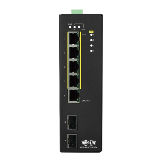
3. Hardware Description NGI-S05C2POE4 Front Panel 5 10/100/1000Base-T (4 PSE) ports + 2 100FX/Gigabit SFP slots Lite Managed Industrial PoE+ Ethernet Switch 3.1. Connectors The Switch utilizes ports with copper and SFP fiber port connectors functioning under Ethernet/Fast Ethernet/Gigabit Ethernet standards. - Page 14 Location: The NGI-S05C2POE4 can be DIN-Rail-mounted in cabinet or enclosure. Mounting the Switch Place the NGI-S05C2POE4 on the DIN rail from above using the slot and push the front of the switch toward the mounting surface until it snaps into place with a click sound.
- Page 15 This product is intended to be mounted to a well-grounded mounting surface, such as a metal panel. Caution: The earth connection must not be removed unless all power supply connection has been disconnected. Caution: The device is installed in a restricted-access location it has a separate protective earthing terminal on the chassis that must be permanently connected to earth ground to adequately ground the chassis and protect the operator from electrical hazards.
- Page 16 Warning Use copper conductors only, 60/75˚C (140/167°F), tighten to 0.56 N•m (5 lb•in). The wire gauge for the terminal block should range between 12~24 AWG. Redundant Power Input: Insert the “4-pin Mini-DIN” connector into “4-pin Mini-DIN” receiver and “Terminal Block” into terminal block receptor. Connect power cables to terminal block: Use your finger to press the orange plug on top of terminal block connector to insert power cables WARNING...
-
Page 17: Led Indicators
Manual Reboot / Reset Switch Switch contains “Reset” button through which you can manually reboot or reload to factory default settings. If press “Reset” button for more than 2 seconds, the Switch will be rebooted If press “Reset” button for more than 5 seconds, the Switch will be reloaded to factory ... - Page 18 1. This device may not cause harmful interference. 2. This device must accept any interference received including interference that may cause undesired operation. ATTENTION If the equipment is used in a manner not specified by the Tripp Lite, the protection provided by the equipment may be impaired.
-
Page 19: Configuration
4. Configuration Initially, the new device connects the network using default IP (192.168.0.254). Access the IP address to enter the Wizard. After three seconds the “Welcome” screen will switch to the set-up screen as shown below. The following flow chart illustrates the installation and subsequent steps after plug in. - Page 20 Step 2: IP Address is to configure the management IP user can select DHCP mode or static mode to configure the switch IP as shown below...
- Page 21 Step 3: Access Mode is to access the device have 2 options Security mode (HTTPs, SSH, and SNMPv3) and Normal mode (HTTPs, SSH, SNMPv3, HTTP, TELNET, and SNMPv1/v2). Default: Username: admin Password: admin After successful completion of the settings, the web-link will take you to the “Topology Map” as landing page shown below where you can access the Dashboard, Login, and Information.
-
Page 22: Dashboard Settings
4.2. Dashboard Settings The dashboard setting enables you to control the performance of the switch like CPU, Memory, Port Tx Usage, Port Rx Usage. Learn option to obtain to port registration information. Parameter Description Port Registration Learn Learn This field is to obtain the port registration information. Reset Reset option to reset the port registration information Port Link Down Statistics... - Page 23 User can configure threshold value to normal, alert, critical CPU Usage percentage or disable the feature. User can configure threshold value to normal, alert, critical Memory Usage percentage or disable the feature. User can configure threshold value to normal, alert, critical Port Tx Usage percentage of the interface Tx usage or disable the feature.
-
Page 24: Power Over Ethernet (Poe)
4.3. Power over Ethernet (PoE) Power over Ethernet (or PoE) technology describes a system to pass electrical power safely, along with data, on Ethernet cabling. PoE requires category 5 cable or higher for high power levels, but can operate with category 3 cable for low power levels. Power can come from a power supply within a PoE-enabled networking device such as an Ethernet switch or can be injected into a cable run with a mid-span power supply. -
Page 25: Poe Settings
Power Devices Power levels available Classification current Power range Class Usage Class description [mA] [Watt] Default 0 - 4 0.44 - 12.94 Classification unimplemented Optional 9 - 12 0.44 - 3.84 Very Low power Optional 17 - 20 3.84 - 6.49 Low power Optional 26 - 30 6.49 - 12.95 Mid power... -
Page 26: Web Configuration
4.3.1.2. Web Configuration Parameter Description PoE Configuration Settings Selects Enable to enable the PoE function on the Switch. State Selects Disable to disable the PoE function on the Switch. Total PoE power budget of the device can be configured Max Power Total Power Limit Range is 240 (W). -
Page 27: Pd Alive Check
Total Power (W) Displays the total power that the Switch supports. Total Power Displays the total consuming power for all of the PDs. Consumption (W) Port Display the Port No. State Displays the PoE state for the specific port (Enable/ Disable). LLDP Alloc Displays the status of allocated by LLDP MED. -
Page 28: Cli Configuration
4.3.2.1. CLI Configuration Node Command Description enable show pd-alive This command displays the configuration of the PD Alive Check. enable configure terminal This command changes the node to configure node. configure pd-alive (disable|enable) This command disables or enables the global PD Alive Check for the Switch. -
Page 29: Power Delay
PD Alive Check Settings State Enables/Disables the global PD Alive Check. Port Selects a port or a range of ports which you want to configure. State Enables/Disables the PD Alive Check for the specific port(s). IP Address Specifies the Host IP address which connects to the port. The interval to send the packet probes to check if the host is still Interval alive. - Page 30 Power Delay for the range of ports.
-
Page 31: Web Configuration
4.3.3.2. Web Configuration Parameter Description Power Delay Settings Port Selects a port or a range of ports which you want to configure. State Enables / Disables the PoE Power Delay for the specific ports. Time The delay time for the specific ports. Apply Click Apply to take effect the settings. -
Page 32: Poe Schedule
4.3.4. PoE Schedule The function has a global state configuration. If the global state configuration is disabled. The Switch will not perform the schedule function. If the global state is enabled, the Switch will check every port’s configurations. If the port’s check configuration is NO for a specific day, the Switch will not perform action for the specific port. -
Page 33: Web Configuration
4.3.4.2. Web Configuration Parameter Description Schedule Settings Port Selects a port that you want to configure the PoE schedule function. Select PoE schedule on interface enable/disable by default it is State Disabled Week Select a week day that you want to configure the schedule. Enables or Disables the PoE schedule on the specific port for a Check defined time period. -
Page 34: Port Settings
4.4. Port Settings State In port configuration you can enable or disable the port. If the port is disabled the port remains off without any operation. To keep it operating, place the port in enable state. Speed It defines in which speed the port should operate. The speeds that it can operate are 10/100/1000Mbps. -
Page 35: Port Configuration
connection speed and duplex mode that both ends support. When auto-negotiation is turned on, a port on the Switch negotiates with the peer automatically to determine the connection speed and duplex mode. If the peer port does not support auto-negotiation or turns off this feature, the Switch determines the connection speed by detecting the signal on the cable and using half duplex mode. - Page 36 for the specific port. interface no description This command configures the default port description. configure interface range gigabitethernet1/0/ This command enters the if-range PORTLISTS configure node. if-range description STRINGs This command configures a description for the specific ports. if-range no description This command configures the default port description for the specific ports.
-
Page 37: Web Configuration
4.4.1.2. Web Configuration Parameter Description Port Settings Port Selects a port or a range of ports on which to configure the port. State Select option to enable / disable the port. Speed/duplex Select a speed/duplex for port(s). Flow Control User can configure flow control on interface on/off Click Apply to take effect the settings. -
Page 38: Loop Detection
4.4.2. Loop Detection Loop detection is designed to handle loop problems on the edge of your network. This can occur when a port is connected to a Switch that is in a loop state. Loop state occurs as a result of human error. -
Page 39: Cli Configuration
4.4.2.1. CLI Configuration Node Command Description enable show loop-detection This command displays the current loop detection configurations. enable configure terminal This command changes the node to configure node. configure loop-detection This command disables / enables the loop detection (disable|enable) on the switch. configure loop-detection address This command configures the destination MAC for... -
Page 40: Web Configuration
4.4.2.2. Web Configuration Parameter Description Configuration Settings User can configure loop-detection state enable/disable globally by State default it is disabled. Enter the destination MAC address the probe packets will be sent to. MAC Address If the port receives these same packets the port will be shut down. Port Select a port on which to configure loop guard protection. - Page 41 State This field displays if the loop guard feature is enabled. Status This field displays if the port is blocked. If the port is blocked by loop detection, you can click “Unblock” to Manual Recovery recovery it manually. Recovery State This field displays if the loop recovery feature is enabled.
-
Page 42: Port Priority
4.4.3. Port Priority Typically, networks operate on a best-effort delivery basis, which means that all traffic has equal priority and an equal chance of being delivered in a timely manner. When congestion occurs, all traffic has an equal chance of being dropped. Using Port Priority feature, you can select specific network traffic, and prioritize it according to its relative importance. -
Page 43: Web Configuration
4.4.3.2. Web Configuration Parameter Description Port Priority Settings Selects a port or a range of ports on which to configure the Port priority. Select a priority for packets received by the port. Only packets Priority without 802.1p priority tagged will be applied the priority you set here. -
Page 44: Ring Settings
4.5. Ring Settings 4.5.1. ERPS The ITU-T G.8032 Ethernet Ring Protection Switching feature implements protection switching mechanisms for Ethernet layer ring topologies. This feature uses the G.8032 Ethernet Ring Protection (ERP) protocol, defined in ITU-T G.8032, to provide protection for Ethernet traffic in a ring topology, while ensuring that no loops are within the ring at the Ethernet layer. - Page 45 Wait to restore (WTR) timer -- The RPL owner uses the WTR timer. The WTR timer applies to the revertive mode to prevent frequent triggering of the protection switching due to port flapping or intermittent signal failure defects. When this timer expires, the RPL owner sends a R-APS (NR, RB) through the ring.
-
Page 46: Erps
error. If you still want to use this instance, you can change the Control VLAN to same as the control vlan of the instance first. And then configures the instance. 4.5.1.1. ERPS 4.5.1.1.1. CLI Configuration Node Command Description enable show erps This command displays the ERPS configurations. -
Page 47: Web Configuration
4.5.1.1.2. Web Configuration Parameter Description ERPS Global Settings Global State Enables / disables the global ERPS state. ERPS Ring Settings Ring ID Configures the ring ID. The Valid value is from 1 to 255. State Enables/ disables the ring state. Ring Name Configures the ring name.(Up to 32 characters) Revertive... - Page 48 Configures the Control MEL for the ring. The Valid value is from 0 to 7. The default is 7. Configures the Guard time for the ring. The Valid value is from 10 to Guard Timer 2000 (ms). Configures the left port and its type for the ring. The valid port type is Left Port one of Owner, Neighbor or Normal.
-
Page 49: Erps Instance
4.5.1.2. ERPS Instance 4.5.1.2.1. CLI Configuration Node Command Description enable show erps instance This command displays all of the ERPS instance configurations. enable show erps instance This command displays the specific ERPS instance <1-2> configurations. enable configure terminal This command changes the node to configure node. configure erps instance This command enters the instance configure node. -
Page 50: Stp/Rstp
Instance The instance ID. Control VLAN The control VLAN of the instance. Data VLAN The data VLANs of the instance. 4.5.2. STP/RSTP (R)STP detects and breaks network loops and provides backup links between switches, bridges or routers. It allows a Switch to interact with other (R)STP compliant switches in your network to ensure that only one path exists between any two stations on the network. - Page 51 cost to the root among the bridges connected to the LAN. Forward Time (Forward Delay): This is the maximum time (in seconds) the Switch will wait before changing states. This delay is required because every switch must receive information about topology changes before it starts to forward frames.
- Page 52 The Spanning Tree Protocol (STP) is defined in the IEEE Standard 802.1D. As the name suggests, it creates a spanning tree within a mesh network of connected layer-2 bridges (typically Ethernet switches), and disables those links that are not part of the tree, leaving a single active path between any two network nodes.
- Page 53 Transmission Limit: This is used to configure the minimum interval between the transmission of consecutive RSTP BPDUs. This function can only be enabled in RSTP mode. The range is from 1 to 10 seconds. Hello Time: Set the time at which the root switch transmits a configuration message. The range is from 1 to 10 seconds.
-
Page 54: Stp Configuration
4.5.2.1. STP Configuration 4.5.2.1.1. CLI Configuration Node Command Description enable show spanning-tree This command displays the spanning tree information active for only active port(s). enable show spanning-tree This command displays the spanning tree information blockedports for only blocked port(s). enable show spanning-tree This command displays the spanning tree information statistics PORT_ID... -
Page 55: Web Configuration
configure interface range This command enters the if-range configure node. gigabitethernet1/0/ PORTLISTS if-range spanning-tree This command configures enables/disables the STP (disable|enable) function for the specific port. 4.5.2.1.2. Web Configuration Parameter Description STP Settings Select Enabled to use Spanning Tree Protocol (STP) or Rapid State Spanning Tree Protocol (RSTP). - Page 56 a new root port is selected from among the Switch ports attached to the network. The allowed range is 6 to 40 seconds. This is the time interval in seconds between BPDU (Bridge Protocol Hello Time Data Units) configuration message generations by the root switch. The allowed range is 1 to 10 seconds.
-
Page 57: Stp Port Settings
4.5.2.2. STP Port Settings 4.5.2.2.1. CLI Configuration Node Command Description enable show spanning-tree This command displays the spanning tree information port detail PORT_ID for the interface port. enable configure terminal This command changes the node to configure node. configure interface IFNAME This command enters the interface configure node. -
Page 58: Web Configuration
if-range no spanning-tree cost This command configures the path cost to default for the specific port. if-range spanning-tree This command configures the port priority for the port-priority <0-240> specific port. Default: 128. if-range no spanning-tree This command configures the port priority to default for port-priority the specific port. - Page 59 Apply Click Apply to take effect the settings. Refresh Click Refresh to begin configuring this screen afresh. STP Port Status The port role. Should be one of the Alternated / Designated / Root / Role Backup / None. The port’s status. Should be one of the Discarding / Blocking / Status Listening / Learning / Forwarding / Disabled.
-
Page 60: System Settings
4.6. System Settings 4.6.1. System Settings Host Name The hostname is same as the SNMP system name. Its length is up to 64 characters. Management VLAN The hosts connect to the ports belong to the Management VLAN can manage the Switch only. -
Page 61: Igmp Snooping
4.6.1.3. IGMP Snooping The IGMP snooping is for multicast traffic. The Switch can passively snoop on IGMP packets transferred between IP multicast routers/switches and IP multicast hosts to learn the IP multicast group membership. It checks IGMP packets passing through it, picks out the group registration information, and configures multicasting accordingly. -
Page 62: Ipv4 Settings
VLANLISTS on a VLAN or range of VLANs. configure no igmp-snooping vlan This command disables the IGMP snooping function VLANLISTS on a VLAN or range of VLANs. configure igmp-snooping This command configures the process for unknown unknown-multicast multicast packets when the IGMP snooping function (drop|flooding) is enabled. -
Page 63: Web Configuration
address from DHCP server. next_restart: The settings will take effect on next system restart. Example: The procedures to configure an IP address for the Switch. To enter the configure node. L2SWITCH#configure terminal L2SWITCH(config)# To enter the ETH0 interface node. L2SWITCH(config)#interface eth0 L2SWITCH(config-if)# To get an IP address from a DHCP server. - Page 64 System Settings Enter up to 64 alphanumeric characters for the name of your Hostname Switch. The hostname should be the combination of the digit or the alphabet or hyphens (-) or underscores (_). Management VLAN This field is to configure Management VLAN. Modbus TCP Settings Modbus TCP State Select option to enable / disable the Modbus TCP on the Switch.
-
Page 65: Network Topology
5. Network Topology The Topology Map is a feature to check neighbor devices’ information or to configure them easily. Click the Topology Map, the system will display topology as below. All devices connect to the Switch directly and support LLDP will be displayed on the screen. Such as below figure, the Switch is its neighbor device. -
Page 66: Map Settings
5.1. Map Settings The Topology Map function allow user to upload a picture file as the background or just change the background color. For special purpose, it also allow user to upload a device picture as an ICON for the port. That is, it will not care what device is connected to the port. Notice: These image files need be uploaded with web configuration. -
Page 67: Web Configuration
5.1.2. Web Configuration Background You can upload your company floor layout plan picture in to the background image so that you can identify easily where the switch has been placed. Picture To choose a file which you want to display it in the background and the Preview window will display your select immediately. - Page 68 Color Allow user to select standard color for the background and the Preview window will display your select immediately. Alter Device ICON: The settings allow user to remap the device ICON in the Topology Map. Parameter Description Background Select “Picture” to upload a picture as the background of the Topology Map.
- Page 69 To upload a picture for the device ICON remapping. Image The picture should be in GIF/PNG/JPG/BMP format and its file size cannot be larger than 40 KB. Preview To display your configurations and then make decision if apply your configurations.
-
Page 70: Neighbor Devices
5.2. Neighbor Devices 5.2.1. LLDP The Link Layer Discovery Protocol (LLDP) specified in this standard allows stations attached to an IEEE 802 LAN to advertise, to other stations attached to the same IEEE 802 LAN, the major capabilities provided by the system incorporating that station, the management address or addresses of the entity or entities that provide management of those capabilities, and the identification of the station’s point of attachment to the IEEE 802 LAN required by those management entity or entities. -
Page 71: Web Configuration
5.2.1.2. Web Configuration Parameter Description LLDP Settings State Globally enables / disables the LLDP on the Switch. Tx Interval Configures the interval to transmit the LLDP packets. Configures the tx-hold time which determines the TTL of the Tx Hold Switch’s message. (TTL=tx-hold * tx-interval) Time To Live The hold time for the Switch’s information. -
Page 72: Manual Registration
Management The neighbor’s management address. Address Time To Live The hold time for the neighbor’s information. 5.2.2. Manual Registration If devices do not support LLDP and ONVIF, the user must enter the details manually during manual registration. This function support four types: IP-Cam, PLC, Switch and PC. 5.2.2.1. -
Page 73: Web Configuration
5.2.2.2. Web Configuration For devices that do not support ONVIF or LLDP, the user can input the device’s MAC address. The Switch will then discover the device and display it on the Lamungan Map. Parameter Description Manual Registration Settings Type The kind of devices connected to the Switch. -
Page 74: Onvif
5.2.3. ONVIF ONVIF is an open industry forum that provides and promotes standardized interfaces for effective interoperability of IP-based physical security products. The Switch use ONVIF to discovery if there is ONVIF device connected to the Switch. ONVIF settings and ONVIF Neighbor The page show the detail information about ONVIF settings and ONVIF devices connected to the Switch. -
Page 75: Web Configuration
5.2.3.2. Web Configuration Parameter Description ONVIF Settings Select option to enable / disable the ONVIF feature on the State Switch. Configures the sending ONVIF discovery packet interval. Tx Interval Valid range is 6 ~ 3600 seconds. Click Apply to take effect the settings. Apply Click Refresh to begin configuring this screen afresh. - Page 76 MAC Address The MAC address on the ONVIF device. VLAN ID The VLAN ID of the ONVIF device join. Product Name Name of the product added. Product Type What kind of product that is added. Model Model of the product. Location Location where it is placed.
-
Page 77: Topology Map
5.3. Topology Map The Topology Map is a feature to check neighbor devices’ information or to configure them easily. Click the Topology Map, the system will display topology as below. All devices connect to the Switch directly and support LLDP will be displayed on the screen. If the neighbor device is a Switch which supports Lamungan server function, click the right key of the mouse. - Page 78 You can view the basic details of the devices connected to the host, by placing the cursor on it. When there is something wrong with the device, the screen will appear as shown so that you can find the details of events that have gone wrong, and correct them.
-
Page 79: Client Switch Management
5.3.1. Client Switch Management By right-clicking on the neighbor non-lite Switch, this menu will appear and you can configure as shown. Non-Lite Switch Menu: Save All Device Location To fix the location of all devices on the map, so that it restores its places after refresh. Login Web GUI ... -
Page 80: Quick Configuration Menu
5.3.2. Quick Configuration Menu By right-clicking on the neighbor lite management switch, this menu will appear and you can configure as shown. By right-clicking on the neighbor switch (only lite management switches), this menu will appear and you can configure as shown. -
Page 81: Ip Configuration
5.3.2.1. IP Configuration Parameter Description IPv4 Settings Configures the DHCP client function for your Switch. DHCP Client Enable means the Switch get an IP address from a DHCP server. Configures a static IPv4 address for your Switch in dotted IP Address decimal notation. -
Page 82: Loop Detection Configuration
5.3.2.2. Loop Detection Configuration Parameter Description Loop Detection Settings State Select this option to enable / disable loop detection on the Switch. Port Select a port or a range of ports which to configure loop detection. Select option to enable/disable the loop detection feature on State port(s). -
Page 83: Port Configuration
5.3.2.3. Port Configuration Parameter Description Port Settings Port Selects a port or a range of ports on which to configure the port. State Select option to enable / disable the port. Apply Click Apply to take effect the settings. Refresh Click Refresh to begin configuring this screen afresh. -
Page 84: Port Mirror Configuration
5.3.2.4. Port Mirror Configuration Parameter Description Port Mirror Settings Select option to enable / disable the port mirroring feature on the State Switch. Selects a port which packets received and transmitted by this port Source Port will be copied to the destination port. Destination Port Select a port which connects to a network traffic analyzer. -
Page 85: Storm Control Configuration
Selects a port or a range of ports on which to configure the Port priority. Priority Selects “Low”, “Medium” and “High” priority for the port(s). Apply Click Apply to take effect the settings. Refresh Click Refresh to begin configuring this screen afresh. Port Priority Status Port This field displays a port number. -
Page 86: Save Configuration
Broadcast This field displays the broadcast storm control state on the port. This field displays the DLF storm control state on the port. 5.3.2.7. Save Configuration Parameter Description Save Configuration Click Save Configuration to save the current running Save Configuration configuration to the NVRAM. -
Page 87: Security
6. Security 6.1. 802.1X IEEE 802.1X is an IEEE Standard for port-based Network Access Control ("port" meaning a single point of attachment to the LAN infrastructure). It is part of the IEEE 802.1 group of networking protocols. It provides an authentication mechanism to devices wishing to attach to a LAN, either establishing a point-to-point connection or preventing it if authentication fails. - Page 88 Local User Accounts By storing user profiles locally on the Switch, your Switch is able to authenticate users without interacting with a network authentication server. However, there is a limit on the number of users you may authenticate in this way. Guest VLAN: The Guest VLAN in IEEE 802.1x port authentication on the switch to provide limited services to clients, such as downloading the IEEE 802.1x client.
-
Page 89: Configuration
6.1.1. Configuration 6.1.1.1. CLI Configuration Node Command Description enable show dot1x This command displays the current 802.1x configurations. enable show dot1x username This command displays the current user accounts for the local authentication. enable show dot1x This command displays the local accounting records. accounting-record enable configure terminal... -
Page 90: Web Configuration
6.1.1.2. Web Configuration Parameter Description Global Settings Select Enable to permit 802.1 x authentications on the Switch. State Note: You must first enable 802.1 x authentications on the Switch before configuring it on each port. Select whether to use Local or RADIUS as the authentication method. The Local method of authentication uses the “guest”... - Page 91 shared between the external RADIUS server and the Switch. This key is not sent over the network. This key must be the same on the external RADIUS server and the Switch. Second Radius This is the backup server used only when the Primary Radius Server Server is down.
-
Page 92: Port Configuration
6.1.2. Port Configuration 6.1.2.1. CLI Configuration Node Command Description enable show dot1x port This command displays the current 802.1x PORTLISTS configurations for the specific port. enable configure terminal This command changes the node to configure node. configure interface IFNAME This command enters the interface configure node. interface dot1x This command configures the control direction for... -
Page 93: Web Configuration
6.1.2.2. Web Configuration Parameter Description Port Settings Port Select a port number to configure. Select Enable to permit 802.1 x authentications on the port. 802.1x State You must first enable 802.1 x authentications on the Switch before configuring it on each port. Select Both to drop incoming and outgoing packets on the port Admin Control when a user has not passed 802.1x port authentication. - Page 94 Select Disable to disable Guest VLAN on the port. Guest VLAN Select Enable to enable Guest VLAN on the port. Specify the amount of times the Switch will try to connect to the Max-req Time authentication server before determining the server is down. The acceptable range for this field is 1 to 10 times.
-
Page 95: Acl
This field displays how long the Switch will wait before Supp timeout communicating with the server. This field displays how long the Switch will wait before Server timeout communicating with the client. 6.2. ACL Access control list (ACL) is a list of permissions attached to an object. The list specifies who or what is allowed to access the object and what operations are allowed to be performed on the object. - Page 96 no destination mac This command removes the destination MAC from the profile. ethertype STRING This command configures the ether type for the profile. Where the STRING is a hex-decimal value. e.g.: 08AA. no ethertype This command removes the limitation of the ether type from the profile.
- Page 97 Example: L2SWITCH#configure terminal L2SWITCH(config)#access-list 111 L2SWITCH(config-acl)#vlan 2 L2SWITCH(config-acl)#source interface 1 L2SWITCH(config-acl)#show Profile Name: 111 Activate: disabled VLAN: 2 Source Interface: 1 Destination MAC Address: any Source MAC Address: any Ethernet Type: any Source IP Address: any Destination IP Address: any Source Application: any Destination Application: any Note: Any: Don’t care.
-
Page 98: Web Configuration
6.2.2. Web Configuration Parameter Description Access Control List Settings Profile Name The access control profile name. Selects Disables / Drop / Permits action for the profile. State Ethernet Type Configures the Ethernet type of the packets that you want to filter. VLAN Configures the VLAN of the packets that you want to filter. - Page 99 Configures the bitmap mask of the destination MAC of the packets that you want to filter. Mask of If the Destination MAC field has been configured and this field is Destination MAC empty, it means the profile will filter the one MAC configured in Destination MAC field.
-
Page 100: Port Security
6.3. Port Security The Switch will learn the MAC address of the device directly connected to a particular port and allow traffic through. We will ask the question: “How do we control who and how many can connect to a switch port?” This is where port security can assist us. The Switch allow us to control which devices can connect to a switch port or how many of them can connect to it (such as when a hub or another switch is connected to the port). -
Page 101: Web Configuration
6.3.2. Web Configuration Parameter Description Port Security Settings Port Security Select Enable/Disable to permit Port Security on the Switch. Port Select a port number to configure. Select Enable/Disable to permit Port Security on the port. State The maximum number of MAC addresses allowed per interface. Maximum MAC The acceptable range is 1 to 1000. -
Page 102: Server Control
6.4. Server Control The function allows users to enable or disable the HTTP, HTTPS, SNMPv1/v2c, SNMPv3, SSH, Telnet service individually. 6.4.1. CLI Configuration Node Command Description enable show server status This command displays the current server status. enable configure terminal This command changes the node to configure node. -
Page 103: Web Configuration
6.4.2. Web Configuration Parameter Description Server Settings HTTP Server State Selects Enable or Disable to enable or disable the HTTP service. HTTPS Server Selects Enable or Disable to enable or disable the HTTPS service. State SNMPv1/v2c Selects Enable or Disable to enable or disable the SNMPv1/v2c Server State service. - Page 104 Status SNMPv1/v2c Server Displays the current SNMPv1/v2c service status. Status SNMPv3 Server Displays the current SNMPv3 service status. Status SSH Server Status Displays the current SSH service status. Telnet Server Status Displays the current Telnet service status.
-
Page 105: Storm Control
6.5. Storm Control 6.5.1. Alarm Threshold When the selected packet rate is over the alarm threshold, the Switch will send syslog alarm to syslog server. 6.5.1.1. CLI Configuration Node Command Description enable show bandwidth-limit This command displays the current rate control configurations. - Page 106 Parameter Description Alarm Threshold Settings State Select option to enable / disable the alarm threshold feature on the Switch. Port Selects a port or a range of ports on which to configure the alarm threshold. State Selects Enable / Disable the alarm threshold for the port(s). Packet Type Selects packet type one of Broadcast / Multicast / Bcast+Mcast.
-
Page 107: Storm Control
6.5.2. Storm Control A broadcast storm means that your network is overwhelmed with constant broadcast or multicast traffic. Broadcast storms can eventually lead to a complete loss of network connectivity as the packets proliferate. Storm Control protects the Switch bandwidth from flooding packets, including broadcast packets, multicast packets and destination lookup failure (DLF). -
Page 108: Web Configuration
6.5.2.2. Web Configuration Parameter Description Storm Control Settings Select individual port number or range for which you want to configure Port storm control settings. Configure the packet rate in pps to allow on interfaces. Disable for 0 and Rate ranges 1 ~ 5000. Type Click the check box to select Multicast / Broadcast / DLF storm control. -
Page 109: Vlan
6.6. VLAN 6.6.1. Port Isolation The port isolation is a port-based virtual LAN feature. It partitions the switching ports into virtual private domains designated on a per port basis. Data switching outside of the port’s private domain is not allowed. It will ignore the packets’ tag VLAN information. This feature is a per port setting to configure the egress port(s) for the specific port to forward its received packets. -
Page 110: Web Configuration
6.6.1.2. Web Configuration Parameter Description Port Isolation Settings Select a port number to configure its port isolation settings. Select All Ports to configure the port isolation settings for all ports Port on the Switch. An egress port is an outgoing port, that is, a port through which a data packet leaves. -
Page 111: Vlan
6.6.2. VLAN 802.1Q VLAN A virtual LAN, commonly known as a VLAN, is a group of hosts with a common set of requirements that communicate as if they were attached to the Broadcast domain, regardless of their physical location. A VLAN has the same attributes as a physical LAN, but it allows for end stations to be grouped together even if they are not located on the same network switch. -
Page 112: Cli Configuration
With port-based VLAN membership, the port is assigned to a specific VLAN independent of the user or system attached to the port. This means all users attached to the port should be members of the same VLAN. The network administrator typically performs the VLAN assignment. - Page 113 enable show vlan VLANID This command displays the VLAN configurations. enable configure terminal This command changes the node to configure node. configure vlan <1~4094> This command enables a VLAN and enters the VLAN node. configure no vlan <1~4094> This command deletes a VLAN. vlan show This command displays the current VLAN...
-
Page 114: Web Configuration
6.6.2.2. Web Configuration Parameter Description VLAN Settings Select a port number to configure from the drop-down box. Port Select All to configure all ports at the same time. Role Select role on interface as access or trunk. User can configure maximum of 5 VLAN’s on each interface in the VLAN format 1,3,7,10,25. -
Page 115: Diagnostic
7. Diagnostic 7.1. Alarm The feature displays if there are any abnormal situation need process immediately. Alarm LED: On - When any alarm events happen. The web pages show you the detail alarm reason. 7.1.1. CLI Configuration Node Command Description enable show alarm-info This command displays alarm information. -
Page 116: Web Configuration
port PORT_ID mirroring. configure mirror source ports This command adds a port or a range of ports as the PORT_LIST mode source ports of the port mirroring. (both|ingress|egress) This command removes a port or a range of ports from configure no mirror source ports PORT_LIST the source ports of the port mirroring. - Page 117 Use this field only if you want to make some settings the same for all ports. Use this field first to set the common settings and then make adjustments on a port-by-port basis. Source Port Selects a port to monitor packets received and transmit or both. Select a port to monitor as destination for the source port.
-
Page 118: Port Statistics
7.3. Port Statistics This feature helps users to monitor the ports’ statistics, to display the link up ports’ traffic utilization only. 7.3.1. CLI Configuration Node Command Description enable show port-statistics This command displays the link up ports’ statistics. Example : L2SWITCH#show port-statistics Packets Bytes... -
Page 119: Port Utilization
7.4. Port Utilization This feature helps users to monitor the ports’ traffic utilization, to display the link up ports’ traffic utilization only. 7.4.1. CLI Configuration Node Command Description enable show port-utilization This command displays the link up ports’ traffic <bps|Kbps|Mbps> utilization. -
Page 120: Syslog
Tx Utilization (bps) The field display Tx utilization in bps. 7.5. Syslog The syslog function records some of system information for debugging purpose. Each log message recorded with one of these levels, Alert / Critical / Error / Warning / Notice / Information. -
Page 121: Web Configuration
7.5.2. Web Configuration Parameter Description Enter the Syslog server IP address. Select Enable to activate switch sent log message to Syslog Server IP server when any new log message occurred. Apply Click Apply to take effect the settings. Refresh Click Refresh to begin configuring this screen afresh. Select Alert/Critical/Error/Warning/Notice/Information to Log Level choose which log message to want to see. -
Page 122: Utilization Threshold
7.6. Utilization Threshold This feature alerts the user when the packet rate in the particular port is above the required rate. 7.6.1. CLI Configuration Node Command Description enable configure terminal This command changes the node to configure node. configure port-utilization The command disables / enables the port utilization threshold threshold function globally. - Page 123 Alarm Threshold Settings Select option to enable / disable the alarm threshold feature on the State Switch. Selects a port or a range of ports on which to configure the alarm Port threshold. State Selects Enable / Disable the alarm threshold for the port(s). Configures the threshold rate.
-
Page 124: Management
8. Management 8.1. Simple Network Management Protocol (SNMP) Simple Network Management Protocol (SNMP) is used in network management systems to monitor network-attached devices for conditions that warrant administrative attention. SNMP is a component of the Internet Protocol Suite as defined by the Internet Engineering Task Force (IETF). -
Page 125: Web Configuration
8.1.1.2. Web Configuration Parameter Description SNMP Settings SNMP State Select option to enable / disable the SNMP on the Switch. System Name User can configure system name System Location User can configure the switch deployed location for reference User can configure System Contact person information like name or System Contact number Click Apply to take effect the settings. -
Page 126: Web Configuration
STRING (ro|rw) Permission(ro/rw), Trusted host IP/Subnet mask. trusted-host IPADDR/Subnet Mask Example: L2SWITCH#configure terminal L2SWITCH(config)#snmp community public rw trusted-host 192.168.200.106/24 8.1.2.2. Web Configuration Parameter Description Community Name Enter a Community string; this will act as a password for requests from the management station. -
Page 127: Snmp Event Settings
Click Refresh to begin configuring this screen afresh. Refresh Community Name List This field displays the index number of an entry. Community String This field displays the community string of an entry. Rights This field displays the right of an entry. Network ID of This field displays the network ID of trusted host of an entry. -
Page 128: Web Configuration
stp-topology-change stp-topology-change trap. (disable/enable) configure snmp trap-event This command enables/disables thetraffic-monitor traffic-monitor trap. (disable/enable) 8.1.3.2. Web Configuration Parameter Description Trap Event Settings Select all Enables all of trap events. Deselect All Disables all of trap events. Alarm-Over-Heat Trap when system’s temperature is too high. Alarm-Over-Load Trap when system is over load. - Page 129 Apply Click Apply to configure the settings. Refresh Click Refresh to begin configuring this screen afresh.
-
Page 130: Port Trap Event
8.1.4. Port Trap Event The features allow users to enable/disables port-link-change trap notification by individual port. 8.1.4.1. CLI Configuration Node Command Description enable show snmp port-link-change-trap This command displays the SNMP port link-change trap configurations. enable configure terminal This command changes the node to configure node. - Page 131 Apply Click Apply to configure the settings. Refresh Click Refresh to begin configuring this screen afresh.
-
Page 132: Snmp Trap Receiver
8.1.5. SNMP Trap Receiver The features allow users to configure trap receiver configuration. 8.1.5.1. CLI Configuration Node Command Description enable configure terminal This command changes the node to configure node. configure snmp trap-receiver This command configures the trap receiver’s IPADDR (v1|v2c) configurations, including the IP address, version (v1 or STRING v2c) and community String. - Page 133 Action Click Delete to remove a configured trap receiver station.
-
Page 134: Snmpv3
8.2. SNMPv3 SNMP version 3 (SNMPv3) supports authentication and encryption. SNMPv3 uses the user-based security model (USM) for message security and the view-based access control model (VACM) for access control. USM specifies authentication and encryption. 8.2.1. SNMPv3 Group 8.2.1.1. CLI Configuration Node Command Description... -
Page 135: Snmpv3 User
Group Name Enter the v3 user name. Security Level Select the security level of the v3 group to use. Note that if a group is defined without a read view than all objects are Read View available to read. (default value is none.) if no write or notify view is defined, no write access is granted and no Write View objects can send notifications to members of the group. -
Page 136: Web Configuration
8.2.2.2. Web Configuration Parameter Description User Settings User Name Enter the v3 user name. Group Name Map the v3 user name into a group name. Select the security level of the v3 user to use. noauth means no authentication and no encryption. Security Level auth means messages are authenticated but not encrypted. -
Page 137: Snmpv3 View
User Name This field displays the v3 user name. Group Name This field displays the group name which the v3 user mapping. Auth Protocol These fields display the security level to this v3 user. Priv Protocol Rowstatus This field displays the v3 user row status. Action Click Delete to remove a v3 user. -
Page 138: Web Configuration
8.2.3.2. Web Configuration Parameter Description View Settings Enter the v3 view name for creating an entry in the SNMPv3 MIB View Name view table. The OID defining the root of the subtree to add to (or exclude from) View Subtree the named view. -
Page 139: Cli Configuration
UDP Port: 123. Daylight saving is a period from late spring to early fall when many countries set their clocks ahead of normal local time by one hour to give more daytime light in the evening. Note: The SNTP server always replies the UTC current time. When the Switch receives the SNTP reply time, the Switch will adjust the time with the time zone configuration and then configure the time to the Switch. -
Page 140: Web Configuration
Wednesday | Thursday | Friday | Saturday) MONTH HOUR configure time ntp-server This command disables / enables the NTP server (disable|enable) state. configure time ntp-server This command sets the IP address of your time IP_ADDRESS server. configure time timezone STRING Configures the time difference between UTC (formerly known as GMT) and your time zone. - Page 141 appear in the Current Date and Current Time fields after you click Apply. Enable Select this option to use Network Time Protocol (NTP) for the Network Time time service. Protocol Select a pre-designated time server or type the IP address or type NTP Server the domain name of your time server.
- Page 142 GMT or UTC). So in the European Union you would select Last, Sunday, 10(October) and the last field depends on your time zone. In Germany for instance, you would select 2:00 because Germany's time zone is one hour ahead of GMT or UTC (GMT+1).
-
Page 143: System Information
8.4. System Information The System Information window appears each time you log into the program. Alternatively, this window can be accessed by clicking System Information. 8.4.1. CLI Configuration Node Command Description enable show interface eth0 This command will display the interface et0 information. -
Page 144: System Management
Built Date This field displays the built date of the firmware. This field displays whether the DHCP client is enabled on the DHCP Client Switch. IP Address This field indicates the IP address of the Switch. Subnet Mask This field indicates the subnet mask of the Switch. Default Gateway This field indicates the default gateway of the Switch. - Page 145 configure archive download-config This command downloads configure file to URL_PATH user-default-config. user-default-config configure copy factory-default-config to This command copies factory-default-config user-default-config file to user-default-config file. configure copy startup-config to This command copies the startup-config file user-default-config to user-default-config file. There are three configuration files: startup-config.
-
Page 146: Web Configuration
8.5.1.2. Web Configuration Click the “Choose File” button to select the new configuration file which you want to upgrade it to the Switch. Click the “Upload” button to start the upgrade procedures. Click the “Download” button to download the current configurations to local host. Reset Configuration Click the “Reset”... -
Page 147: Firmware
8.5.2. Firmware Upgrade Firmware 8.5.2.1. CLI Configuration Node Command Description enable configure terminal This command changes the node to configure node. configure archive download-fw This command downloads a new copy of firmware file <URL PATH> from TFTP / FTP / HTTP server. Where <URL PATH>... -
Page 148: Reboot
8.5.3. Reboot 8.5.3.1. CLI Configuration Node Command Description enable configure terminal This command changes the node to configure node. configure reboot This command reboots the system. 8.5.3.2. Web Configuration Click the “Reboot” button to restart the Switch. -
Page 149: User Account
8.6. User Account The Switch allows users to create up to 6 dot1x user account and 6 non-dot1x user account. The user name and the password should be the combination of the digit or the alphabet. The last admin user account cannot be deleted. Users should input a valid user account to login the CLI or web management. -
Page 150: Web Configuration
8.6.2. Web Configuration Parameter Description User Account Settings User Name Type a new username or modify an existing one. Type a new password or modify an existing one. Enter up to 32 User Password alphanumeric or digit characters. Select with which group the user associates. admin (read and ser Authority write) or normal (read only) or dot1x(Dot1X user for local authentication). -
Page 151: Warranty & Product Registration
WARRANTY & PRODUCT REGISTRATION 3-Year Limited Warranty TRIPP LITE warrants its products to be free from defects in materials and workmanship for a period of three (3) years from the date of initial purchase. TRIPP LITE’s obligation under this warranty is limited to repairing or replacing (at its sole option) any such defective products. To obtain service under this warranty, you must obtain a Returned Material Authorization (RMA) number from TRIPP LITE or an authorized TRIPP LITE service center. - Page 152 Tripp Lite could void the user’s authority to operate this equipment. Tripp Lite has a policy of continuous improvement. Specifications are subject to change without notice. Photos and illustrations may differ slightly from actual products.