
Related Manuals for GE Proteus XR/a


Summary of Contents for GE Proteus XR/a
- Page 1 GE Medical Systems Technical Publications Direction 2259724-100 Revision 11 Proteus XR/a Operator Manual 0459 Copyright 2000, 2001, 2003, 2004, 2005, 2006 © By General Electric Company Operating Documentation...
- Page 2 PROTEUS XR/a GE MEDICAL SYSTEMS Operator Manual REV 11 DIRECTION 2259724-100 This page intentionally left blank...
- Page 3 PROTEUS XR/a GE MEDICAL SYSTEMS Operator Manual REV 11 DIRECTION 2259724-100 IMPORTANT!...X-RAY PROTECTION X-ray equipment if not properly used may cause injury. Accordingly, the instructions herein contained should be thoroughly read and understood by everyone who will use the equipment before you attempt to place this equipment in operation.
- Page 4 (and the accompanying electrical installations) are highly sophisticated, and special engineering competence is required. In performing all electrical work on these products, GE will use its own specially trained field engineers. All of GE’s electrical work on these products will comply with the requirements of the applicable electrical codes.
- Page 5 Directive. The location of the CE label on the product is described page 2-4. European registered place of business: GE Medical System Europe Quality Assurance and Safety Regulatory Manager BP 34 F 78533 BUC CEDEX FRANCED Tel: +33 (0) 1 30 70 40 40 •...
- Page 6 PROTEUS XR/a GE MEDICAL SYSTEMS Operator Manual REV 11 DIRECTION 2259724-100 This page intentionally left blank...
- Page 7 To provide reasonable protection against such interference, the Proteus XR/a System (32, 50, 65, 80kW) complies with emissions limits for a Group 1, Class A Medical Devices and has applicable immunity level as stated in EN 60601-1-2:2001.
- Page 8 Guidance and manufacturer’s declaration – Electromagnetic Emissions The Proteus XR/a system is suitable for use in the specified electromagnetic environment. The purchaser or user of the Proteus XR/a system should assure that it is used in an electromagnetic environment as described below:...
- Page 9 Guidance and manufacturer’s declaration - Electromagnetic Immunity (1) The Proteus XR/a system is suitable for use in the specified electromagnetic environment. The purchaser or user of the Proteus XR/a system should assure that it is used in an electromagnetic environment as described below:...
- Page 10 Guidance and manufacturer’s declaration - Electromagnetic Immunity (2) The Proteus XR/a system is suitable for use in the specified electromagnetic environment. The purchaser or user of the Proteus XR/a system should assure that it is used in an electromagnetic environment as described below:...
- Page 11 Operator Manual REV 11 DIRECTION 2259724-100 ELECTROMAGNETIC COMPATIBILITY (EMC) (CONT.) Recommended Separation Distances for Portable and Mobile RF Communications Equipment and the Proteus XR/a system Frequency of Transmitter 150KHz to 80 MHz 80 MHz to 800 MHz 800 MHz to 2,5 GHz Equation d= 1.2...
- Page 12 PROTEUS XR/a GE MEDICAL SYSTEMS Operator Manual REV 11 DIRECTION 2259724-100 This page intentionally left blank...
- Page 13 PROTEUS XR/a GE MEDICAL SYSTEMS Operator Manual REV 11 DIRECTION 2259724-100 SAFETY ELECTRIC SHOCK HAZARD! DO NOT REMOVE COVERS OR PANELS. GENERATOR CABINET CONTAINS HIGH VOLTAGE CIRCUITS FOR GENERATING WARNING AND CONTROLLING X-RAYS. PREVENT POSSIBLE ELECTRIC SHOCK BY LEAVING COVERS AND PANELS ON THE EQUIPMENT. THERE ARE NO OPERATOR SERVICEABLE PARTS OR ADJUSTMENTS INSIDE THE CABINETS UNDER THE TABLE.
- Page 14 PROTEUS XR/a GE MEDICAL SYSTEMS Operator Manual REV 11 DIRECTION 2259724-100 ESTABLISH EMERGENCY PROCEDURES ESTABLISH PROCEDURES FOR HANDLING THE PATIENT IN CASE OF THE LOSS OF RADIOGRAPHIC IMAGING OR OTHER SYSTEM FUNCTIONS DURING AN EXAM. ESTABLISH PROCEDURES FOR HANDLING THE PATIENT IN CASE OF THE LOSS OF RADIOGRAPHIC IMAGING OR OTHER SYSTEM FUNCTIONS DURING AN EXAM.
- Page 15 Satisfactory equipment performance requires the use of service personnel specially trained on x-ray apparatus. GE Medical Systems is responsible for the effects on safety, reliability, and performance only if the following conditions are met: •...
- Page 16 PROTEUS XR/a GE MEDICAL SYSTEMS Operator Manual REV 11 DIRECTION 2259724-100 This page intentionally left blank...
-
Page 17: Table Of Contents
Warning Signs and Labels 2-10 System Labeling SYSTEM DESCRIPTION System Components/Features HHS Compliance Compatibilities PROTEUS XR/A SYSTEM START UP AND SHUT DOWN Turn the power on Turn Power off Daily Warm Up Procedures System Status Display Radiography Control Key PROTEUS XR/A SYSTEM CONSOLE... - Page 18 REV 11 DIRECTION 2259724-100 TABLE OF CONTENTS (CONT.) CHAPTER TITLE PAGE NUMBER PROTEUS XR/A WALL STAND (GPCP No.: 2260354) COMPONENT Introduction Operation PROTEUS XR/A SG120 WALL STAND (GPCP No.: 2402562) COMPONENT Safe Operation Precautions Introduction Applications Operation ACCESSORIES 10-1 10-1 Introduction...
- Page 19 PROTEUS XR/a GE MEDICAL SYSTEMS Operator Manual REV 11 DIRECTION 2259724-100 REVISION HISTORY DATE TYPE OF MODIFICATION 10/01/2000 Initial production Release 20/07/2000 Add system function description and system specification 05/12/2000 Update OTS user’s interface description 01/02/2001 Update the regulatory requirements.
- Page 20 PROTEUS XR/a GE MEDICAL SYSTEMS Operator Manual REV 11 DIRECTION 2259724-100 LIST OF EFFECTIVE PAGES PAGE REVISION PAGE REVISION NUMBER NUMBER NUMBER NUMBER i thru xii Address page 1-1 thru 1-4 2-1 thru 2-2 3-1 thru 3-4 v thru xi...
-
Page 21: Ge Medical Systems Rev
PROTEUS XR/a GE MEDICAL SYSTEMS Operator Manual REV 11 DIRECTION 2259724-100 CHAPTER 1 PROTEUS XR/A QUICK START 1-1 Turn System On 1-2 Tube Warm-Up -Set Technique -Set Parameters -Take 2 Exposures 10 sec apart... -
Page 22: Set Technique Apr
PROTEUS XR/a GE MEDICAL SYSTEMS Operator Manual REV 11 DIRECTION 2259724-100 1-3 Set Technique APR -Select Category -Select Procedure -Take Exposure... -
Page 23: Set Manual Technique
PROTEUS XR/a GE MEDICAL SYSTEMS Operator Manual REV 11 DIRECTION 2259724-100 1-4 Set Manual Technique -Set Parameters -Set Technique -Take Exposure... -
Page 24: Set Aec Technique
PROTEUS XR/a GE MEDICAL SYSTEMS Operator Manual REV 11 DIRECTION 2259724-100 1-5 Set AEC Technique -Set Parameters Set Technique -Take Exposure... -
Page 25: Symbols
PROTEUS XR/a GE MEDICAL SYSTEMS Operator Manual REV 11 DIRECTION 2259724-100 CHAPTER 2 SYMBOLS Symbols used on this system and in its accompanying documents are shown and explained in this section. 2-1 Special Notices Caution advises of an avoidable condition that could cause minor CAUTION physical injury, or damage to equipment or data. -
Page 26: Power On And Off
Protective Earth (ground). Identifies any terminal that is intended for connection of an external protective conductor to protect against electrical shock in case of a fault. 2-7 Proteus XR/a Collimator / Eclipse Proteus Collimator Control for indicating radiation field by using light. 2-8 Emergency Button... -
Page 27: Warning Signs And Labels
Laser Warning Proteus XR/a Collimator Eclipse Proteus Collimator Note: If have, please confirm the collimator and wall stand you’ve chosen by referring to the next chapter. Table 2-1 MEANINGS OF PROTEUS XR/A SIGNS Illustration 2-1 PROTEUS XR/A SYSTEM WARNING SIGNS LOCATION... -
Page 28: System Labeling
REV 11 DIRECTION 2259724-100 2-10 System Labelling The labels for the Proteus XR/a system are found on the side panel of the Proteus XR/a cabinet. This label includes the CE mark for the entire system. See the following sketch. For other name plate location, see table 2-2. -
Page 29: System Description
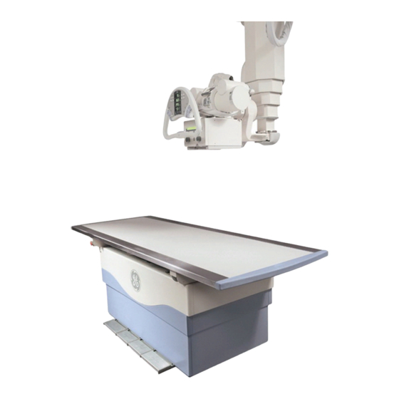
DIRECTION 2259724-100 CHAPTER 3 SYSTEM DESCRIPTION The Proteus XR/a X-ray System is a general radiographic system designed for a wide ra-nge of table, wall stand, wheelchair, and stretcher examinations. The system is especially suited for general-purpose radiography in hospitals, clinics, and private practices. - Page 30 COMPANY, OTHERWISE THEREOF THE LOSS OR DAMAGE IS NOT THE RESPONSIBILITY OF GE COMPANY. ILLUSTRATION 3-1 PROTEUS XR/A SYSTEM COMPONENTS The Proteus XR/a System is divided into basic components: 1. System Console 7. X-ray Tube 2. Elevating Table 8. Proteus XR/a Collimator 3.
-
Page 31: Hhs Compliance Compatibilities
Installers must indicate that the combination of installed HHS Certified Components is compatible on Form F3382 provided in Direction 46- 013894, System Field-Test For HHS. TABLE 3-1 PROTEUS XR/A SYSTEM HHS COMPLIANCE COMPATIBILITY LIST PRODUCT CATEGORY PRODUCT DESCRIPTION MODEL NUMBER... - Page 32 PROTEUS XR/a GE MEDICAL SYSTEMS Operator Manual REV 11 DIRECTION 2259724-100 This page intentionally left blank...
-
Page 33: Proteus Xr/A System Start Up And Shut Down
PROTEUS XR/a GE MEDICAL SYSTEMS Operator Manual REV 11 DIRECTION 2259724-100 CHAPTER 4 PROTEUS XR/A SYSTEM START UP AND SHUT DOWN Illustration 4-1 SYSTEM CONTROL PANEL POWER ON/OFF SYSTEM INDICATOR INCREASE /DECREASE EXPOSURE CONTROL 4-1 Turn the power on Illustration 4-2... -
Page 34: Daily Warm Up Procedures
PROTEUS XR/a GE MEDICAL SYSTEMS Operator Manual REV 11 DIRECTION 2259724-100 4-3 Daily Warm Up Procedures A tube warm up is recommended every day before the system is used. A tube warm-up should also be completed if the system is inactive for more than 2 hours. -
Page 35: Radiography Control Key
PROTEUS XR/a GE MEDICAL SYSTEMS Operator Manual REV 11 DIRECTION 2259724-100 4-5 Radiography Control Key ILLUSTRATION 4-4 HANDSWITCH LEVEL I TRIGGER LEVEL II An exposure can be made using the handswitch that is connected to the System Console, or by using the exposure keys on the System Console. - Page 36 PROTEUS XR/a GE MEDICAL SYSTEMS Operator Manual REV 11 DIRECTION 2259724-100 This page intentionally left blank...
-
Page 37: Proteus Xr/A System Console
Operator Manual REV 11 DIRECTION 2259724-100 CHAPTER 5 PROTEUS XR/A SYSTEM CONSOLE 5-1 Introduction This section introduces you to the Operator Console Display. A standard system screen is used as an example to acquaint you with the arrangement of screen information. - Page 38 PROTEUS XR/a GE MEDICAL SYSTEMS Operator Manual REV 11 DIRECTION 2259724-100 5-1-1 Group 1 Parameter Selection Area ILLUSTRATION 5-2 PARAMETER SELECTION AREA The parameter selection area of the display screen allows the user to select different parameters depending on the procedure being done.
- Page 39 PROTEUS XR/a GE MEDICAL SYSTEMS Operator Manual REV 11 DIRECTION 2259724-100 5-1-2 Group 2 Technique Selection ILLUSTRATION 5-4 GROUP2 TECHNIQUE SELECTION The technique selection area of the display screen allows the user to select different technique factors depending on the procedures being done.
- Page 40 Jedi generator configuration menu. Console Message: Error 30 Tube Spit error Recommended Operator Action: The Proteus XR/a system has detected a tube spit error. Press the reset button and try the exposure again. If error occurs again note the error and call service.
- Page 41 GE MEDICAL SYSTEMS Operator Manual REV 11 DIRECTION 2259724-100 Console Message: Error 80 Hardware error Recommended Operator Action: The Proteus XR/a system has detected a hardware error. Press reset button exposure again. If error occurs again note the error and call service.
- Page 42 PROTEUS XR/a GE MEDICAL SYSTEMS Operator Manual REV 11 DIRECTION 2259724-100 5-1-4 Group 4 Anatomical Programming (APR) with Procedure Edit ILLUSTRATION 5-6 ANATOMICAL PROGRAMMING GROUP The APR section of the display screen allows the user to select different preset protocols depending on the procedure being done. There are 12 categories in which the user can select from.
- Page 43 DIRECTION 2259724-100 5-1-5 AEC (Automatic Exposure Control) Operation – Optional Feature The Proteus XR/a generator supports three field Ion Chambers in the table or wall stand bucky/cassette tray for all radiographic applications. AEC is an optional feature. The AEC function allows the operator to select the automatic radiographic exposure control by corresponding field area selection.
- Page 44 PROTEUS XR/a GE MEDICAL SYSTEMS Operator Manual REV 11 DIRECTION 2259724-100 AEC Density Compensations: The system console has five stations for density correction. Normal density is automatically selected when AEC is on. The five stations of density corrections are: +2, +1, 0, -1, -2.
-
Page 45: Procedure Edit
PROTEUS XR/a GE MEDICAL SYSTEMS Operator Manual REV 11 DIRECTION 2259724-100 5-2 Procedure Edit Procedure Edit is a computer program with predefined x-ray procedure parameters. This program is designed with pre-programmed protocols. Each protocol loaded can be edited or new protocols may be stored. - Page 46 PROTEUS XR/a GE MEDICAL SYSTEMS Operator Manual REV 11 DIRECTION 2259724-100 5-2-3 Category Screen To Name or Change a name of a Category: 1. Touch the Name Cat button. 2. Touch the name of the category to be changed e.g. Chest 3.
- Page 47 PROTEUS XR/a GE MEDICAL SYSTEMS Operator Manual REV 11 DIRECTION 2259724-100 5-2-4 Procedure Screen To Name or Change a name of a Procedure: 1. Touch the Name Proc button. Touch the name of the procedure to be changed e.g. Chest PA 3.
- Page 48 PROTEUS XR/a GE MEDICAL SYSTEMS Operator Manual REV 11 DIRECTION 2259724-100 5-2-5 Save/Retrieve After entering procedures, it is a good practice to save them on a diskette. The information may be transferred in similar rooms to reduce the time spent making the next set of procedures. A specially formatted disk is needed and supplied with each system.
-
Page 49: Application
GE MEDICAL SYSTEMS Operator Manual REV 11 DIRECTION 2259724-100 5-3 Application Introduce the detailed operating on Proteus XR/a system. 5-3-1 Technique Selection Select table top AEC and density can’t be selected. 3 point & 2 point mode can be switched Select BUCKY &... - Page 50 PROTEUS XR/a GE MEDICAL SYSTEMS Operator Manual REV 11 DIRECTION 2259724-100 5-3-2 Parameter Change Select kV, press quick kV button is selected and quick change up/down key mark can be displayed. Select kV: press up or down kV value can be changed between 40-...
- Page 51 PROTEUS XR/a GE MEDICAL SYSTEMS Operator Manual REV 11 DIRECTION 2259724-100 5-3-4 Console Indicator System error Led If there is any system error, this Led will be on. Thermal error Led If tube temperature is over limitation, this Led will be on.
- Page 52 PROTEUS XR/a GE MEDICAL SYSTEMS Operator Manual REV 11 DIRECTION 2259724-100 5-3-5 APR Press any APR button on main Enter the sub-APR interface and the screen parameter display will not change Press home in any sub-APR Go back to the upper interface...
-
Page 53: Proteus Xr/A Table Components
PROTEUS XR/a GE MEDICAL SYSTEMS Operator Manual REV 11 DIRECTION 2259724-100 CHAPTER 6 PROTEUS XR/A TABLE COMPONENTS Safe Operation Precautions 6-1-1 General THE TABLE MUST BE USED ONLY BY QUALIFIED PERSONNEL AND ONLY AFTER TRAINING IN THE SPECIFICS OF PROTEUS WARNING XR/A TABLE OPERATIONS. - Page 54 PROTEUS XR/a GE MEDICAL SYSTEMS Operator Manual REV 11 DIRECTION 2259724-100 6-1-3 Table Top Motion WHEN THE POWER TO THE TABLE IS CUT, THE TABLE TOP CAN WARNING MOVE FREELY (LONGITUDINAL). TO AVOID INJURIES, MONITOR THE TABLE TOP MOVEMENT. PRIOR TO RAISING OR LOWERING THE TABLE TOP, ENSURE THERE ARE NO OBSTRUCTIONS PRESENT ABOVE OR BELOW.
-
Page 55: Introduction
PROTEUS XR/a GE MEDICAL SYSTEMS Operator Manual REV 11 DIRECTION 2259724-100 6-2 Introduction This section provides a general description for the Proteus XR/a table. ILLUSTRATION 6-1 PROTEUS XR/A TABLE 1 Table Top 2 Table Base 3 Foot Pedals (on both side) - Page 56 Hand Grips. Two hand grips are included with the Proteus XR/a. These serve to maintain the patients’ hands away from the table top edges and to give patients a feeling of security. The grips are not intended to support the weight of patients.
- Page 57 800 mm (31-1/2”nono) and 500 mm (19-2/3”). It may also stop when the operator takes their foot off of the pedal. The Proteus XR/a Table is equipped with a collision detection system. If contact is made between the table top and a foreign object such as a stool while lowering the table top, the requested motion will automatically stop until the collision condition is removed.
-
Page 58: Cassette Tray Operation
PROTEUS XR/a GE MEDICAL SYSTEMS Operator Manual REV 11 DIRECTION 2259724-100 WHEN MOVING THE TABLE TOP, CARE SHOULD BE TAKEN WHERE THE OPERATOR’S AND PATIENT’S FINGERS ARE WARNING PLACED. DO NOT ATTEMPT TO MOVE THE TABLETOP WITHOUT USING THE CONTROL PEDALS TO RELEASE THE LONGITUDINAL AND TRANSVERSE MOVEMENT LOCKS. - Page 59 PROTEUS XR/a GE MEDICAL SYSTEMS Operator Manual REV 11 DIRECTION 2259724-100 TABLE 6-1 CASSETTE TRAY OPERATOR CONTROLS AND INDICATORS Type Item Title Description Cassette Grips Control Grips the cassette in transverse position. Front grip controls rear grip. Tray Handle Control Provides ability to remove or insert tray into Film Cabinet.
- Page 60 PROTEUS XR/a GE MEDICAL SYSTEMS Operator Manual REV 11 DIRECTION 2259724-100 3. Slide the clamping lock apart to insert a cassette between the clamps (B). 4. Place the cassette in the tray and center the cassette with either the centring scale or the centering notches in the clamp (C).
-
Page 61: Proteus Xr/A Overhead Tube Suspension (Ots)
Operator Manual REV 11 DIRECTION 2259724-100 CHAPTER 7 PROTEUS XR/A OVERHEAD TUBE SUSPENSION 7-1 Introduction The Overhead Tube Suspension (OTS) is the positioning device that supports the X-ray tube and OTS Console. Each suspension provides convenient movement and accurate positioning of the equipment. -
Page 62: Telescopic Column And Carriage
Adding an accessory such as a collimator extension cylinder may cause the suspension to be slightly out of balance. Proteus XR/a Collimator accessory weight may not exceed 4.5 kg (10 pounds), and Eclipse Proteus Collimator accessory weight may not CAUTION exceed 7.0 kg (15.4 pounds).Use special care when using such an... - Page 63 PROTEUS XR/a GE MEDICAL SYSTEMS Operator Manual REV 11 DIRECTION 2259724-100 ILLUSTRATION 7-3 SID SENSOR AND BRACKET LOCATIONS Magnetically Coded Brackets Detent Use of Longitudinal and Transverse Detents The suspension is equipped with Longitudinal and Lateral detents to automatically apply the locks and signal the collimator when the tube is positioned at specific SID’s, for vertical table or wall stand procedures.
-
Page 64: X-Ray Tube Support
PROTEUS XR/a GE MEDICAL SYSTEMS Operator Manual REV 11 DIRECTION 2259724-100 Note: The vertical lock are the Electro Magnetic, spring applied, type. They remain “on” when the system power is off. They can be released only when the power is on and their respective switches are depressed. In emergencies, the tube unit can be moved against the force of the locks. - Page 65 PROTEUS XR/a GE MEDICAL SYSTEMS Operator Manual REV 11 DIRECTION 2259724-100 7-4-3 X-ray Tube Angulation ILLUSTRATION 7-6 X-RAY TUBE ANGULATION The other rotational feature of the tube support permits TUBE ANGULATION about the short axis (front to back). The amount of angulation is indicated on the user interface.
-
Page 66: Overhead Tube Suspension User Interface
PROTEUS XR/a GE MEDICAL SYSTEMS Operator Manual REV 11 DIRECTION 2259724-100 7-5 Over Head Tube Suspension User Interface The in-room user interface allows the operator to make receptor type, kV and mAs selections without returning to the System Console. Positioning of the X-ray tube can be performed with one or two-hands. - Page 67 PROTEUS XR/a GE MEDICAL SYSTEMS Operator Manual REV 11 DIRECTION 2259724-100 TABLE 7-1 OTS OPERATOR CONTROLS AND INDICATORS Item Title Type Description kV Display Indicator Display exposure kV. mAs Display Indicator Display exposure mAs. kV Increment and Control Increase or Decrease exposure kV between 40-150. If kV Decrement Keys is over limitation, up or down key will blink.
-
Page 68: Proteus Xr/A Automatic Collimator
PROTEUS XR/a GE MEDICAL SYSTEMS Operator Manual REV 11 DIRECTION 2259724-100 7-6 Proteus XR/a Automatic Collimator 7-6-1 Operational Controls on the ACSS Multileaf Collimator ILLUSTRATION 7-8 AUTOMATIC COLLIMATOR Lamp housing of light localizer (1) Locking lever for ± 90° rotation of the collimator about vertical axis The collimator stops only in 0°position. - Page 69 PROTEUS XR/a GE MEDICAL SYSTEMS Operator Manual REV 11 DIRECTION 2259724-100 Locking lever • The locking lever locks the compensating filters, templates, etc. inserted in the accessory rails of the multileaf collimator in place to prevent them from falling out •...
- Page 70 PROTEUS XR/a GE MEDICAL SYSTEMS Operator Manual REV 11 DIRECTION 2259724-100 7-6-3 Bottom View of the Multileaf Collimator ILLUSTRATION 7-10 AUTOMATIC COLLIMATOR BOTTOM VIEW On/Off switch (4) for illumination of full-field and linear light localizer Linear LASER light localizer and...
- Page 71 PROTEUS XR/a GE MEDICAL SYSTEMS Operator Manual REV 11 DIRECTION 2259724-100 7-6-4 Rear View of Multileaf Collimator (1) Locking lever for ± 90° rotation of collimator around vertical axis ILLUSTRATION 7-11 AUTOMATIC COLLIMATOR REAR VIEW Locking lever for ± 45° rotation of...
- Page 72 PROTEUS XR/a GE MEDICAL SYSTEMS Operator Manual REV 11 DIRECTION 2259724-100 7-6-5 Changing lamps on the multileaf collimator • The lamp of the multileaf collimator may be changed by the user if occasion demands ILLUSTRATION 7-12 AUTOMATIC COLLIMATOR LAMP LOCATION...
- Page 73 PROTEUS XR/a GE MEDICAL SYSTEMS Operator Manual REV 11 DIRECTION 2259724-100 7-6-6 Rotating the Collimator ± 90° around the Vertical Axis • Move locking lever (1) on multileaf collimator toward front panel, i.e. toward the operator ILLUSTRATION 7-13 AUTOMATIC COLLIMATOR ROTATION...
-
Page 74: Proteus Xr/A Manual Collimator (Optional)
PROTEUS XR/a GE MEDICAL SYSTEMS Operator Manual REV 11 DIRECTION 2259724-100 7-7 Proteus XR/a Manual Collimator (Optional) 7-7-1 Operational Controls on the Manual Collimator ILLUSTRATION 7-14 MANUAL COLLIMATOR 1. Longitudinal 2. Lateral Opening Lever Opening Lever (1) Longitudinal opening lever for longitudinal light field adjusting. -
Page 75: Eclipse Proteus Collimator
PROTEUS XR/a GE MEDICAL SYSTEMS Operator Manual REV 11 DIRECTION 2259724-100 7-8 Eclipse Proteus Collimator During operation of Eclipse Proteus Collimator, ensure that it is not damaged due to collision, and adhere to the temperature range according to the Eclipse Proteus Collimator Specifications. - Page 76 PROTEUS XR/a GE MEDICAL SYSTEMS Operator Manual REV 11 DIRECTION 2259724-100 Note: The light field of the collimator shouldn’t be larger than 17inch × 17inch @ SID=1m (43cm × 43cm). IF THE LAMP OF THE LIGHT LOCALIZER REMAINS ILLUMINATED FOR A LONGER PERIOD OF TIME, THE HOLDER MAY HEAT UP.
- Page 77 PROTEUS XR/a GE MEDICAL SYSTEMS Operator Manual REV 11 DIRECTION 2259724-100 7-8-3 Bottom View of Eclipse Proteus Collimator ILLUSTRATION 7-17 ECLIPSE PROTEUS COLLIMATOR BOTTOM VIEW On/Off switch (4 / Illustration7-15) light localizer Bucky centering light LASER warning label Bucky centering light...
- Page 78 PROTEUS XR/a GE MEDICAL SYSTEMS Operator Manual REV 11 DIRECTION 2259724-100 LASER Warning Label Please pay attention to the LASER WARNING as follows. LASER RADIATION WARNING PEAK POWER < 1MW / WAVE LENGHT 635NM / CLASS II LASER PRODUCT. DO NOT STARE INTO BEAM!
- Page 79 PROTEUS XR/a GE MEDICAL SYSTEMS Operator Manual REV 11 DIRECTION 2259724-100 7-8-5 Replace Collimator Lamps Assembly ONLY THE LAMP OFFERED BY GEHL WITH THE HOLDER CAN BE USED AS REPLACED PART. OTHERWISE IT MAY CAUSE ISSUE OF LIGHT WARNING ILLUMINANCE, EDGE CONTRAST OR LIGHT/X-RAY FIELD ALIGNMENT.
- Page 80 PROTEUS XR/a GE MEDICAL SYSTEMS Operator Manual REV 11 DIRECTION 2259724-100 This page intentionally left blank. 7-20...
- Page 81 Operator Manual REV 11 DIRECTION 2259724-100 CHAPTER 8 PROTEUS XR/A WALL STAND COMPONENTS 8-1 Introduction The wall stand (GPCP No.: 2260354) is defined as a Vertical Bucky/Stationary grid cabinet stand suitable for providing common off--table radiographic examinations. See Illustration 8-1.
- Page 82 PROTEUS XR/a GE MEDICAL SYSTEMS Operator Manual REV 11 DIRECTION 2259724-100 ILLUSTRATION 8-2 *WALL STAND 1 Vertical Column 2 AEC Detector Areas 3 Bucky Film Cabinet 4 Vertical Lock Release 5 Cassette Tray 6 Vertical Motion *7 LAT Grab Bar...
- Page 83 PROTEUS XR/a GE MEDICAL SYSTEMS Operator Manual REV 11 DIRECTION 2259724-100 8-2 Operation 8-2-1 Vertical Positioning The Bucky/Stationary grid cabinet is held in vertical position by Electro- mechanical locks. By operating the vertical lock handle (located on both left and right side of the Bucky carriage) the Electro-mechanical locks can be released and the carriage can be moved up and down, for infinite vertical positioning within its travel range.
- Page 84 PROTEUS XR/a GE MEDICAL SYSTEMS Operator Manual REV 11 DIRECTION 2259724-100 8-2-3 LAT Bar Angulation Release the handle, then, turn the LAT bar to the position in which the keys on the flange insert the slots on the spacer. Then, lock the handle.
- Page 85 PROTEUS XR/a GE MEDICAL SYSTEMS Operator Manual REV 11 DIRECTION 2259724-100 8-2-5 Applications for Detector Areas Applications for the detector areas are given in Table 5-1 For example, one application for the ion chamber detector is chest radiography. • In this application area 1 and area 3 must be located in line with radiation...
- Page 86 PROTEUS XR/a GE MEDICAL SYSTEMS Operator Manual REV 11 DIRECTION 2259724-100 This page intentionally left blank.
-
Page 87: Ge Medical Systems Rev
GE MEDICAL SYSTEMS Operator Manual REV 11 DIRECTION 2259724-100 CHAPTER 9 PROTEUS XR/A SG120 WALL STAND COMPONENTS 9-1 Safe Operation Precautions THIS EQUIPMENT SHOULD ONLY BE USED BY QUALIFIED PERSONNEL WARNING AND ONLY AFTER A COURSE IN THE SPECIFIC OPERATION AND FUNCTIONALITIES OF IT. -
Page 88: Introduction
PROTEUS XR/a GE MEDICAL SYSTEMS Operator Manual REV 11 DIRECTION 2259724-100 9-2 Introduction The SG120 (GPCP No.: 2402562) is defined as a Vertical Bucky Stand suitable for providing common radiographic examinations, including chest films and oblique angle radiography. With the right choice of x-ray tube supports, tubes and generators, the SG120 is able to provide vertical and horizontal off-table radiography. - Page 89 PROTEUS XR/a GE MEDICAL SYSTEMS Operator Manual REV 11 DIRECTION 2259724-100 9-2-1 Column Assembly The column assembly includes the next main parts: Bucky support assembly: joins the column assembly to the bucky assembly means of the vertical carriage that moves along the guide on the column.
-
Page 90: Applications
PROTEUS XR/a GE MEDICAL SYSTEMS Operator Manual REV 11 DIRECTION 2259724-100 9-3 Applications The SG120 vertical Bucky stands are designed specifically to handle a full range of applications, from emergency procedures to routine radiographic studies. Their smooth vertical travel enables a wide range of examinations with the patient standing or sitting. - Page 91 PROTEUS XR/a GE MEDICAL SYSTEMS Operator Manual REV 11 DIRECTION 2259724-100 9-4-2 Cassette Loading The SG120 is equipped with a cassette tray, suitable for all standard cassette sizes, that is manually inserted in the bucky assembly. Note: It’s a two-hand operation cassette tray.
- Page 92 PROTEUS XR/a GE MEDICAL SYSTEMS Operator Manual REV 11 DIRECTION 2259724-100 3. Insert the cassette support bracket into the appropriate holes. Cassette Support Bracket 4. Insert the cassette between the cassette clamps, resting it on the cassette support bracket, Reposition the clamps against the cassette and close the cassette-clamp locking assembly.
- Page 93 PROTEUS XR/a GE MEDICAL SYSTEMS Operator Manual REV 11 DIRECTION 2259724-100 9-4-3 Cassette Removal Note: It’s a two-hand operation cassette tray. Procedure 1. Extract the cassette tray pulling by its handle. 2. Pull up the tightening lever and remove it from the cassette, which remains free.
- Page 94 PROTEUS XR/a GE MEDICAL SYSTEMS Operator Manual REV 11 DIRECTION 2259724-100 9-4-7 Bucky Rotation It is possible to rotate the SG120 bucky assembly SG120 from 0º to 180º. The rotation movement is permitted means of the lock lever located on the back side of the bucky assembly.
- Page 95 PROTEUS XR/a GE MEDICAL SYSTEMS Operator Manual REV 11 DIRECTION 2259724-100 9-4-8 Bucky Angulation The SG120 bucky assembly can be angulated in a range that varies from –20º to 90º. The bucky in locked means of the electro-mechanical detents located in the bucky support assembly.
- Page 96 PROTEUS XR/a GE MEDICAL SYSTEMS Operator Manual REV 11 DIRECTION 2259724-100 3. Release the pushbutton in order the bucky to remain locked. Illustration 9-2 Angulation Lock Pushbutton 9-10...
- Page 97 PROTEUS XR/a GE MEDICAL SYSTEMS Operator Manual REV 11 DIRECTION 2259724-100 9-4-9 Auto Exposure Control Requirements Note: For SG120 Wall Stand Auto Exposure Control (AEC), please check the form below to ensure the fulfillment of each item of AEC requirements.
- Page 98 PROTEUS XR/a GE MEDICAL SYSTEMS Operator Manual REV 11 DIRECTION 2259724-100 Source-to- Image Bucky position OTS Console position Collimator Image Receptor override Distance Bucky Mode Alignment switch on (SID) Angulation chosen on Vertical Tube with Wall Longitudin Vertical (preset by...
-
Page 99: Accessories
PROTEUS XR/a GE MEDICAL SYSTEMS Operator Manual REV 11 DIRECTION 2259724-100 CHAPTER 10 ACCESSORIES 10-1 Introduction The following accessories are available with Proteus XR/a Systems: • Abdomen Compression Band • Patient Hand Grips • Collimator Cone FOR CONTINUED SAFE USE OF THIS EQUIPMENT, USE ONLY... - Page 100 PROTEUS XR/a GE MEDICAL SYSTEMS Operator Manual REV 11 DIRECTION 2259724-100 10-2-2 Patient Hand Grips The patient hand grip installation is as same as compression band clamp. Lock Release the Lock the Hand Grip Hand Grip 10-2-3 Adjusting 1. Depress the lock, then release clamp or grip.
- Page 101 When taking exposure using the collimator cone, pay attention to choose CAUTION correct cassette size to avoid the X-ray field from beyond the film size. Accessory Rail Collimator Cone Eclipse Proteus Collimator Proteus XR/a Collimator 10-3...
- Page 102 PROTEUS XR/a GE MEDICAL SYSTEMS Operator Manual REV 11 DIRECTION 2259724-100 2. For removal, push in the Accessory Locking Spring and remove the collimator cone. Accessory Locking Spring Proteus XR/a Collimator Eclipse Proteus Collimator 10-4...
-
Page 103: Planned Maintenance
PROTEUS XR/a GE MEDICAL SYSTEMS Operator Manual REV 11 DIRECTION 2259724-100 CHAPTER 11 PLANNED MAINTENANCE 11-1 General To assure continued performance of this x-ray equipment, a periodic inspection program must be executed. The Proteus System does not require any Planned Maintenance activities for the first 13 months after system installation. -
Page 104: Qualified Service
X-ray apparatus. General Electrical System and its associates, maintain a worldwide organisation of stations from which to furnish periodic and/of emergency service on a contract basis. A GE representative will be glad to discuss this plan. General Electric X-ray equipment contains operation safeguards designed to provide maximum safety. - Page 105 Check for debris that would indicate abnormal wear. General cleaning and painting As required See section 11-2-1 Functional checks 12 months Perform tasks described in Proteus XR/a Service Manual. TABLE BASE Telescopic covers 12 months Check conditions and cleans. Control pedals and movement 12 months Check condition and functioning.
- Page 106 Check for defects that would indicate abnormal wear. General cleaning and painting. As required. See section above. Functional Checks 12 months Perform tasks described in Proteus XR/a service manual. SG120 WALL STAND (GPCP No.: 2402562) Visual inspection 18 months Check for defects that would indicate abnormal wear.
-
Page 107: Recycling
PROTEUS XR/a GE MEDICAL SYSTEMS Operator Manual REV 11 DIRECTION 2259724-100 MECHANICAL Counterweight chain 18 months Inspect and grease length of chains. Replace if excessively rusty. Carriage Roller Bearing 18 months Clean roller bearings and tracks. inspection. Vertical lock. 18 months Lock notched rail. - Page 108 PROTEUS XR/a GE MEDICAL SYSTEMS Operator Manual REV 11 DIRECTION 2259724-100 This page intentionally left blank 11-6...
-
Page 109: System Faults
Refer to this section for assistance in locating and correcting minor system faults, should they occur. The majority of these faults can be corrected without a service technician. Refer to the Proteus XR/a Service Manual for system faults that require the attention of a service representative. 12-2 General Trouble Shooting 12-2-1 Faulty Operation Refer to Table 12-1. - Page 110 • Collimator blades excessively closed or excessively open • Premature release of exposure switch • Door of x-ray room open The consequences of an operator error detected by the Proteus XR/a Generator are: • Equipment inhibited, making exposures impossible • Warning light and buzzer activated What to do step by step: •...
- Page 111 PROTEUS XR/a GE MEDICAL SYSTEMS Operator Manual REV 11 DIRECTION 2259724-100 Table 12-1 TROUBLESHOOTING: FAULTY OPERATION & OPERATOR ERRORS Cause Circumstance Type of Cause Corrective action error Tube light lit Following Operator 1) Working rate too 1) Reduce work rate...
-
Page 112: Other Operator Fault Analysis
PROTEUS XR/a GE MEDICAL SYSTEMS Operator Manual REV 11 DIRECTION 2259724-100 Audio Message 12-2-3 In order to assure safe data saving, an audio message of -Bi- Bi- Bi- sounds when retrieve data from floppy disk. During X-ray emission an audio message sounds. -
Page 113: Physical Requirements Of Room
PROTEUS XR/a GE MEDICAL SYSTEMS Operator Manual REV 11 DIRECTION 2259724-100 CHAPTER 13 PHYSICAL REQUIREMENTS OF ROOM 13-1 Environmental Requirements/Limitations 13-1-1 Room Climate Relative humidity and temperature See Table 13-1. To obtain relative humidity and temperature requirements for components TABLE... -
Page 114: Equipment Heat Output
PROTEUS XR/a GE MEDICAL SYSTEMS Operator Manual REV 11 DIRECTION 2259724-100 Altitude and Atmospheric Pressure See Table 13-2. TABLE 13-2 ALTITUDE AND ATMOSPHERIC PRESSURE PRODUCT OR ALTITUDE ATMOSPHERIC PRESSURE COMPONENT IN-USE STORAGE IN-USE STORAGE MIN. MAX. MIN. MAX. MIN. MAX. -
Page 115: Radiation Protection
PROTEUS XR/a GE MEDICAL SYSTEMS Operator Manual REV 11 DIRECTION 2259724-100 13-3 Radiation Protection Because X-ray equipment produces radiation, special precautions may need to be taken or special site modifications may be required. The General Electric Company does not make recommendations regarding radiation protection. It is the purchaser’s responsibility to consult a radiation physicist for advice on... - Page 116 PROTEUS XR/a GE MEDICAL SYSTEMS Operator Manual REV 11 DIRECTION 2259724-100 This page intentionally left blank. 13-4...
-
Page 117: Specification
PROTEUS XR/a GE MEDICAL SYSTEMS Operator Manual REV 11 DIRECTION 2259724-100 CHAPTER 14 SPECIFICATIONS 14-1 General System Specifications ILLUSTRATION 14-1 PROTEUS XR/A SYSTEM COMPONENTS 14-1... - Page 118 PROTEUS XR/a GE MEDICAL SYSTEMS Operator Manual REV 11 DIRECTION 2259724-100 14- 2 Table Specifications See Table 14-1 for Table Specifications. See Table 14-2 for Table Bucky Specifications. TABLE 14-1 TABLE SPECIFICATIONS Parameter Elevating Tables Table Top Length 2174.5 mm Table Top Width 685.5 mm...
-
Page 119: Generator Specifications
GE MEDICAL SYSTEMS Operator Manual REV 11 DIRECTION 2259724-100 14- 3 Generator Specifications The Proteus XR/a generator is available in four three-phase models (32 kW, 50 kW, 65kW and 80kW). 14-3-1 Generator Cabinet Specifications See Illustration 14-2 and Table 14-3. ILLUSTRATION 14-2... - Page 120 PROTEUS XR/a GE MEDICAL SYSTEMS Operator Manual REV 11 DIRECTION 2259724-100 14-3-2 General Input Power Specifications TABLE 14-4 MODEL DEPENDENT SPECIFICATIONS PARAMETER JEDI GENERATOR 380/400/415/440/460/480VAC three phase and Ground without neutral Input Voltage +/-10% (in this range, the generator shall operate without any derating in...
- Page 121 320mA 400 mA 500 mA The Proteus XR/a can deliver the power specified in this output for at least 100ms, depending on the X-ray tube used. Refer to the tube rating charts supplied with the x-ray tube. In accordance with IEC requirements, Table 14-7 defines the reference Current Time Product.
- Page 122 TABLE 14-8 ACCURACY READINGS ON CONSOLE READOUTS Mode : 3 point Selectable Resultant mA 26% ms 26% mAs 26% increments Proteus XR/a 32 kW: 1 thru 630ms Non-AEC 0.5 thru 630mAs 17steps(10,12.5,16,20,25,32,40,50,63,80,100,1 39steps 32 steps 25,160,200,250,320,400mA) Proteus XR/a 50 kW: 1 thru 630ms 0.5 thru 630mAs...
- Page 123 PROTEUS XR/a GE MEDICAL SYSTEMS Operator Manual REV 11 DIRECTION 2259724-100 TABLE 14-9 ACCURACY OF CONSOLE READOUTS Note: In RAD mode, kVp accuracy is ensured after 10ms. Displayed before exposure Conditions parameter mode Basic Accuracy +/- ( 3%, + 2 kVp)
- Page 124 PROTEUS XR/a GE MEDICAL SYSTEMS Operator Manual REV 11 DIRECTION 2259724-100 TABLE 14-13 KVA LOAD CHARACTERISTICS 50KW Phase Nominal line Voltage(Vac) +/−10% +/−10% +/−10% +/−10% +/−10% +/−10% Voltage range(Vac) Momentary line current(Amp) Continuous line current(Amp) Power demand(kVA) Frequency 47 /53Hz and 57/63Hz...
- Page 125 PROTEUS XR/a GE MEDICAL SYSTEMS Operator Manual REV 11 DIRECTION 2259724-100 14-3-5 PDU Output Power See Table 14-18 for PDU output power TABLE 14-18 PDU OUTPUT POWER To Wall Stand (GPCP No. 2260354): 31VDC+/-15% 1.5A To SG120 Wall Stand (GPCP No.: 2402562)
-
Page 126: System Console Specifications
PROTEUS XR/a GE MEDICAL SYSTEMS Operator Manual REV 11 DIRECTION 2259724-100 14- 4 System Console Specifications See Table 14-19 TABLE 14-19 GENERAL SPECIFICATIONS Dimensions System Console Long: 350 mm (13-3/4 in.) Width: 230 mm (9 in.) Depth: 60 mm (2-1/2 in.) Weight: 8 kg (17-1/2 lbs.) (with pedestal) -
Page 127: Collimator Specifications
PROTEUS XR/a GE MEDICAL SYSTEMS Operator Manual REV 11 DIRECTION 2259724-100 14- 6 Collimator Specifications 14-6-1 PROTEUS XR/a Automatic Collimator See Table 14-21. TABLE 14-21 AUTOMATIC COLLIAMTOR ELECTRICAL SPECIFICATIONS Parameter Specification Digital version with automatic formats collimation system and light localizer for... - Page 128 PROTEUS XR/a GE MEDICAL SYSTEMS Operator Manual REV 11 DIRECTION 2259724-100 14-6-2 Proteus XR/a Manual Collimator See Table 14-22. TABLE 14-22 MANUAL COLLIMATOR ELECTRICAL SPECIFICATIONS Parameter Specification 0, 0.1, 0.2, 0.3 mm Cu Additional prefilter Manual Operation mode Radiological Properties Inherent Filtration 1.0 mm Al with 75 kV...
- Page 129 PROTEUS XR/a GE MEDICAL SYSTEMS Operator Manual REV 11 DIRECTION 2259724-100 14-6-3 Eclipse Proteus Collimator Specifications TABLE 14-23 ECLIPSE PROTEUS COLLIAMTOR ELECTRICAL SPECIFICATIONS Description Specification Dimensions (L x W x H) [mm] 330 x 210 x 180 10 ± 0,5 Weight [kg] ±...
-
Page 130: Wall Stand (Gpcp No.: 2260354) Specifications
PROTEUS XR/a GE MEDICAL SYSTEMS Operator Manual REV 11 DIRECTION 2259724-100 14- 7 Wall Stand (GPCP No.: 2260354) Specifications See Table 14-24, 14-25 TABLE 14-24 WALL STAND SPECIFICATIONS Parameter Specification 100 kg (220 lbs.) Weight 1310 mm (52-1/3 in.) Vertical Travel (Film Centerline) -
Page 131: Sg120 Wall Stand (Gpcp No.: 2402562) Specifications
PROTEUS XR/a GE MEDICAL SYSTEMS Operator Manual REV 11 DIRECTION 2259724-100 14- 8 SG120 Wall Stand (GPCP No.: 2402562) Specifications See Table 14-26, 14-27. TABLE 14-26 SG120 WALL STAND SPECIFICATIONS Parameter Specification 220kg (485.1 lbs) Weight 2235 mm (87.99 in) Height 652 mm (25.67 in) -
Page 132: X-Ray Tube Specifications
PROTEUS XR/a GE MEDICAL SYSTEMS Operator Manual REV 11 DIRECTION 2259724-100 14- 9 X-ray Tube Specifications Compliance of Power Unit with the requirement of 50.102 and 50.103 Tube list: − Varian Tube − RAD 14 − Koushal Tube − MX 100 14-9-1 VARIAN RAD-14 X-Ray Tube Specifications The VARIAN RAD-14 X-Ray Tube is used in Three-Phase 50 kW systems. - Page 133 PROTEUS XR/a GE MEDICAL SYSTEMS Operator Manual REV 11 DIRECTION 2259724-100 14-9-2 MX 100 Tube Specifications The MX 100 X-Ray Tube is used in Three-Phase 65 or 80 kW systems. See Table 14-29. TABLE 14-29 MX 100 X-RAY TUBE SPECIFICATIONS...
-
Page 134: Printer Specifications
PROTEUS XR/a GE MEDICAL SYSTEMS Operator Manual REV 11 DIRECTION 2259724-100 14- 10 Printer Specifications TABLE 14-30 EPSON MODEL-180 PRINTER SPECIFICATIONS Impact dot matrix printer (6 print solenoids) Printing Method Print Format Number of Total Dots Max. 144 dots/1 dot line Number of Column Max. -
Page 135: Appendix
PROTEUS XR/a GE MEDICAL SYSTEMS Operator Manual REV 11 DIRECTION 2259724-100 Appendix MX100 X-ray tube Housing Cooling Characteristics... - Page 136 PROTEUS XR/a GE MEDICAL SYSTEMS Operator Manual REV 11 DIRECTION 2259724-100...
- Page 137 FORT LAUDERDALE, FL 33309 SWITZERLAND TEL: 305-497-1200 GE Medical Systems (Schweiz) AG ITALY Sternmattweg 1 GE Medical Systems Italy S. p. A. ASIA (JAPAN) CH-6010 KRIENS Viale Fulvio Testi, 280 - B GEMSA Headquarters TEL: +41 41 425577 20126 MILANO...