
Related Manuals for GE VIVID E9


Summary of Contents for GE VIVID E9
- Page 1 GE Healthcare VIVID E9 Service Manual OPERATING DOCUMENTATION Part Number: GA091568 Revision: 5...
- Page 3 • VERSUCHEN SIE NICHT, DAS GERÄT ZU REPARIEREN, BEVOR DIESES WARNUNG KUNDENDIENST-HANDBUCH NICHT ZU RATE GEZOGEN UND VERSTANDEN (DE) WURDE. • WIRD DIESE WARNUNG NICHT BEACHTET, SO KANN ES ZU VERLETZUNGEN DES KUNDENDIENSTTECHNIKERS, DES BEDIENERS ODER DES PATIENTEN DURCH ELEKTRISCHE SCHLÄGE, MECHANISCHE ODER SONSTIGE GEFAHREN KOMMEN.
- Page 4 GE H EALTHCARE GA091568, R VIVID E9 S IRECTION EVISION ERVICE ANUAL ESTE MANUAL DE SERVICIO SÓLO EXISTE EN INGLÉS. • SI ALGÚN PROVEEDOR DE SERVICIOS AJENO A GEHC SOLICITA UN IDIOMA QUE NO SEA EL INGLÉS, ES RESPONSABILIDAD DEL CLIENTE OFRECER UN SERVICIO DE TRADUCCIÓN.
- Page 5 ΣΤΟΝ ΑΣΘΕΝΗ ΑΠΟ ΗΛΕΚΤΡΟΠΛΗΞΙΑ, ΜΗΧΑΝΙΚΟΥΣ Ή ΑΛΛΟΥΣ ΚΙΝ∆ΥΝΟΥΣ. EZEN KARBANTARTÁSI KÉZIKÖNYV KIZÁRÓLAG ANGOL NYELVEN ÉRHETŐ EL. • HA A VEVŐ SZOLGÁLTATÓJA ANGOLTÓL ELTÉRŐ NYELVRE TART IGÉNYT, AKKOR A VEVŐ FELELŐSSÉGE A FORDÍTÁS ELKÉSZÍTTETÉSE. • NE PRÓBÁLJA ELKEZDENI HASZNÁLNI A BERENDEZÉST, AMÍG A FIGYELMEZTETÉS KARBANTARTÁSI KÉZIKÖNYVBEN LEÍRTAKAT NEM ÉRTELMEZTÉK.
- Page 6 GE H EALTHCARE GA091568, R VIVID E9 S IRECTION EVISION ERVICE ANUAL ÞESSI ÞJÓNUSTUHANDBÓK ER EINGÖNGU FÁANLEG Á ENSKU. • EF ÞJÓNUSTUAÐILI VIÐSKIPTAMANNS ÞARFNAST ANNARS TUNGUMÁLS EN ENSKU, ER ÞAÐ Á ÁBYRGÐ VIÐSKIPTAMANNS AÐ ÚTVEGA ÞÝÐINGU. • REYNIÐ EKKI AÐ ÞJÓNUSTA TÆKIÐ NEMA EFTIR AÐ HAFA SKOÐAÐ OG VIÐVÖRUN...
- Page 7 GE H EALTHCARE GA091568, R VIVID E9 S IRECTION EVISION ERVICE ANUAL ŠĪ APKALPES ROKASGRĀMATA IR PIEEJAMA TIKAI ANGĻU VALODĀ. • JA KLIENTA APKALPES SNIEDZĒJAM NEPIECIEŠAMA INFORMĀCIJA CITĀ VALODĀ, NEVIS ANGĻU, KLIENTA PIENĀKUMS IR NODROŠINĀT TULKOŠANU. • NEVEICIET APRĪKOJUMA APKALPI BEZ APKALPES ROKASGRĀMATAS BRĪDINĀJUMS...
- Page 8 GE H EALTHCARE GA091568, R VIVID E9 S IRECTION EVISION ERVICE ANUAL ACEST MANUAL DE SERVICE ESTE DISPONIBIL NUMAI ÎN LIMBA ENGLEZĂ. • DACĂ UN FURNIZOR DE SERVICII PENTRU CLIENŢI NECESITĂ O ALTĂ LIMBĂ DECÂT CEA ENGLEZĂ, ESTE DE DATORIA CLIENTULUI SĂ FURNIZEZE O TRADUCERE.
- Page 9 GE H EALTHCARE GA091568, R VIVID E9 S IRECTION EVISION ERVICE ANUAL TA SERVISNI PRIROČNIK JE NA VOLJO SAMO V ANGLEŠČINI. • ČE PONUDNIK SERVISNIH STORITEV ZA STRANKO POTREBUJE NAVODILA V DRUGEM JEZIKU, JE ZA PREVOD ODGOVORNA STRANKA SAMA. • NE POSKUŠAJTE SERVISIRATI OPREME, NE DA BI PREJ PREBRALI IN OPOZORILO RAZUMELI SERVISNI PRIROČNIK.
- Page 10 GE H EALTHCARE GA091568, R VIVID E9 S IRECTION EVISION ERVICE ANUAL BU SERVİS KILAVUZU YALNIZCA İNGİLİZCE OLARAK SAĞLANMIŞTIR. • EĞER MÜŞTERİ TEKNİSYENİ KILAVUZUN İNGİLİZCE DIŞINDAKİ BİR DİLDE OLMASINI İSTERSE, KILAVUZU TERCÜME ETTİRMEK MÜŞTERİNİN SORUMLULUĞUNDADIR. DİKKAT • SERVİS KILAVUZUNU OKUYUP ANLAMADAN EKİPMANLARA MÜDAHALE (TR) ETMEYİNİZ.
- Page 11 GE H EALTHCARE GA091568, R VIVID E9 S IRECTION EVISION ERVICE ANUAL (ZH-CN) (KO)
- Page 12 GE Healthcare personnel. In performing all electrical work on these products, GE will use its own specially trained field engineers. All of GE’s electrical work on these products will comply with the requirements of the applicable electrical codes.
- Page 13 The contents of this publication may not be copied or duplicated in any form, in whole or in part, without prior written permission of GE Healthcare. GE Healthcare may revise this publication from time to time without written notice. TRADEMARKS All products and their name brands are trademarks of their respective holders.
- Page 14 GE H EALTHCARE GA091568, R VIVID E9 S IRECTION EVISION ERVICE ANUAL Revision History REVISION DATE REASON FOR CHANGE 2008-NOV-14 Initial release of manual. 2010-APR-30 Updated per BT10 release. 2011-MAR-01 Updated per BT’11-M4 release of product. 2011-SEP-19 Updated per BT’12 release.
-
Page 15: Table Of Contents
Typical users of the Service Manual ......1 - 2 VIVID E9 models covered by this manual ......1 - 3 Product description . - Page 16 GE H EALTHCARE GA091568, R VIVID E9 S IRECTION EVISION ERVICE ANUAL Dangerous procedure warnings........1 - 32 Lockout/Tagout (LOTO) requirements .
- Page 17 Minimal floor plan suggestion ........2 - 11 Suggested Floor Plan, VIVID E9 and EchoPAC PC in Same Room ..2 - 11...
- Page 18 Unpacking VIVID E9 from the Wooden Box ......3 - 10 Unpacking VIVID E9 from the Carton Box ......3 - 12 Packing materials for the Wooden Box - recycling information .
- Page 19 GE H EALTHCARE GA091568, R VIVID E9 S IRECTION EVISION ERVICE ANUAL Software Options Configuration ....... . . 3 - 38 Connectivity overview.
- Page 20 Logging on to VIVID E9 as ‘ADM’ ....... .4...
- Page 21 VIVID E9 general description ........
- Page 22 GE H EALTHCARE GA091568, R VIVID E9 S IRECTION EVISION ERVICE ANUAL Relay Board (RLY) ..........5 - 38 Receiver Board (GRX) .
- Page 23 Restart VIVID E9 after diagnostics ........
- Page 24 GE H EALTHCARE GA091568, R VIVID E9 S IRECTION EVISION ERVICE ANUAL CHAPTER 6 Service adjustments Overview ............6 - 1 Purpose of this chapter .
- Page 25 To Capture a Screen Image Using the Shortcut ..... 7 - 12 Restart VIVID E9 After Diagnostics ......7 - 12 Motor Controller Test .
- Page 26 GE H EALTHCARE GA091568, R VIVID E9 S IRECTION EVISION ERVICE ANUAL XY Lock is not working .........7 - 17 XY Brake Motors Troubleshooting .
- Page 27 Manpower - When two persons are needed ......8 - 3 Tools needed for servicing VIVID E9 ......8 - 4 Definitions of Left, Right, Front and Back .
- Page 28 GE H EALTHCARE GA091568, R VIVID E9 S IRECTION EVISION ERVICE ANUAL Rear Bumper replacement ........8 - 59 Rear Handle replacement .
- Page 29 GE H EALTHCARE GA091568, R VIVID E9 S IRECTION EVISION ERVICE ANUAL Replacing the Gel Cup ........8 - 169 Up-Down Button Board (Buttons Frame UI Assy) replacement .
- Page 30 GE H EALTHCARE GA091568, R VIVID E9 S IRECTION EVISION ERVICE ANUAL Hard Disk Drive (HDD) replacement ......8 - 256 Graphics Adapter replacement .
- Page 31 List of Abbreviations ..........9 - 3 VIVID E9 models and hardware/software compatibility ..... 9 - 4 Software for VIVID E9 .
- Page 32 Mains Power Cables - VIVID E9 ........
- Page 33 GE H EALTHCARE GA091568, R VIVID E9 S IRECTION EVISION ERVICE ANUAL CHAPTER 10 Care & maintenance Overview............10 - 1 Periodic maintenance inspections .
- Page 34 GE H EALTHCARE GA091568, R VIVID E9 S IRECTION EVISION ERVICE ANUAL xxxii...
-
Page 35: Overview
Overview 1-1-1 Purpose of this chapter This chapter describes important issues related to safely servicing VIVID E9. The service provider must read and understand all the information presented here before installing or servicing a unit. 1-1-2 Contents in this chapter Overview. -
Page 36: Service Manual Overview
Contents in this service manual The service manual is divided into ten chapters. In the beginning of the manual, before chapter 1, you will find the language policy for GE Healthcare’s service documentation, legal information, a revision overview and the Table of Contents (TOC). -
Page 37: Vivid E9 Models Covered By This Manual
GA091568, R VIVID E9 S IRECTION EVISION ERVICE ANUAL 1-2-3 VIVID E9 models covered by this manual Table 1-2 VIVID E9 Models and Hardware/Software Compatibility sheet 1 of 2 FRONT END SYSTEM APPLICATION CAN BE MODEL PROCESSOR BACK END SOFTWARE... - Page 38 GA200800 or v104.0.x v108.x.x 5145000-10 NOTE! BEP5 w/4D Hardware GA200035 update or box (console) swap required. NOTE: When not otherwise specified, the contents in this manual applies to all VIVID E9 models. 1 - 4 Section 1-2 - Service manual overview...
-
Page 39: Product Description
Purpose of the operator manual(s) The operator manuals should be fully read and understood before operating the VIVID E9. The online versions of the operator manuals are available via the Help function on VIVID E9’s operator panel. Chapter 1 - Introduction... -
Page 40: Important Conventions
Section 1-3 Important conventions 1-3-1 Conventions used in this book 1-3-1-1 Model designations This manual covers the VIVID E9 scanners listed in 1-2-3 "VIVID E9 models covered by this manual" on page 1-3. 1-3-1-2 Icons Pictures, or icons, are used wherever they will reinforce the printed message. The icons, labels and conventions used on the product and in the service information are described in this chapter. -
Page 41: Standard Hazard Icons
GE H EALTHCARE GA091568, R VIVID E9 S IRECTION EVISION ERVICE ANUAL 1-3-2 Standard hazard icons Important information will always be preceded by the exclamation point contained within a triangle, as seen throughout this chapter. In addition to text, several different graphical icons (symbols) may be used to make you aware of specific types of hazards that could possibly cause harm. -
Page 42: Product Icons
Do not push VIVID E9 sideways when Both sides of Top Console casters are in break position. Instability may occur. - Page 43 VIVID E9 SCANNERS VIVID E9 SCANNERS “TESTED AND PRODUCTION MONITORED BY TUV PRODUCT SERVICE NRTL WITH RESPECT TO REAR OF CONSOLE ON VIVID E9 ELECTRICAL SHOCK, FIRE AND MECHANICAL HAZARDS ONLY IN ACCORDANCE WITH UL2601-1 AND CAN/CSA C22.2 NO.601.1” This unit carries the CE mark.
- Page 44 NOT DISCONNECT VIVID E9 Operating Panel FROM MAINS VOLTAGE. For disconnecting VIVID E9 from mains voltage after system shutdown, please set the circuit breaker close to the mains inlet to OFF as described in 4-2-2 "Power shut down" on page 4-8.
-
Page 45: Safety Considerations
Operating personnel must not remove the system covers. • Servicing should be performed by authorized personnel only. Only personnel who have participated in a VIVID E9 Training Seminar are authorized to service the equipment. DANGEROUS VOLTAGES, CAPABLE OF CAUSING DEATH, ARE PRESENT IN DANGER THIS EQUIPMENT. - Page 46 DEFINITE SAFETY HAZARD. DO NOT SUBSTITUTE PARTS OR MODIFY EQUIPMENT WARNING WARNING BECAUSE OF THE DANGER OF INTRODUCING ADDITIONAL HAZARDS, ONLY INSTALL GE APPROVED PARTS. DO NOT PERFORM ANY UNAUTHORIZED MODIFICATION OF THE EQUIPMENT. 1 - 12 Section 1-4 - Safety considerations...
-
Page 47: Mechanical Safety
GE H EALTHCARE GA091568, R VIVID E9 S IRECTION EVISION ERVICE ANUAL 1-4-3 Mechanical safety WHILE THE SOFTWARE INSTALL PROCEDURE IS DESIGNED TO PRESERVE DATA, WARNING WARNING YOU SHOULD SAVE ANY PATIENT DATA, IMAGES, SYSTEM SETUPS TO A DVD OR HARDCOPY BEFORE DOING A SOFTWARE UPGRADE. - Page 48 ANUAL 1-4-3 Mechanical safety (cont’d) VIVID E9 WEIGHS 128 KG (283 LB.) OR MORE, DEPENDING ON INSTALLED PERIPHERALS, CAUTION WHEN READY FOR USE. CARE MUST BE USED WHEN MOVING IT OR REPLACING ITS PARTS. FAILURE TO FOLLOW THE PRECAUTIONS LISTED BELOW COULD RESULT IN INJURY, UNCONTROLLED MOTION AND COSTLY DAMAGE.
-
Page 49: Electrical Safety
The power outlet used for this equipment should not be shared with other types of equipment. • Both the system power cable and the power connector must meet international electrical standards. CONNECTING A VIVID E9 SCANNER TO THE WRONG VOLTAGE LEVEL WILL MOST WARNING WARNING LIKELY DESTROY IT. -
Page 50: Labels Locations
GE H EALTHCARE GA091568, R VIVID E9 S IRECTION EVISION ERVICE ANUAL Section 1-5 Labels locations 1-5-1 Label on Front of LCD Monitor Table 1-6 Label on Front of LCD Monitor DESCRIPTION ILLUSTRATION LABEL GE LOGO 1-5-2 Label on Rear of LCD Monitor... -
Page 51: Label On Upper Op Panel
Labels on top of Console Table 1-9 Labels on top of Console DESCRIPTION ILLUSTRATION LABEL WARNING Do not push VIVID E9 sideways when casters are in brakeage position. Instability may occur. LABELS ON BOTH SIDES OF SCANNER. Chapter 1 - Introduction 1 - 17... -
Page 52: Labels Near Connectors On Front
GE H EALTHCARE GA091568, R VIVID E9 S IRECTION EVISION ERVICE ANUAL 1-5-6 Labels near Connectors on Front Table 1-10 Labels near Connectors on Front DESCRIPTION ILLUSTRATION 5166825 rev2 Label, Front Panel Label, Patient IO DEFIBRILLATOR-PROOF TYPE CF EQUIPMENT. GA314321-01... -
Page 53: Labels On Dvd Units
GE H EALTHCARE GA091568, R VIVID E9 S IRECTION EVISION ERVICE ANUAL 1-5-7 Labels on DVD Units Table 1-11 Labels on DVD units DESCRIPTION ILLUSTRATION Label, DVD GA314383-01 DVR Digital Video Recorder Label, DVR Digital Video Recorder GA314384-01 1-5-8 Label on External I/O... -
Page 54: Labels At Ac Mains Inlet And Circuit Breaker
GE H EALTHCARE GA091568, R VIVID E9 S IRECTION EVISION ERVICE ANUAL 1-5-9 Labels at AC Mains Inlet and Circuit Breaker Table 1-13 Labels on AC Power Supply (Main Power Supply) DESCRIPTION ILLUSTRATION Label, AC Controller Label, System Part Number... -
Page 55: Label On Rear Cover
(International) (Introduced JUN. 2012) Label, General Info - BT’12 (International) Label, General Info - BT’11 and BT’12 (Importer: Alkan Medical, Egypt) Label, General Info - BT’11 and BT’12 (Importer: GE Medical Systems, Egypt) Chapter 1 - Introduction 1 - 21... - Page 56 GE H EALTHCARE GA091568, R VIVID E9 S IRECTION EVISION ERVICE ANUAL 1-5-10-2 Label, General Info - BT’11/BT’10 Table 1-15 Label, General Info - BT’11/BT’10 sheet 1 of 3 DESCRIPTION ILLUSTRATION Label, General Info - BT’11 (International) (Introduced SEP 2010) Label, General Info - BT’11...
- Page 57 Label, General Info - BT’11/BT’10 (cont’d) sheet 2 of 3 DESCRIPTION ILLUSTRATION Label, General Info - BT’11 and BT’12 (Importer: GE Medical Systems, Egypt) Label, General Info - BT’11 Korean Used after June 1, 2012 Label, General Info - BT’11 Korean Used before June 1, 2012.
- Page 58 GE H EALTHCARE GA091568, R VIVID E9 S IRECTION EVISION ERVICE ANUAL Table 1-15 Label, General Info - BT’11/BT’10 (cont’d) sheet 3 of 3 DESCRIPTION ILLUSTRATION Label, General Info - BT’10 Chinese 1 - 24 Section 1-5 - Labels locations...
- Page 59 GE H EALTHCARE GA091568, R VIVID E9 S IRECTION EVISION ERVICE ANUAL 1-5-10-3 Label, General Info - BT’09 Table 1-16 Label on Rear Cover DESCRIPTION ILLUSTRATION Label, General Info - BT’09 International Label, General Info - BT’09 Chinese Label, General Info - BT’09...
-
Page 60: Label On Rear Cover - Detailed Descriptions
GE H EALTHCARE GA091568, R VIVID E9 S IRECTION EVISION ERVICE ANUAL 1-5-11 Label on Rear Cover - detailed descriptions Table 1-17 Label on Rear Cover - detailed descriptions sheet 1 of 3 DESCRIPTION ILLUSTRATION Label on Rear Cover. Follow instructions for use. - Page 61 This unit carries the CE mark. The VIVID E9 unit complies with regulatory requirements of the European Directive 93/ 42/EEC concerning medical devices. It also complies with emission limits for a Group 1, Class B Medical Device as stated in EN 60601-1-2 (IEC 60601-1-2).
- Page 62 United States law restricts this device to sale or use by or on the order of a physician. CLASS I The VIVID E9 ultrasound unit is a Class I device, type CF, according to Sub-clause 14 of IEC60601-1 (1988). TYPE CF...
-
Page 63: Label On The Bep6'S Door
GE H EALTHCARE GA091568, R VIVID E9 S IRECTION EVISION ERVICE ANUAL 1-5-12 Label on the BEP6’s door Figure 1-2 Label on the BEP6’s door Chapter 1 - Introduction 1 - 29... -
Page 64: Label On The Bep5'S Door
GE H EALTHCARE GA091568, R VIVID E9 S IRECTION EVISION ERVICE ANUAL 1-5-13 Label on the BEP5’s door Figure 1-3 Label on the BEP5’s door 1 - 30 Section 1-5 - Labels locations... -
Page 65: Label, Disassembly Nester
GE H EALTHCARE GA091568, R VIVID E9 S IRECTION EVISION ERVICE ANUAL 1-5-14 Label, Disassembly Nester This label is located on the outside of the Front End Rack’s cover (inside unit). Figure 1-4 Label, Disassembly Nester Chapter 1 - Introduction... -
Page 66: Dangerous Procedure Warnings
DANGEROUS VOLTAGES, CAPABLE OF CAUSING DEATH, ARE PRESENT IN DANGER THIS EQUIPMENT. USE EXTREME CAUTION WHEN HANDLING, TESTING AND ADJUSTING. IF THE COVERS ARE REMOVED FROM AN OPERATING VIVID E9, SOME METAL WARNING WARNING SURFACES MAY BE WARM ENOUGH TO POSE A POTENTIAL HEAT HAZARD IF TOUCHED, EVEN WHILE IN SHUT DOWN MODE. -
Page 67: Lockout/Tagout (Loto) Requirements
Equipment being returned must be clean and free of blood and other infectious substances. GE Healtcare policy states that body fluids must be properly removed from any part or equipment prior to shipment. GE Healtcare employees, as well as customers, are responsible for ensuring that parts/ equipment have been properly decontaminated prior to shipment. -
Page 68: Electromagnetic Compatibility (Emc)
1-9-2 Compliance VIVID E9 conforms to all applicable conducted and radiated emission limits and to immunity from electrostatic discharge, radiated and conducted RF fields, magnetic fields and power line transient requirements. Applicable standards are: 47CFR Part 18, IEC60601–1–2:2001. -
Page 69: Customer Assistance
GE H EALTHCARE GA091568, R VIVID E9 S IRECTION EVISION ERVICE ANUAL Section 1-10 Customer assistance 1-10-1 Contact information If this equipment does not work as indicated in this service manual or in the user manual, or if you require additional assistance, please contact the local distributor or appropriate support resource, as listed below. -
Page 70: System Manufacturer
GE H EALTHCARE GA091568, R VIVID E9 S IRECTION EVISION ERVICE ANUAL 1-10-2 System manufacturer Table 1-19 System manufacturer MANUFACTURER PHONE NUMBER FAX NUMBER GE VINGMED ULTRASOUND A/S STRANDPROMENADEN 45 +47 3302 1100 +47 3302 1350 P.O. BOX 141 NO-3191 HORTEN... -
Page 71: Site Preparations
2-1-1 Purpose of this chapter This chapter provides the information required to plan and prepare for the setup of a VIVID E9. Included are descriptions of the facility and electrical needs to be met by the purchaser of the unit. -
Page 72: General Console Requirements
CHANCE TO ACCLIMATE TO ITS OPERATING ENVIRONMENT. Table 2-1 VIVID E9 Acclimate Time 113 122 131 140 149 2-2-1-2 Environmental specifications for VIVID E9 scanners Temperature Limits: • Operation: 10 to 35 ºC (50 to 95 ºF) • Storage and Transport: -20 to 60 ºC (-4 to 140 ºF) - Page 73 2-2-1-3 Cooling The cooling requirement for the VIVID E9 scanner with monitor and on board peripherals, is up to 3800 BTU/h. This figure does not include cooling needed for lights, people, or other equipment in the room. Each person in the room places an additional 300 BTU/h demand on the cooling system.
-
Page 74: Electrical Requirements
This dedicated power shall originate at the last distribution panel before the system. The VIVID E9 will function on voltages from 100-240 Volts and 50 or 60 Hz. However, if using 220 volt power in North America, then a center tapped power source is required. - Page 75 2-2-2-5 Unit power plug If the unit arrives without a power plug, or with the wrong plug, you must contact your GE dealer or the installation engineer must supply what is locally required. Chapter 2 - Site preparations...
- Page 76 GE H EALTHCARE GA091568, R VIVID E9 S IRECTION EVISION ERVICE ANUAL 2-2-2-6 Power stability requirements Voltage drop-out Max 10 ms. Power transients (all applications) Less than 25% of nominal peak voltage for less than 1 millisecond for any type of transient, including line frequency, synchronous, asynchronous, or aperiodic transients.
-
Page 77: Emi Limitations
Ultrasound machines are susceptible to Electromagnetic Interference (EMI) from radio frequencies, magnetic fields, and transients in the air or wiring. They also generate EMI. The VIVID E9 complies with limits as stated on the EMC label. However there is no guarantee that interference will not occur in a particular installation. -
Page 78: Probes Environmental Requirements
Time and manpower requirements Site preparation takes time. Begin Pre-installation checks as soon as possible, if possible, six weeks before delivery, to allow enough time to make any changes. HAVE TWO PEOPLE AVAILABLE TO DELIVER AND UNPACK THE VIVID E9. WARNING WARNING ATTEMPTS TO MOVE THE UNIT CONSIDERABLE DISTANCES OR ON AN INCLINE BY ONE PERSON COULD RESULT IN INJURY OR DAMAGE OR BOTH. -
Page 79: Facility Needs
All electrical work on these products must comply with the requirements of applicable electrical codes. The purchaser of GE equipment must only utilize qualified personnel to perform electrical servicing on the equipment. -
Page 80: Required Facility Needs
This dedicated power shall originate at the last distribution panel before the system. The VIVID E9 will function on voltages from 100-240 Volts and 50 or 60 Hz. However, if using 220 volt power in North America, then a center tapped power source is required. -
Page 81: Desirable Features
Unit GE cabinet for software and manuals (optional) 2-3-5 Suggested Floor Plan, VIVID E9 and EchoPAC PC in Same Room A dedicated Ethernet network wall outlet 3 Dedicated Power outlets EchoPAC PC parts A dedicated Analog Telephone jack Hot & Cold water... -
Page 82: Networking Setup Requirements
2-13. Ensure that there are no spaces in any field of the form. Entries must include: • A host name, local port number, AE Title, IP address and Net Mask for the VIVID E9. • The IP addresses for the default gateway and other routers at the site for ROUTING INFORMATION. - Page 83 GE H EALTHCARE GA091568, R VIVID E9 S IRECTION EVISION ERVICE ANUAL 2-3-6-5 DICOM option setup requirements (cont’d) Figure 2-3 Worksheet for DICOM Network Information VIVID E9 IP Address Local Port Host Name AE Title Net Mask ROUTING INFORMATION GATEWAY IP Addresses...
- Page 84 GE H EALTHCARE GA091568, R VIVID E9 S IRECTION EVISION ERVICE ANUAL This page left blank to facilitate double-sided printing. 2 - 14 Section 2-3 - Facility needs...
-
Page 85: Overview
3-1-1 Purpose of this chapter This chapter contains information needed to install VIVID E9. Included is a procedure that describes how to receive and unpack the equipment and how to file a damage or loss claim. How to prepare the facility and unit of the actual installation, and how to check and test the unit, probes, and external peripherals for electrical safety are included in this procedure. -
Page 86: Setup Reminders
IF THE UNIT IS VERY COLD OR HOT, DO NOT TURN ON ITS POWER UNTIL IT HAS HAD A CAUTION CHANCE TO ACCLIMATE TO ITS OPERATING ENVIRONMENT. Table 3-2 VIVID E9 Acclimate Time 113 122 131 140 149 TO PREVENT ELECTRICAL SHOCK, CONNECT THE UNIT TO A PROPERLY GROUNDED CAUTION POWER OUTLET. -
Page 87: Receiving And Unpacking The Equipment
OPERATOR MANUAL(S) CAUTION THE USER MANUAL(S) SHOULD BE FULLY READ AND UNDERSTOOD BEFORE OPERATING THE VIVID E9 AND KEPT NEAR THE UNIT FOR QUICK REFERENCE. ACOUSTIC OUTPUT HAZARD CAUTION ALTHOUGH THE ULTRASOUND ENERGY TRANSMITTED FROM THE VIVID E9 PROBE IS WITHIN AIUM/NEMA STANDARDS, AVOID UNNECESSARY EXPOSURE. -
Page 88: The Tilt & Shock Indicators
GE H EALTHCARE GA091568, R VIVID E9 S IRECTION EVISION ERVICE ANUAL 3-3-3 The Tilt & Shock indicators 3-3-3-1 Overview Improper handling during transportation may harm the equipment inside the package even if the package itself is undamaged. To make it easier to detection if the handling during transportation has been improper, a set of Tilt &... -
Page 89: Receiving The Vivid E9
The two upper hinges on the Front Side and the Rear Side of the wooden transportation box have been sealed with red plastic seals, marked GE Vingmed Ultrasound and a serial number. Verify that the four red plastic seals are intact at arrival. - Page 90 STEP TASK Write “Damage In Shipment” on ALL copies of the freight or express bill BEFORE delivery is accepted or “signed for” by a GE representative or hospital receiving agent. Report the damage to the carrier. • Whether noted or concealed, damage MUST be reported to the carrier immediately upon discovery, or in any event, within 14 days after receipt, and the contents and containers held for inspection by the carrier.
- Page 91 GE H EALTHCARE GA091568, R VIVID E9 S IRECTION EVISION ERVICE ANUAL 3-3-4-4 If Tilt Indicator has triggered or is missing Table 3-6 Tilt Indicator has triggered or is missing STEP TASK If the Tilt Indicator is missing: Note on the shipping papers at the time of receipt that the Tilt Indicator label is missing.
- Page 92 3-3-4-5 VIVID E9 Transportation Box Label for the Wooden Box The VIVID E9 Transportation Box Label is located at the front of the Wooden Transportation Box. Figure 3-2 VIVID E9 Transportation Box Label used on the Wooden Box 106 kPa 60 °C...
- Page 93 ANUAL 3-3-4-6 VIVID E9 Transportation Box Label on the Carton Box The VIVID E9 Transportation Box Label is printed on four sides of the Carton Box. Figure 3-3 VIVID E9 Transportation Box Label printed on the Carton Box ICONS ICONS...
-
Page 94: Unpacking Vivid E9 From The Wooden Box
ANUAL 3-3-5 Unpacking VIVID E9 from the Wooden Box Table 3-7 Unpacking VIVID E9 from the Wooden Box sheet 1 of 2 Step Task Open the four hinges on each door and remove the doors. One of the doors are used as ramp out off and into the transportation box. - Page 95 IRECTION EVISION ERVICE ANUAL Table 3-7 Unpacking VIVID E9 from the Wooden Box (cont’d) sheet 2 of 2 Step Task NOTICE Moving the unit in and out of the transportation box The unit has brakes on all wheels, but direction lock only on the front wheels.
-
Page 96: Unpacking Vivid E9 From The Carton Box
EVISION ERVICE ANUAL 3-3-6 Unpacking VIVID E9 from the Carton Box Table 3-8 Uncrating the VIVID E9 sheet 1 of 4 Step Task Illustration Cut the straps around the crate. Remove the Top Cover. Remove the Complete Column Left and Complete Column Right. - Page 97 VIVID E9 S IRECTION EVISION ERVICE ANUAL Table 3-8 Uncrating the VIVID E9 (cont’d) sheet 2 of 4 Step Task Illustration Remove the two Frames (sides) and the two Exit Ramp Bases. Install the two Exit Ramp Base on the Complete Exit Ramp (the rear plate).
- Page 98 GA091568, R VIVID E9 S IRECTION EVISION ERVICE ANUAL Table 3-8 Uncrating the VIVID E9 (cont’d) sheet 3 of 4 Step Task Illustration Remove the Inlay UI Top. Remove the Support For Monitor. Remove the Complete Front Protection. Remove the clear plastic bag from the VIVID E9.
- Page 99 VIVID E9 S IRECTION EVISION ERVICE ANUAL Table 3-8 Uncrating the VIVID E9 (cont’d) sheet 4 of 4 Step Task Illustration Fold down the assembled Exit Ramp. Unlock the Front Brakes on the VIVID E9, but keep direction lock activated. The...
-
Page 100: Packing Materials For The Wooden Box - Recycling Information
ANUAL Section 3-4 Packing materials for the Wooden Box - recycling information The packing materials for VIVID E9 are recyclable: • The Transportation Box is made of spruce or similar material. (“PHYTOSANITARY CERTIFICATE” included in all shipments to The People's Republic of China.) •... -
Page 101: Packing Materials For The Carton Box - Recycling Information
EVISION ERVICE ANUAL Section 3-5 Packing materials for the Carton Box - recycling information The packing materials for VIVID E9 are recyclable, refer to the table below. Table 3-9 Packaging parts for VIVID E9 sheet 1 of 2 Item Description Qty. - Page 102 GE H EALTHCARE GA091568, R VIVID E9 S IRECTION EVISION ERVICE ANUAL Table 3-9 Packaging parts for VIVID E9 (cont’d) sheet 2 of 2 Item Description Qty. Material *) Illustration *) Material type: BB34bc with varnish C9068 BB27c with varnish C9068...
-
Page 103: Preparing For Setup
GE H EALTHCARE GA091568, R VIVID E9 S IRECTION EVISION ERVICE ANUAL Section 3-6 Preparing for setup 3-6-1 Verify Customer Order Compare items received by the customer to that which is listed on the delivery order. Report any items that are missing, back ordered, or damaged. -
Page 104: Completing The Setup
ERVICE ANUAL Section 3-7 Completing the setup 3-7-1 Purpose of this section This section describes how to complete the installation of VIVID E9. 3-7-2 System specifications 3-7-2-1 System requirements verification • Verify that the site meets the requirements listed in... -
Page 105: Electrical Specifications
M o d e l : V i v i d E 9 3-7-3-2 Electrical specifications for VIVID E9 In the table below, the electrical specifications for VIVID E9 includes monitor and on board peripherals. Table 3-12 Electrical specifications for VIVID E9 POWER... -
Page 106: Connections On The External Io
Section 9-15 "Peripherals for VIVID E9" on page 9-66. Install the USB Flash Card in one of the USB ports on the VIVID E9. Two ports are provided on the Operator Panel, to the left for the Touch Screen. 3 - 22... -
Page 107: Connections On The Patient I/O Panel
IRECTION EVISION ERVICE ANUAL 3-7-5 Connections on the Patient I/O panel The Patient I/O panel is located on the front of VIVID E9. Figure 3-6 Patient I/O Panel 1 - PHONO 2 - ECG 3 - AUX (PRESSURE/PULSE) 3-7-5-1 Connect ECG Connect the ECG cable to the ECG connector on the Patient I/O panel. -
Page 108: Connecting Probes
The PD probe port is compatible with the Vivid 7 probe connectors. • The three PDT probe ports are specific to the VIVID E9 probe connectors. • The Doppler probe port is used for CW Doppler probes (non-sector-probes), sometimes called PEDOF probes. - Page 109 GE H EALTHCARE GA091568, R VIVID E9 S IRECTION EVISION ERVICE ANUAL 3-7-6-2 Connect a probe NOTE: It is not necessary to turn OFF power to connect or disconnect a probe. DO NOT ALLOW THE PROBE HEAD TO HANG FREELY. EXCESSIVE IMPACT TO THE PROBE CAUTION WILL RESULT IN IRREPARABLE DAMAGE.
-
Page 110: Power On/Boot Up
OPERATE THIS UNIT ONLY WHEN ALL BOARD COVERS AND FRAME PANELS ARE SECURELY IN PLACE. THE COVERS ARE REQUIRED FOR SAFE OPERATION, GOOD SYSTEM PERFORMANCE AND COOLING PURPOSES. Use only power supply cords, cables and plugs provided by or designated by GE Healthcare. NOTICE NOTE: Do not cycle the Circuit Breaker ON-OFF-ON in less than five (5) seconds. -
Page 111: Configuration
3-8-2-1 Select System Settings screen 1.) Select Config (F2) and log on as adm, see 4-2-5 "Logging on to VIVID E9 as ‘ADM’" on page 4-15. 2.) Select System and then select Settings, if needed. Figure 3-10 Hospital and department name... - Page 112 STEP TASK EXPECTED RESULT(S) Open the System (Configuration) Window, see 4-2-5 "Logging on to VIVID E9 as ‘ADM’" on page 4-15. The System Settings window is displayed. Select System, if needed. Select the preferred Date Format, see (d) in Figure 3-11.
- Page 113 TASK EXPECTED RESULT(S) Open the Configuration Window, see 4-2-5 "Logging on to VIVID E9 as ‘ADM’" on page 4-15. The System Settings window is displayed. Select System, if needed. The selected language will be used as soon as the unit has been...
- Page 114 Online Manual Language Selection STEP TASK EXPECTED RESULT(S) Open the Configuration Window, see 4-2-5 "Logging on to VIVID E9 as ‘ADM’" on page 4-15. The System Settings window is displayed. Select System, if needed. Use the Manual Language drop down dialog, see Figure...
- Page 115 TASK EXPECTED RESULT(S) Open the Configuration Window, see 4-2-5 "Logging on to VIVID E9 as ‘ADM’" on page 4-15. The System Settings window is displayed. Select System, if needed. The selected units (Metric or US) will be used for measurements as soon Use the drop down dialog to select Metric or US Units.
-
Page 116: Service Screen Setup
3-8-3-2 Open Service Screen 1.) Press Config (F2) and log on as adm, see 4-2-5 "Logging on to VIVID E9 as ‘ADM’" on page 4-15. 2.) Select Service (lower, right part of window) to view the Service Screen, see Figure 3-15 on page 3-32. - Page 117 GE H EALTHCARE GA091568, R VIVID E9 S IRECTION EVISION ERVICE ANUAL 3-8-3-3 Select Video Format, PAL or NTSC This selection must correspond to the Video Standard (PAL or NTSC) used at the location. • From the Video Settings drop-down menu, select the correct video format (NTSC or PAL).
- Page 118 GE H EALTHCARE GA091568, R VIVID E9 S IRECTION EVISION ERVICE ANUAL 3-8-3-5 Add Printer NOTE: This function may be unavailable for some software versions and it will not always function due to that usually, a special Installation Wizard is to be used. Please follow instructions in the respective printer installation procedure for correct printer installation.
- Page 119 Follow these steps to select Offline mode for the DVR: 1.) Install media in the DVR Recorder. 2.) Go into Config (F2) > Service. 3.) Select Offline. 4.) Reboot the VIVID E9. Chapter 3 - System setup 3 - 35...
-
Page 120: Optional Peripherals/Peripheral Connection
Digital Video Recorder (DVR) 3-8-4-2 External Peripherals (Optional) for Connection to USB One of the external units listed below, may be connected to the USB port on the rear of the VIVID E9: • Footswitch Configuration of the footswitch is done on the Config > Imaging > Application screen. - Page 121 External Peripherals (Optional) for Connection to Ethernet (TCP/IP Network) When installing a new external printer, connected via Ethernet (TCP/IP Network), please refer to the respective printer’s documentation. The VIVID E9 supports the following network printers: • HP OfficeJet Pro 8000 •...
-
Page 122: Software Options Configuration
This password is specific for each VIVID E9. 3-8-5-2 Installing a Software Option 1.) Press Config (F2) and log on as adm, see 4-2-5 "Logging on to VIVID E9 as ‘ADM’" on page 4-15. 2.) Select Admin (lower part of window), 3.) Select the System Admin tab. - Page 123 Field for Software Option Key (Alphanumeric String) INCORRECT PASSWORD ENTRY WILL RESULT IN LOSS OF SYSTEM OPTIONS. CAUTION IF PASSWORD IS INCORRECT, PLEASE CONTACT YOUR LOCAL GE SERVICE REPRESENTATIVE OR THE ONLINE CENTER. 5.) Type the Password (Software Option Key (Alphanumeric string)).
-
Page 124: Connectivity Overview
You will need a network hub and one network cable for each unit connected to the hub. • Connection via Hospital Network You will need one network cable to connect the VIVID E9 to a wall outlet on the hospital’s network. 3-9-1-4 Connection from VIVID E9 to a DICOM Server on a Network You will need one network cable. -
Page 125: Connectivity Setup
ERVICE ANUAL Section 3-10 Connectivity setup NOTE: If connected to a stand-alone network (Peer-to-Peer network with a VIVID E9 scanner, an EchoPAC PC workstation and an optional network printer), you should use default delivery settings. 3-10-1 Introduction To be able to use the network functions when connected to a hospital network, the scanner must have a proper network address. -
Page 126: Select Tcp/Ip Screen
Select TCP/IP Screen 1.) Press Config (F2) and log on as adm, see 4-2-5 "Logging on to VIVID E9 as ‘ADM’" on page 4-15. 2.) If not already selected, select Connectivity from the bottom row of “buttons” on the screen. -
Page 127: Changing The Ae Title And/Or Port Number (Port No.)
Figure 3-26 Warning 3.) Select Ok to save your changes or Cancel to return without saving any changes. 4.) Reboot VIVID E9 to activate the settings or continue with other Tcpip set-up tasks. Chapter 3 - System setup 3 - 43... -
Page 128: Dhcp Setup
ERVICE ANUAL 3-10-5 DHCP setup Follow the instructions below to configure the VIVID E9’s use of DHCP. Figure 3-27 Advanced Settings NETWORK SETTINGS 1.) When in the TCP/IP screen, select Network Settings to display the Network Connections screen, Figure 3-28 "Network Connections" on page 3-44. - Page 129 GE H EALTHCARE GA091568, R VIVID E9 S IRECTION EVISION ERVICE ANUAL 3-10-5 DHCP setup (cont’d) Figure 3-29 Local Area Connection Status 3.) Select Properties to display the Local Area Connection Properties Figure 3-30 Local Area Connection Properties 4.) Select Internet Protocol (TCP/IP), then select Properties.
- Page 130 GE H EALTHCARE GA091568, R VIVID E9 S IRECTION EVISION ERVICE ANUAL 3-10-5 DHCP setup (cont’d) Figure 3-31 Internet Protocol (TCP/IP) Properties To turn DHCP on: • Select: Obtain an IP address automatically. To turn DHCP off: 1.) Select: Use the following IP address: 2.) Enter the:...
-
Page 131: Set The Remote Archive's Network Information
3-32), enter the; 1.) Remote Archive IP address. (Default IP Address from factory: 10.0.0.4). 2.) Remote Archive Name. (Default Remote Archive Name from factory: ECHOPAC7-000001). Figure 3-32 TCP/IP Set-up for VIVID E9 IP ADDRESS FOR THE REMOTE ARCHIVE COMPUTER NAME FOR... -
Page 132: Save The New Settings
3.) The new settings are saved to a common settings file. After a restart, the settings are also included in other screens. 4.) Restart VIVID E9 to activate the changes. 5.) Select Worklist. (The “Worklist” entry must be highlighted.) 6.) Select Properties to display the Properties dialog. -
Page 133: Options Setup
An external Color Video Printer may be connected to the USB port on VIVID E9. NOTE: SONY UP-D23MD/UP-D25MD and MITSUBISHI CP30DW are medical devices so they can be placed near the VIVID E9. The USB cable is 5 meters long, so it must be placed within reach of this cable. 3-11-2-1 Preparations for installing the CP30DW for the first time •... -
Page 134: Setup Paperwork
GE H EALTHCARE GA091568, R VIVID E9 S IRECTION EVISION ERVICE ANUAL Section 3-12 Setup paperwork NOTE: During and after installation, the documentation (i.e. CDs with documentation, User’s Manuals, Installation Manuals etc.) for the peripheral units must be kept as part of the original system documentation. -
Page 135: Product Locator Installation Card
GE H EALTHCARE GA091568, R VIVID E9 S IRECTION EVISION ERVICE ANUAL 3-12-2 Product Locator Installation Card NOTE: The Product Locator Installation Card shown may not be the same as the provided Product Locator card. From the factory, a sheet with five Product Locator cards for transportation and one for Installation are included. - Page 136 GE H EALTHCARE GA091568, R VIVID E9 S IRECTION EVISION ERVICE ANUAL This page left blank to facilitate double-sided printing. 3 - 52 Section 3-12 - Setup paperwork...
-
Page 137: Overview
Section 4-1 Overview 4-1-1 Purpose of this chapter This chapter provides procedures for quickly checking major functions of the VIVID E9 scanner and diagnostics instructions using the built-in service software. 4-1-2 Contents in this chapter Overview............. 4-1 General procedures . -
Page 138: Special Equipment Required
GE H EALTHCARE GA091568, R VIVID E9 S IRECTION EVISION ERVICE ANUAL 4-1-3 Special Equipment required • An empty (blank) DVD+RW disc • ECG Pads • ECG Harness: CABLE ECG MARQ. AHA/AMERICA, P/N:164L0025 LEADWIRES ECG MARQ. AHA/AMERICA, P/N: 164L0027 CABLE ECG MARQ. IEC/EU+AS, P/N:164L0026 LEADWIRES ECG MARQ. -
Page 139: General Procedures
Operate this unit only when all board covers and frame panels are securely in place. The covers are required for safe operation, good system performance and cooling purposes. ENERGY CONTROL AND POWER LOCKOUT FOR VIVID E9. CAUTION WHEN SERVICING PARTS OF THE SYSTEM WHERE THERE IS EXPOSURE TO VOLTAGE GREATER THAN 30 VOLTS: 1. -
Page 140: Power On/Boot Up
OPERATE THIS UNIT ONLY WHEN ALL BOARD COVERS AND FRAME PANELS ARE SECURELY IN PLACE. THE COVERS ARE REQUIRED FOR SAFE OPERATION, GOOD SYSTEM PERFORMANCE AND COOLING PURPOSES. Use only power supply cords, cables and plugs provided by or designated by GE Healthcare. NOTICE NOTE: Do not cycle the Circuit Breaker ON-OFF-ON in less than five (5) seconds. - Page 141 4-2-1-2 Connect AC (mains) Power to the VIVID E9 Connecting AC Power to the VIVID E9 ultrasound unit, involves preliminary checks of the power cord, voltage level and compliance with electrical safety requirements. 1.) Ensure that the wall outlet is of appropriate type, and that the Circuit Breaker is turned off.
- Page 142 GE H EALTHCARE GA091568, R VIVID E9 S IRECTION EVISION ERVICE ANUAL 4-2-1-3 Turn Unit ON 1.) Switch ON the Mains Power Circuit Breaker at the rear of the unit. Figure 4-2 The Circuit breaker and On/Off button You should hear a “click” from the relays in the AC Power and the unit is ready to boot.
- Page 143 GE H EALTHCARE GA091568, R VIVID E9 S IRECTION EVISION ERVICE ANUAL 4-2-1-3 Turn Unit ON (cont’d) i.) As soon as the software has been loaded, either a 2D screen is displayed on the screen, indicating that a probe has been connected, or a No Mode screen is displayed, indicating that no probe has been connected.
-
Page 144: Power Shut Down
GE H EALTHCARE GA091568, R VIVID E9 S IRECTION EVISION ERVICE ANUAL 4-2-2 Power shut down When you switch off the unit, the system performs an automatic shutdown sequence. Figure 4-5 System - Exit menu The SYSTEM - EXIT menu, used when switching off the unit, gives you these choices: •... - Page 145 Complete Power Down 1.) Before Power Down, lock the Top Console in its lower, locked position. This is required if you are going to move or transport the VIVID E9 to ensure maximum stability. NOTE: For service purposes, you may want to move the Top Console after Power Down. If you leave...
- Page 146 GE H EALTHCARE GA091568, R VIVID E9 S IRECTION EVISION ERVICE ANUAL 4-2-2-1 Complete Power Down (cont’d) Be sure to wait with the next step until the system has finished its shut-down. Failing to do so, may NOTICE destroy data on the hard disk, making the system fail later.
-
Page 147: Top Console Position Adjustment
GE H EALTHCARE GA091568, R VIVID E9 S IRECTION EVISION ERVICE ANUAL 4-2-3 Top Console position adjustment The system’s Top Console can be freely moved in all directions. The vertical displacement of the Top Console is motor driven. The control buttons are located around the handles (Figure 4-9). - Page 148 GE H EALTHCARE GA091568, R VIVID E9 S IRECTION EVISION ERVICE ANUAL 4-2-3-5 Manually releasing the XY Lock Even if the power is OFF, it is possible to manually release the console’s XY-mechanism (frog leg). The release point is located on the rear of the XY Mechanism (Frog Leg).
- Page 149 GE H EALTHCARE GA091568, R VIVID E9 S IRECTION EVISION ERVICE ANUAL 4-2-3-6 Moving the Top Console up or down when Power is OFF The Z mechanism can be manually repositioned (moved up or down) in the event the drive gear is disconnected or has failed, or if the mains power is turned off or disconnected, or if it is a mains power failure.
-
Page 150: Lcd Monitor Position Adjustment
GE H EALTHCARE GA091568, R VIVID E9 S IRECTION EVISION ERVICE ANUAL 4-2-4 LCD Monitor position adjustment Figure 4-13 LCD monitor position adjustment 4-2-4-1 To unlock the LCD monitor • Turn the release knob counter clockwise to unlock the LCD monitor. -
Page 151: Logging On To Vivid E9 As 'Adm
VIVID E9 S IRECTION EVISION ERVICE ANUAL 4-2-5 Logging on to VIVID E9 as ‘ADM’ To select Config, choose either Procedure A or Procedure B: A.) Procedure A: On the Touch Screen: 1.) Select the Utility tab. Figure 4-14 Select Utility UTILITY 2.) Then select Config. - Page 152 The Cancel button is used to cancel the login. • If this is the first time the VIVID E9 is turned on, the Imaging and Analysis - Global Level window is displayed. (If another screen was displayed earlier, before logging out, or turning unit off, that screen will be displayed.)
-
Page 153: Moving And Transporting The Vivid E9
EVISION ERVICE ANUAL 4-2-6 Moving and Transporting the VIVID E9 4-2-6-1 The Casters (Wheels) control The wheels of the unit are controlled by the pedals located between the front wheels of the unit. Examine the wheels frequently for defects to avoid breaking or jamming. - Page 154 GE H EALTHCARE GA091568, R VIVID E9 S IRECTION EVISION ERVICE ANUAL 4-2-6-3 To ensure safety while moving the unit 1.) Ensure that the keyboard console and LCD monitor are in locked position (see: 4-2-3 "Top Console position adjustment" on page 4-11 4-2-4 "LCD Monitor position adjustment"...
-
Page 155: Recording Important Settings And Parameters
Recording important settings and parameters An error, or a power loss may occur during the software loading. NOTICE Always keep a record of the settings for the VIVID E9 on paper. Verify if it is current before starting a software loading! 4-2-7-1... - Page 156 Connectivity — Dataflow 1.) Select Config/F2 to log on as ADM. (Default password: ulsadm). For a detailed description, see: 4-2-5 "Logging on to VIVID E9 as ‘ADM’" on page 4-15. 2.) Select Connectivity > Dataflow Figure 4-19 The Dataflow screen 3.) Record the settings for each Dataflow in use by the site.
- Page 157 Connectivity — Additional Outputs 1.) Select Config/F2 to log on as ADM. (Default password: ulsadm). For a detailed description, see: 4-2-5 "Logging on to VIVID E9 as ‘ADM’" on page 4-15. 2.) Select Connectivity > Additional Outputs. Figure 4-20 Additional Outputs 3.) Select Button P1 in the Button pull-down menu.
- Page 158 4-2-7-4 Connectivity — Tools 1.) Select Config/F2 to log on as ADM. (Default password: ulsadm). For a detailed description, see: 4-2-5 "Logging on to VIVID E9 as ‘ADM’" on page 4-15. 2.) Select Connectivity > Tools. Figure 4-21 Tools 3.) If in use: Record the Remote Path.
- Page 159 Connectivity — Recording the TCP/IP settings 1.) Select Config/F2 to log on as ADM. (Default password: ulsadm). For a detailed description, see: 4-2-5 "Logging on to VIVID E9 as ‘ADM’" on page 4-15. 2.) Select Connectivity > Tcpip. 3.) Record all settings in: Table 4-1 "Record settings from Tcpip screen and sub-screens"...
- Page 160 GE H EALTHCARE GA091568, R VIVID E9 S IRECTION EVISION ERVICE ANUAL 4-2-7-6 Connectivity — Recording the TCP/IP settings (cont’d) Table 4-1 Record settings from Tcpip screen and sub-screens PARAMETER VALUE COMPUTER NAME AE TITLE PORT NO REMOTE ARCHIVE SETUP...
- Page 161 4-2-7-7 System — Settings 1.) Select Config/F2 to log on as ADM. (Default password: ulsadm). For a detailed description, see: 4-2-5 "Logging on to VIVID E9 as ‘ADM’" on page 4-15. 2.) Select System > Settings. Figure 4-24 Settings 3.) Record the following information for Location:...
- Page 162 About — System Version 1.) Select Config/F2 to log on as ADM. (Default password: ulsadm). For a detailed description, see: 4-2-5 "Logging on to VIVID E9 as ‘ADM’" on page 4-15. 2.) Select About > System Version. Figure 4-25 Information available on the About tab 3.) Record software and hardware versions in...
- Page 163 Admin — Disk Management 1.) Select Config/F2 to log on as ADM. (Default password: ulsadm). For a detailed description, see: 4-2-5 "Logging on to VIVID E9 as ‘ADM’" on page 4-15. 2.) Select Admin > Disk Management. Figure 4-26 Disk Management 3.) Record the selected Reminder Interval Every setting.
- Page 164 4-2-7-15 Admin — Restore 1.) Select Config/F2 to log on as ADM. (Default password: ulsadm). For a detailed description, see: 4-2-5 "Logging on to VIVID E9 as ‘ADM’" on page 4-15. 2.) Select Admin > Restore. 3.) Record Remote Path.
- Page 165 Admin — System Admin 1.) Select Config/F2 to log on as ADM. (Default password: ulsadm). For a detailed description, see: 4-2-5 "Logging on to VIVID E9 as ‘ADM’" on page 4-15. 2.) Select Admin > System Admin. Figure 4-28 System Admin (Example) 3.) Record the SW Option Key - one or more alphanumeric strings - from the SW Option Key field.
- Page 166 4-2-7-18 Service screen 1.) Select Config/F2 to log on as ADM. (Default password: ulsadm). For a detailed description, see: 4-2-5 "Logging on to VIVID E9 as ‘ADM’" on page 4-15. 2.) Select Service. Figure 4-29 Service Settings 3.) Record Video settings Format in Table 4-4 "Service screen settings"...
-
Page 167: Cleaning The Trackball From The Outside (Op-5)
Plastic hood is not supposed to be flush due to curvature on the panel. Test the Trackball Power up the VIVID E9 and check that the trackball now works as intended. Chapter 4 - General procedures and Functional checks 4 - 31... -
Page 168: Cleaning The Trackball (Op-1 To Op-4)
Trackball, as described in the procedure below. 4-2-9-2 Manpower One person, 30 minutes, 4-2-9-3 Tools • Antistatic brush and/or antistatic vacuum cleaner • Tools as listed in: 8-2-5 "Tools needed for servicing VIVID E9" on page 8-4 4 - 32 Section 4-2 - General procedures... - Page 169 IRECTION EVISION ERVICE ANUAL 4-2-9-4 Preparations ENERGY CONTROL AND POWER LOCKOUT FOR VIVID E9. CAUTION WHEN SERVICING PARTS OF THE SYSTEM WHERE THERE IS EXPOSURE TO VOLTAGE GREATER THAN 30 VOLTS: 1. TURN OFF THE BREAKER. 2. UNPLUG THE SYSTEM.
- Page 170 GE H EALTHCARE GA091568, R VIVID E9 S IRECTION EVISION ERVICE ANUAL 4-2-9-5 Remove the Trackball Figure 4-31 Trackball with fixing screws Follow these steps to remove the Trackball: 1.) Unplug the cable connectors from the Trackball. 2.) Use the Hex key to remove the two fixing screws with shims.
- Page 171 GE H EALTHCARE GA091568, R VIVID E9 S IRECTION EVISION ERVICE ANUAL 4-2-9-6 Clean the Trackball Dust is often building up behind the ball, so it interferes with the ball rotation and for optical trackballs the light used for sensing. To get access for cleaning, you need to remove the ball.
- Page 172 Fixing Ring in the correct position, and are positioned on different locations on the top and the bottom sides of the ring. When used for the Vivid E9, install it so the fixing screw holes on the Fixing Ring align with the fixing screw holes on the Trackball assembly.
-
Page 173: Functional Checks
IRECTION EVISION ERVICE ANUAL Section 4-3 Functional checks 4-3-1 Preparation Turn on power to VIVID E9. 4-3-2 2D Mode (B mode) Checks 4-3-2-1 Introduction The 2D Mode is the system’s default mode. Figure 4-37 2D Mode Screen Example Status Window... - Page 174 GE H EALTHCARE GA091568, R VIVID E9 S IRECTION EVISION ERVICE ANUAL 4-3-2-3 Adjust the 2D mode controls ALWAYS USE THE MINIMUM POWER REQUIRED TO OBTAIN ACCEPTABLE IMAGES WARNING WARNING IN ACCORDANCE WITH APPLICABLE GUIDELINES AND POLICIES. 1.) Press 2D on the Operator Panel to access 2D mode.
-
Page 175: M Mode Checks
GE H EALTHCARE GA091568, R VIVID E9 S IRECTION EVISION ERVICE ANUAL 4-3-3 M Mode Checks 4-3-3-1 Introduction Figure 4-38 M-Mode Screen Example 4-3-3-2 Preparations 1.) Connect one of the probes, to the scanner’s left-most probe connector. 3-7-6 "Connecting Probes" on page 3-24 for info about connecting the probes. -
Page 176: Color Mode Checks
GE H EALTHCARE GA091568, R VIVID E9 S IRECTION EVISION ERVICE ANUAL 4-3-4 Color Mode Checks 4-3-4-1 Introduction Color Flow screens are 2D or M Mode screens with colors representing blood or tissue movement. Color Flow may be selected both from 2D mode or from M mode or a combination of these. - Page 177 GE H EALTHCARE GA091568, R VIVID E9 S IRECTION EVISION ERVICE ANUAL 4-3-4-4 Adjust the Color 2D Mode controls (cont’d) Adjust the following settings to further optimize display of the image: • Use Invert to reverse the color assignments in the color flow area of the display.
-
Page 178: Pw/Cw Doppler Mode Checks
GE H EALTHCARE GA091568, R VIVID E9 S IRECTION EVISION ERVICE ANUAL 4-3-5 PW/CW Doppler Mode Checks 4-3-5-1 Introduction PW and CW Doppler are used to measure velocity (most often in blood). Doppler mode can be done with a special pencil probe or with an ordinary probe. By using an ordinary probe, you can first bring up a 2D picture for navigation purpose and then add PW/CW Doppler. -
Page 179: Tissue Velocity Imaging (Tvi) Checks
GE H EALTHCARE GA091568, R VIVID E9 S IRECTION EVISION ERVICE ANUAL 4-3-6 Tissue Velocity Imaging (TVI) Checks 4-3-6-1 Introduction TVI calculates and color codes the velocities in tissue. The tissue velocity information is acquired by sampling of tissue Doppler velocity values at discrete points. The information is stored in a combined format with grey scale imaging during one or several cardiac cycles with high temporal resolution. -
Page 180: Probe/Connectors Check
GE H EALTHCARE GA091568, R VIVID E9 S IRECTION EVISION ERVICE ANUAL 4-3-7 Probe/Connectors Check TAKE THE FOLLOWING PRECAUTIONS WITH THE PROBE CABLES: CAUTION - KEEP AWAY FROM THE WHEELS - DO NOT BEND - DO NOT CROSS CABLES BETWEEN PROBES... -
Page 181: Ecg Check
GE H EALTHCARE GA091568, R VIVID E9 S IRECTION EVISION ERVICE ANUAL 4-3-8 ECG Check 4-3-8-1 Introduction The ECG capability on this unit, is intended as use as a trigger for measurements, but can also be viewed on the screen. -
Page 182: Cineloop Check
GE H EALTHCARE GA091568, R VIVID E9 S IRECTION EVISION ERVICE ANUAL 4-3-9 Cineloop Check 4-3-9-1 Introduction A cineloop is a sequence of images recorded over a certain time frame. When using ECG the time frame can be adjusted to cover one or more heart cycles. When frozen, the System automatically displays the... -
Page 183: Back End Processor Checks
If all the previous tests have been passed successfully, the Back End Processor is most likely OK. 4-3-11 Operator Panel Test • The Operator Panel is tested when the VIVID E9 is powered up as part of the start-up scripts, run at every start-up. 4-3-12 Peripheral checks... - Page 184 GE H EALTHCARE GA091568, R VIVID E9 S IRECTION EVISION ERVICE ANUAL 4-3-12-2 Setup and Test a Printer Service 1.) Select Utility > Connectivity If you get a pop-up asking you to log on, select ADM. 2.) Select the Service tab.
- Page 185 ANUAL 4-3-12-4 DVR checks Overview The DVR is operated from VIVID E9’s Operator Panel. The DVR status displayed on the screen indicates the current DVR function. Figure 4-40 DVR status on the title bar Video counter Pause (red while recording)
- Page 186 GE H EALTHCARE GA091568, R VIVID E9 S IRECTION EVISION ERVICE ANUAL 4-3-12-4 DVR checks (cont’d) Play back an examination 1.) Insert the DVD to play back and wait while it is loading. 2.) Press Playback on the Touch Panel.
-
Page 187: Mechanical Functions Checks
GE H EALTHCARE GA091568, R VIVID E9 S IRECTION EVISION ERVICE ANUAL 4-3-13 Mechanical Functions Checks 4-3-13-1 Casters (Wheels), Brakes and Direction Lock Checks The wheels are controlled by the pedals situated between the front wheels of the unit (see Figure 4-41). -
Page 188: Site Log
GE H EALTHCARE GA091568, R VIVID E9 S IRECTION EVISION ERVICE ANUAL Section 4-4 Site Log Table 4-9 Site Log DATE SERVICE PERSON PROBLEM COMMENTS 4 - 52 Section 4-4 - Site Log... - Page 189 GE H EALTHCARE GA091568, R VIVID E9 S IRECTION EVISION ERVICE ANUAL Table 4-9 Site Log (cont’d) DATE SERVICE PERSON PROBLEM COMMENTS Chapter 4 - General procedures and Functional checks 4 - 53...
- Page 190 GE H EALTHCARE GA091568, R VIVID E9 S IRECTION EVISION ERVICE ANUAL This page left blank to facilitate double-sided printing. 4 - 54 Section 4-4 - Site Log...
-
Page 191: Overview
Restart VIVID E9 after diagnostics ........ - Page 192 GE H EALTHCARE GA091568, R VIVID E9 S IRECTION EVISION ERVICE ANUAL Table 5-1 VIVID E9 Models and Hardware/Software Compatibility sheet 1 of 2 FRONT END SYSTEM APPLICATION CAN BE MODEL PROCESSOR BACK END SOFTWARE SOFTWARE UPGRADED NUMBER DESCRIPTION CARD RACK...
- Page 193 GE H EALTHCARE GA091568, R VIVID E9 S IRECTION EVISION ERVICE ANUAL Table 5-1 VIVID E9 Models and Hardware/Software Compatibility (cont’d) sheet 2 of 2 FRONT END SYSTEM APPLICATION CAN BE MODEL PROCESSOR BACK END SOFTWARE SOFTWARE UPGRADED NUMBER DESCRIPTION...
-
Page 194: Insite Exc
InSite ExC 5-2-1 Introduction InSite ExC is your direct link with a GE Online Service Engineer or Applications Support Engineer, or a Request for Service via the InSite ExC link at the bottom of the display screen. 5-2-2 InSite ExC Icon The InSite ExC icon in the status bar change symbol and color depending on ongoing activity. -
Page 195: Insite Exc Status
Red Icon with clock - InSite ExC activated. Disrupted State - Online Center Is Connected Red Icon with GE Logo - InSite ExC activated and Technical Support can look around on your system, run diagnostics, gather logs, and initiate VCO. -
Page 196: Initiating A Request For Service (Rfs)
To initiate an RFS 1.) Position the Windows pointer on top of the GE InSite ExC icon at the bottom of the display. 2.) Press the Right Trackball Set Key. This opens of the RFS screen which sends a service dispatch... -
Page 197: Automatic Request For Service (Arfs)
Automatic Request for Service (ARFS) (This feature was introduced for software version v112.0 (BT’12)) If some important parameters are outside the predefined limits, an ARFS will be sent to GE via InSite. The parameters in the table below are monitored:... -
Page 198: Insite Exc Definitions
Disruptive. Allows GE’s Technical Support person to connect to your system via VCO, to run diagnostics directly on your VIVID E9 system, and to collect system logs. When the system is in Disruptive Mode, the icons are red. There are two disruptive states. If you see a telephone with a clock, then the system is in Disruptive, Not Connected Mode. -
Page 199: Vivid E9 Overview
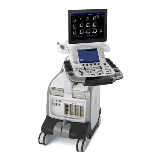
VIVID E9 overview 5-3-1 Purpose of this section The purpose of this section is to give you an overview of VIVID E9 and how it function. 5-3-2 Introduction The VIVID E9 ultrasound unit is a high performance digital ultrasound imaging system with total data management. -
Page 200: Vivid E9 General Description
5-3-3 VIVID E9 general description VIVID E9 is a digital beamforming system. Signal flow travels from the Probe Connector Panel to the Front End Electronics, then to the Back End Processor, and finally, the results are displayed on the monitor. -
Page 201: Signal Flow Overview
GE H EALTHCARE GA091568, R VIVID E9 S IRECTION EVISION ERVICE ANUAL 5-3-5 Signal flow overview The GTX board(s) in the Front End Processor, generates the strong bursts transmitted by the probes as ultrasound, into the body. The Transmit bursts are routed from the GTX board via the XD bus to the Relay board where the ultrasound probes are connected. -
Page 202: System Configuration And Software
At power up, all necessary software is loaded from the hard disk drive. 5-3-7 The electronics VIVID E9 internal electronics are divided into two card cages: • Front End Processor (FEP) The FEP is sometimes called “Front End Card Cage”, “Front End”, or only “Card Cage”. -
Page 203: Vivid E9 Interconnection Diagram
GE H EALTHCARE GA091568, R VIVID E9 S IRECTION EVISION ERVICE ANUAL 5-3-8 VIVID E9 interconnection diagram Figure 5-5 VIVID E9 w/ BEP6 interconnection diagram Chapter 5 - Components and functions (theory) 5 - 13... - Page 204 GE H EALTHCARE GA091568, R VIVID E9 S IRECTION EVISION ERVICE ANUAL 5-3-8 VIVID E9 interconnection diagram (cont’d) Figure 5-6 VIVID E9 w/ BEP5 interconnection diagram 5 - 14 Section 5-3 - VIVID E9 overview...
-
Page 205: Vivid E9'S Operating Modes
VIVID E9`s high performance Octave Imaging provides superb detail resolution and penetration, outstanding contrast resolution, excellent acoustic clutter rejection and an easy to operate user interface for switching into Octave Imaging mode. - Page 206 4D Imaging • Real-time, non-gated 4D imaging The 4D probes on the Vivid E9 enables real-time, non-gated 4D tissue and color imaging. The volume data is displayed in real-time with volume rendering techniques for visualization of valves and structures. •...
-
Page 207: Top Console With Lcd Monitor And Operator Panel
Doppler scanning/replay 5-4-1-2 Connection between the Top Console and the rest of the VIVID E9 A flexible harness of electrical wires secures the connection between the Top Console and the rest of the VIVID E9. - Page 208 VIVID E9 S IRECTION EVISION ERVICE ANUAL 5-4-1-3 The XYZ mechanism The Top Console can be adjusted without moving the complete VIVID E9 console. It can be moved; • up/down (Z-axis) • sideways to the left and to the right (X-axis) •...
- Page 209 The XY (frogleg) brakes will stay ON if the VIVID E9 is powered down when the Operator Panel is locked. This enables release of the Park Lock, initiated by the micro switches on the Front Handle of the Operator Panel.
- Page 210 GE H EALTHCARE GA091568, R VIVID E9 S IRECTION EVISION ERVICE ANUAL 5-4-1-5 Top Console block diagram Figure 5-9 Top Console block diagram MAIN CABLE TO/FROM MAIN CONSOLE Cable List: MAIN CABLE DVI VIDEO 48V POWER/AUDIO Cable Part Number Description...
-
Page 211: Operator Panel (Control Panel)
GE H EALTHCARE GA091568, R VIVID E9 S IRECTION EVISION ERVICE ANUAL 5-4-2 Operator Panel (Control Panel) 5-4-2-1 Operator Panel general description The Operator Panel includes an On/Off switch, different controls for manipulating the picture quality, and controls for use in Measure & Analyze (M&A). - Page 212 5-4-2-2 Operator Panel block diagram The VIVID E9 Operator Panel is a complex user interaction device with several sub devices. This includes a trackball with buttons, an alphanumeric keyboard, a custom keyboard, and a touch panel overlay. See the diagram below for a simplified view of how these devices are interconnected.
- Page 213 GE H EALTHCARE GA091568, R VIVID E9 S IRECTION EVISION ERVICE ANUAL Figure 5-12 Top Console (with Operator Panel) block diagram TO/FROM MAIN CONSOLE MAIN CABLE DVI VIDEO 48V POWER/AUDIO USB FOR OP PANEL USB FOR VIDEO ON TOUCH PANEL...
-
Page 214: Main Console
GE H EALTHCARE GA091568, R VIVID E9 S IRECTION EVISION ERVICE ANUAL Section 5-5 Main Console 5-5-1 Main Console description Figure 5-13 Main Console MAIN CONSOLE The Main Console hosts the: • Patient I/O • Front End Processor (FEP) •... -
Page 215: Air Flow Control
If the VIVID E9 power down due to high temperature inside the unit, it may indicate that the air filters need to be dusted or a failure situation. -
Page 216: Casters And Brakes
ERVICE ANUAL Section 5-7 Casters and Brakes The VIVID E9 has four casters (wheels), the Front Casters and the Rear Casters. • All Casters are mounted on swivels so they can change direction as needed. • Additional, the Front Casters can be locked in fixed directions. -
Page 217: Front End Processor (Fep)
NOTICE change the color-keys position. Don’t insert a card in the wrong position in the Card Rack. If the power is turned on with a card placed in the wrong position, the VIVID E9 will be destroyed. 5-8-1-1 Front End Processor cards overview... - Page 218 GE H EALTHCARE GA091568, R VIVID E9 S IRECTION EVISION ERVICE ANUAL 5-8-1-2 FEP’s Location in the Unit The FEP is located on the right side of the system, behind the Right Side Cover. 5-8-1-3 Input DC voltages These voltages comes from the Main Power Supply.
-
Page 219: Transmitter And Receiver Subsystem
Plane to a separate connector, then via a cable to the Doppler probe connector on the front of VIVID E9. In the Doppler probe, the signal is connected to one of the two probe elements. Chapter 5 - Components and functions (theory) - Page 220 FE_BUS STA_BUS NOTE: The number of cards depend on the VIVID E9 model, and options installed. • The reflected signal from body structures and blood cells are routed from the probe, via the Relay Board and the Front Plane to the GRX (receiver) boards, where pre-amplification and Analog Time Gain Compensation (ATGC) is performed.
- Page 221 FE_BUS STA_BUS NOTE: The number of cards depend on the VIVID E9 model, and options installed. • The Global Radio Frequency Interface (GFI) board controls the GTX (transmitter) and GRX / DRX (analog and digital receiver boards). GFI loads all parameters to the GTX and DRX ASICs. It reads the probe identification, selects probe connector on Relay board and controls the high voltage multiplexer in linear probes.
-
Page 222: Transmitter Board (Gtx)
GTX-TLP192 with 192 channels per card (Introduced August 2011) GTX-TLP 3.0 The GTX-TLP 3.0 contains 64 individually controlled transmit channels. In VIVID E9, either three or four boards are used, giving a total of 192 or 256 TX channels. •... - Page 223 GE H EALTHCARE GA091568, R VIVID E9 S IRECTION EVISION ERVICE ANUAL 5-8-3-1 General description (cont’d) Figure 5-18 Block Diagram for the GTX board (one channel illustrated) TSV1&2 FROM TSV1P MAIN POWER SUPPLY TSV2P TSV2N TSV1N TX_TRIG_L FROM GFI FE_BUS...
- Page 224 • VIVID E9 BT’09 uses three GTX TLP 3.0 boards, ref. Figure 5-20. • VIVID E9 BT’11 uses either three GTX TLP 3.0 boards, ref. Figure 5-20, or one GTX-TLP192 board, ref. Figure 5-21. NOTE: If the GTX-TLP192 card is used, only one TX card is required.
- Page 225 GE H EALTHCARE GA091568, R VIVID E9 S IRECTION EVISION ERVICE ANUAL 5-8-3-2 Location in the Unit (cont’d) Figure 5-21 GTX TLP-192 board location - 192 TX channels (introduced 2011) CW PROBE CONNECTOR OPTIONAL DC VOLTAGES TX (PULSER) VOLTAGES GFI AUDIO...
- Page 226 GE H EALTHCARE GA091568, R VIVID E9 S IRECTION EVISION ERVICE ANUAL 5-8-3-6 LEDs on the GTX-192 board Figure 5-22 LEDs on GTX-192 R24_34 R8_33 R9_33 R24_33 R25_34 R25_33 D6_34 D3_33 D6_33 R21_34 R5_33 R21_33 FL18 R22_34 Q2_34 U2_34 R6_33...
- Page 227 GE H EALTHCARE GA091568, R VIVID E9 S IRECTION EVISION ERVICE ANUAL 5-8-3-7 LEDs on the GTX-64 board Figure 5-23 LEDs DS19 DS19 DS17 DS17 DS18 DS18 Table 5-6 LEDs on the GTX-64 board LED NO. COLOR DESCRIPTION NORMAL OPERATION...
-
Page 228: Relay Board (Rly)
1 - PD PROBE PORT: FOR VIVID 7 COMPATIBLE PROBE CONNECTORS 2 - PDT PROBE PORTS: FOR VIVID E9 SPECIFIC PROBE CONNECTORS The signals to the Doppler probe are routed via the FEP Backplane and cables to the Doppler probe connector. - Page 229 GE H EALTHCARE GA091568, R VIVID E9 S IRECTION EVISION ERVICE ANUAL 5-8-4-2 Location in the Unit The Relay board is located in the Front End Rack on the end nearest to the front of the scanner. 5-8-4-3 Input DC Voltages: •...
- Page 230 GE H EALTHCARE GA091568, R VIVID E9 S IRECTION EVISION ERVICE ANUAL 5-8-4-6 LEDs Figure 5-26 LEDs on the Relay board DS11 DS12 4 5 6 7 8 9 DS10 Table 5-7 LEDs on the Relay board LED NO. COLOR...
-
Page 231: Receiver Board (Grx)
GE H EALTHCARE GA091568, R VIVID E9 S IRECTION EVISION ERVICE ANUAL 5-8-5 Receiver Board (GRX) 5-8-5-1 General description Figure 5-27 GRX board The analog Receiver boards (GRX) receives the weak ultrasound echo signals from the probes, via the Relay board and the XD bus on the Front Plane boards. The main task for the GRX boards are to do Time Variable Amplification on the echo signals. - Page 232 GE H EALTHCARE GA091568, R VIVID E9 S IRECTION EVISION ERVICE ANUAL 5-8-5-2 Location in the Unit Figure 5-28 GRX location 2 pc GRX boards 5-8-5-3 Input DC Voltages • +6 VDC • -5 VDC • +15 VDC • -15 VDC...
-
Page 233: Front Plane Boards (Xd Bus)
• The first model (B), supporting up to four TX cards with 64 channels each, was used from the introduction of VIVID E9. • In August 2011, a new Front Plane board model (A), supporting the TX card with 192 TX channels, was phased into production. -
Page 234: Digital Receiver Board (Drx)
Today we are using three DRX boards to support 192 receiver channels. 5-8-7-2 Location in the Unit Figure 5-30 DRX location Up to 4 pc DRX boards (VIVID E9 is using three DRX boards). 5 - 44 Section 5-8 - Front End Processor (FEP) - Page 235 GE H EALTHCARE GA091568, R VIVID E9 S IRECTION EVISION ERVICE ANUAL 5-8-7-3 Input DC Voltages +24 VDC. Other voltages are generated locally on the GRX: • • • 2V5_MGT_Tx • 1V8 (one for each Nathan column in use) •...
- Page 236 GE H EALTHCARE GA091568, R VIVID E9 S IRECTION EVISION ERVICE ANUAL 5-8-7-7 LEDs on the DRX board - the GDIF status display Programming status LEDs exist on the left side of the board. They indicate the programming status of the GDIF FPGA.
-
Page 237: Front End Interface Board (Gfi)
GE H EALTHCARE GA091568, R VIVID E9 S IRECTION EVISION ERVICE ANUAL 5-8-8 Front End Interface Board (GFI) 5-8-8-1 General description Figure 5-33 GFI2 board The GFI is the Front End Processor’s (FEP’s) interface to the Back End Processor (BEP). - Page 238 GE H EALTHCARE GA091568, R VIVID E9 S IRECTION EVISION ERVICE ANUAL 5-8-8-2 Location in the Unit The GFI2 board is plugged into the Back Plane as the right most board in the FE rack. Figure 5-34 GFI2 location GFI2 BOARD...
- Page 239 GE H EALTHCARE GA091568, R VIVID E9 S IRECTION EVISION ERVICE ANUAL 5-8-8-5 Outputs • PCI Express bus to BEP (connector J14 on the card) • STA bus • Other Control signals like TXTRIG etc. 5-8-8-6 LEDs on the GFI board...
-
Page 240: Fep Backplane
GE H EALTHCARE GA091568, R VIVID E9 S IRECTION EVISION ERVICE ANUAL 5-8-9 FEP Backplane 5-8-9-1 General description Figure 5-35 FEP Backplane Front side of the FEP Backplane Rear side of the FEP Backplane 1. CW Doppler Connector 2. Power Connectors 2. - Page 241 GE H EALTHCARE GA091568, R VIVID E9 S IRECTION EVISION ERVICE ANUAL 5-8-9-2 Location in the unit The FEP Backplane is attached to the rear side of the Front End Card Rack. Figure 5-36 FEP Backplane location FEP BACKPLANE Chapter 5 - Components and functions (theory)
-
Page 242: Back End Processor (Bep)
This chapter includes descriptions for the vital BEP modules. 5-9-2 Introduction The Back End Processor is a computer, designed specially for the use in the VIVID E9 ultrasound scanners made by GE. The following BEP models have been used for VIVID E9: •... -
Page 243: Location Of The Back End Processor (Bep)
GE H EALTHCARE GA091568, R VIVID E9 S IRECTION EVISION ERVICE ANUAL 5-9-4 Location of the Back End Processor (BEP) The BEP is located on the left side, inside the scanner, see Figure 5-37. Figure 5-37 Back End Processor THE BEP IS LOCATED BEHIND... -
Page 244: Cpu/Back End Processor (Bep) - Block Diagram
Brake Commands VOLTAGE FROM POWER SUPPLY NOTE: ON VIVID E9 WITHOUT DVR, THE SHORT CABLE BETWEEN THE GRAPHICS BOARD AND THE DVR IS MISSING, AND THE DVI OUT CABLE FOR THE IO BOARD IS CONNECTED TO THE VIDEO CARD. 5 - 54... -
Page 245: Bep Description
GE H EALTHCARE GA091568, R VIVID E9 S IRECTION EVISION ERVICE ANUAL 5-9-6 BEP description 5-9-6-1 The EMC Enclosure House • A power supply for local voltages • A motherboard with RAM, a processor and PCI connectors for extension cards •... -
Page 246: Bep6 Face, Top And Rear Connections
4: 48V 8: 12V 9: 5V 10: AC_FAIL_N 11: 3.3V 12: 5V_STDBY 16: Not Used on Vivid E9 24: PWR_SW 25: PSON_N J100 - OP Panel Video (USB) J7 - OP Panel Buttons (USB) J28 - XYZ Motor (USB) J27 - Spare (USB) - Page 247 GE H EALTHCARE GA091568, R VIVID E9 S IRECTION EVISION ERVICE ANUAL 5-9-7 BEP6 Face, Top and Rear connections (cont’d) Table 5-10 BEP6 Top connections ITEM DESCRIPTION ILLUSTRATION J1 - Main PS 48V, 5V In J5 - Front End Rack (PCIe to GFI)
-
Page 248: Bep5 Face And Top Connections
GE H EALTHCARE GA091568, R VIVID E9 S IRECTION EVISION ERVICE ANUAL 5-9-8 BEP5 Face and Top connections Please refer to the illustrations. Figure 5-41 BEP5 Face connections (Sub-woofer) Figure 5-42 BEP5 Top connections USB to USB to Main PS... - Page 249 ANUAL 5-9-8-1 USB distribution USB is used to communicate with, and/or control, many functions and devices in the VIVID E9. The illustration below shows how the USB signals are distributed in BEP6. Figure 5-43 USB distribution in BEP6 The illustration below shows how the USB signals are distributed in BEP5.
- Page 250 GE H EALTHCARE GA091568, R VIVID E9 S IRECTION EVISION ERVICE ANUAL 5-9-8-2 SATA distribution - BEP6 Figure 5-45 BEP6 - SATA distribution 5 - 60 Section 5-9 - Back End Processor (BEP)
- Page 251 GE H EALTHCARE GA091568, R VIVID E9 S IRECTION EVISION ERVICE ANUAL 5-9-8-3 Use of Expansion Slots on BEP6 Motherboard Use of Expansion Slots, listed from the rightmost slot: • BEP 6.0 Power Board Assembly • Graphics Adapter (Video Card) •...
- Page 252 GE H EALTHCARE GA091568, R VIVID E9 S IRECTION EVISION ERVICE ANUAL 5-9-8-4 Use of Expansion Slots on BEP5 Motherboard Use of Expansion Slots, listed from the rightmost slot: • DVR Board (Optional) • Graphics Adapter (Video Card) 5-9-8-5 BIOS Beep Codes BIOS uses beeps of varying duration.
-
Page 253: Input Dc Voltages
GE H EALTHCARE GA091568, R VIVID E9 S IRECTION EVISION ERVICE ANUAL 5-9-9 Input DC Voltages NOTE: The BEP is not connected to AC power. The BEP gets it power supply via the BEP Power Supply. Chapter 5 - Components and functions (theory) -
Page 254: Input Signals
GE H EALTHCARE GA091568, R VIVID E9 S IRECTION EVISION ERVICE ANUAL 5-9-10 Input Signals BEP6: • Audio signal path: GFI > FEP Backplane > BEP6 MBD > [a and b] a: > IO Board > Audio Out b: > DVR... -
Page 255: Bi-Directional Signals
GE H EALTHCARE GA091568, R VIVID E9 S IRECTION EVISION ERVICE ANUAL 5-9-11 Bi-directional signals BEP6: Table 5-13 BEP6 Bi-directional Signals Signal Name Description Signal Path IPASS2 (BEP MBD) > Cable N (inside PCIe PCI Express BEP) > J5 (BEP) > PCI Express Cable >... -
Page 256: Leds
GE H EALTHCARE GA091568, R VIVID E9 S IRECTION EVISION ERVICE ANUAL 5-9-13 LEDs 5-9-13-1 LEDs on the BEP5/BEP6 Front Figure 5-47 Front Panel Table 5-16 LEDs on the BEP’s front ITEM LED NAME DESCRIPTION HD ACTIVITY ACT LED Blinks when the Hard Disk drive is active... - Page 257 GE H EALTHCARE GA091568, R VIVID E9 S IRECTION EVISION ERVICE ANUAL 5-9-13-2 LEDs on the BEP6’s Front Cover Table 5-17 LEDs on the BEP6’s Front Cover DESCRIPTION ILLUSTRATION The LEDs for the BEP6’s Power Supply can be viewed without removing the BEP6’s Front Cover...
- Page 258 GE H EALTHCARE GA091568, R VIVID E9 S IRECTION EVISION ERVICE ANUAL 5-9-13-3 LEDs on the BEP5’s face Figure 5-48 LEDs on the BEP5’s face Table 5-18 LEDs below DVI connector LED NAME DESCRIPTION ERROR Conditions Green LED indicates that there is video output...
-
Page 259: Bep Power Supply
GE Custom Power Supply Board (for the first BEP5 models) NOTE: The BEP Power Supply does not handle AC voltages. The BEP Power Supply receives its input DC voltage from the VIVID E9’s Main Power Supply. Dedicated control signals, are used for controlling the BEP Power Supply. 5-9-14-2... - Page 260 GE H EALTHCARE GA091568, R VIVID E9 S IRECTION EVISION ERVICE ANUAL 5-9-14-3 BEP5 Power Supply Block Diagram Figure 5-49 BEP5 Power Supply Block Diagram MAIN POWER SUPPLY HDD (SATA POWER) BEP MOTHERBOARD TO PATIENT I/O TO I/O BOARD 5-9-14-4...
- Page 261 GE H EALTHCARE GA091568, R VIVID E9 S IRECTION EVISION ERVICE ANUAL 5-9-14-5 Location in the BEP5 The BEP Power Supply is located inside, at the top of the BEP5. Figure 5-51 BEP5 Power Supply Location BEP5 POWER SUPPLY 5-9-14-6 Input Voltage (BEP6 / BEP5) +48 VDC from the Main Power Supply.
- Page 262 GE H EALTHCARE GA091568, R VIVID E9 S IRECTION EVISION ERVICE ANUAL 5-9-14-9 Output Voltages • +48V • +12V • • +3.3V • +5Vstby 5-9-14-10 LEDs on BEP6 Power Supply Nine LEDs on the BEP6 Power Supply can be viewed through holes in the BEP6 Front Cover.
- Page 263 GE H EALTHCARE GA091568, R VIVID E9 S IRECTION EVISION ERVICE ANUAL 5-9-14-12 Test Points on BEP5 Power Supply Several Test Points are available through cut-outs in the BEP Power supply. Be careful so you don’t short-circuit the signals when placing the test probe(s).
-
Page 264: Io Board
(BEP5 I/O ONLY) Boundary Scan from the BEP to boards in the Front End Card Rack 5-9-15-2 Location in the unit At the rear of the BEP with the Rear panel available at the rear of the VIVID E9. 5-9-15-3 Input DC voltages Internal in BEP from the BEP Power Supply. - Page 265 GE H EALTHCARE GA091568, R VIVID E9 S IRECTION EVISION ERVICE ANUAL 5-9-15-4 LEDs on the BEP5 Rear Panel Figure 5-54 LEDs on the BEP5 Rear Panel 5180173 rev1 Two LEDs are located to the right for each USB connector.
-
Page 266: Graphics Adapter
SATA (Serial ATA) Hard Disk Drive (HDD) inside the Back End Processor cabinet (size: 160 GB, or more) • CD/DVD drive available from front of VIVID E9. ONLY CD-R discs and DVD-R recordable discs are supported. • The optional DVR uses DVD+RW discs. -
Page 267: Power Distribution
ANUAL Section 5-10 Power distribution 5-10-1 Purpose of this section The power distribution within the VIVID E9 is described in this section. 5-10-2 Main Power Supply 5-10-2-1 General description The Main Power Supply’s main task is to galvanically isolate the scanner from the on-site Mains Power System and to supply the various internal subsystems with AC or DC power. - Page 268 GE H EALTHCARE GA091568, R VIVID E9 S IRECTION EVISION ERVICE ANUAL 5-10-2-1 General description (cont’d) Power from the wall outlet (100 VAC to 230 VAC, 50/60 Hz) is connected to the Main Power Supply. Figure 5-56 Main Power Supply block diagram 0$,1 32:(5 6833/<...
- Page 269 GE H EALTHCARE GA091568, R VIVID E9 S IRECTION EVISION ERVICE ANUAL 5-10-2-1 General description (cont’d) The mains cord has plugs in both ends. A female plug connects to the scanner and a male plug to the wall outlet. Figure 5-57 Main Power Supply...
- Page 270 GE H EALTHCARE GA091568, R VIVID E9 S IRECTION EVISION ERVICE ANUAL 5-10-2-4 Bidirectional Signals USB bus Table 5-23 USB connector DESCRIPTION COMMENTS Originates on the BEP. The USB is used to set the power supply to the correct transmit (XD) voltages.
- Page 271 GE H EALTHCARE GA091568, R VIVID E9 S IRECTION EVISION ERVICE ANUAL Table 5-24 Power outputs (cont’d) sheet 2 of 2 CONNECTOR DESCRIPTION COMMENTS +48 VDC BACK END PROCESSOR AND MOTOR POWER - The ‘48V_OK’ indicates that the 48 VDC measured on the BEP, is OK.
-
Page 272: Power Up Sequence Description
Overview The Power Up Sequence can be divided in the following steps: 1.) Connect the mains power to the VIVID E9 and switch AC Breaker to ON position. 2.) Press the ON button on the Operator Panel. 3.) BEP (and system) power-up. - Page 273 GE H EALTHCARE GA091568, R VIVID E9 S IRECTION EVISION ERVICE ANUAL 5-10-3-2 AC Breaker to ON position (cont’d) • The 5Vstdby LED is lit (green). Figure 5-60 LEDs on BEP6 Power Supply (standby) Figure 5-61 LEDs on BEP5 Power Supply (standby) •...
- Page 274 GE H EALTHCARE GA091568, R VIVID E9 S IRECTION EVISION ERVICE ANUAL 5-10-3-3 The ON/OFF button on the Operator Panel has been pressed When the ON/OFF switch is depressed, the BEP power is delivered to the different parts of the system...
- Page 275 GE H EALTHCARE GA091568, R VIVID E9 S IRECTION EVISION ERVICE ANUAL 5-10-3-3 The ON/OFF button on the Operator Panel has been pressed (cont’d) • Power to the BEP is turned on, so it can start to boot. Figure 5-63 LEDs on BEP6 Power Supply (powered) Figure 5-64 LEDs on BEP Power Supply (powered) •...
-
Page 276: Power Down Sequence Description
GE H EALTHCARE GA091568, R VIVID E9 S IRECTION EVISION ERVICE ANUAL 5-10-4 Power Down Sequence description 5-10-4-1 Overview There are three possible scenarios for Power Down of the unit: • Power Down • Forced Power Down • Power Loss Each of the scenarios are described below. - Page 277 GE H EALTHCARE GA091568, R VIVID E9 S IRECTION EVISION ERVICE ANUAL 5-10-4-3 Forced Power Down NOTE: In case of total lockup of the system, hold the ON/OFF button down a few seconds to turn the system off. Forced Power Down is initiated by depressing the ON/OFF button on the keyboard for a few seconds, until the power down sequence starts: 1.) BEP detects long-term contact of Power (ON/OFF) switch.
-
Page 278: Input And Output (I/O) Modules
This input is intended as a tool for easier synchronization of images and cineloop control during ultrasound examinations. The Patient I/O panel is located on the front of VIVID E9. Figure 5-65 Patient I/O Panel 1 - PHONO... - Page 279 GE H EALTHCARE GA091568, R VIVID E9 S IRECTION EVISION ERVICE ANUAL 5-11-2-1 General description (cont’d) The three inputs are separately isolated due to safety requirements. The module extracts respiration from ECG signals from the ECG/Respiration input. The scanned image that is displayed, is synchronized with the ECG, respiration and phono traces. In M-Mode or Doppler, the traces are synchronized to that particular mode's sweep.
- Page 280 GE H EALTHCARE GA091568, R VIVID E9 S IRECTION EVISION ERVICE ANUAL 5-11-2-3 Input DC Voltages +5 VDC +12 VDC Pinout for the DC input on the Patient I/O module Table 5-25 DC input pinout on the Patient I/O Module...
- Page 281 GE H EALTHCARE GA091568, R VIVID E9 S IRECTION EVISION ERVICE ANUAL 5-11-2-5 Patient I/O - outputs USB2: • Digital Trace Data • Module ID PROM communication Pinout for the USB outlet on the Patient I/O module Table 5-27 USB outlet on the Patient I/O Module...
-
Page 282: Bep6 I/O Board
GE H EALTHCARE GA091568, R VIVID E9 S IRECTION EVISION ERVICE ANUAL 5-11-3 BEP6 I/O Board 5-11-3-1 General description BEP6’s I/O board is the interface between the BEP and the rest of the system. It distrbutes USB to the Rear IO, the OP and to internal units (printer and Patient IO). It distributes SATA to the DVD(s). It splits video between the main monitor and rear video output. - Page 283 GE H EALTHCARE GA091568, R VIVID E9 S IRECTION EVISION ERVICE ANUAL 5-11-3-2 Location in the Unit The I/O board is located inside the BEP with some connectors available on the rear of the system. 5-11-3-3 Input signals • Supply voltage of 5V and 12V from BEP (and BEP Power Card).
-
Page 284: Bep5 I/O Board
GE H EALTHCARE GA091568, R VIVID E9 S IRECTION EVISION ERVICE ANUAL 5-11-4 BEP5 I/O Board 5-11-4-1 General description The I/O board is the interface between the BEP and the rest of the system. It contains three USB hubs, and it splits video between the main monitor and rear video output. It also distributes audio to speakers and rear connectors. -
Page 285: Probe Connectors
GE H EALTHCARE GA091568, R VIVID E9 S IRECTION EVISION ERVICE ANUAL 5-11-4-3 Input signals • Supply voltage of 5V and 12V from BEP power supply card. The power voltages are regulated at +/-10%. • 5V STDBY from the BEP power supply card for OPIO (Pass through). -
Page 286: Peripherals Overview
This is a kit with a Video Recorder Card inside the BEP and a DVD R/W unit used for export of the recorded video. The DVD R/W unit is available from the front of the VIVID E9. NOTE: The DVD drive used for video recording, supports DVD+R/W. -
Page 287: External Peripherals
• USB Memory Key 2GB Trancend (USB2-0) • The following USB Flash Cards, approved for Vivid 7, may also be used on the VIVID E9, but are not available for sale anymore: Kingston DataTraveler Elite 256 MB Sandisk Cruzer Micro 256 MB... - Page 288 The Iomega Ultramax desktop hard drive is an external desktop hard drive, connected via USB to either a Vivid E9 or an EchoPAC PC workstation. It is configured as RAID 1, so the content is mirrored on two hard disk drives. Due to the RAID 1 mirroring, the unit can store maximum 1 TB of data.
-
Page 289: Product Manuals
VIVID E9 S IRECTION EVISION ERVICE ANUAL Section 5-13 Product manuals The information needed to use and service the VIVID E9 scanner is collected in the documents described in this section. 5-13-1 User documentation • VIVID E9 User Manual/User Guide •... -
Page 290: Common Service Desktop Overview
Common Service Desktop overview 5-14-1 Purpose of this section In this section, the Common Service Desktop, as implemented on the VIVID E9, is described. 5-14-2 Introduction The Service Platform contains a set of software modules that are common to all ultrasound and cardiology systems containing a PC backend. -
Page 291: Global Service User Interface (Gsui)
Global Service User Interface (GSUI) 5-14-4-1 Internationalization The user interface provided by the service platform is designed for GE personnel and as such is in English only. There is no multi-lingual capability built into the Service Interface. 5-14-4-2 Service Login Select the phone icon in the status bar at the bottom of the scan display screen. -
Page 292: Restart Vivid E9 After Diagnostics
Every access request, whether successful or not, will be logged into a service access log that is viewable to authorized users. Section 5-15 Restart VIVID E9 after diagnostics Always shutdown the system and reboot after a diagnostics session. 5 - 102... -
Page 293: Overview
Overview 6-1-1 Purpose of this chapter This chapter describes how to adjustments the VIVID E9. 6-1-2 Contents in this chapter Overview............. 6-1 LCD Monitor adjustments . -
Page 294: Lcd Monitor Adjustments
The LCD settings have been optimized at the factory, so normally, there should be no need for any further adjustments. Default Brightness for the 19” LCD screen on VIVID E9 is: 89%. Under special light conditions, you may want to adjust the LCD screen’s Brightness. -
Page 295: Advanced Lcd Adjustments
GE H EALTHCARE GA091568, R VIVID E9 S IRECTION EVISION ERVICE ANUAL 6-2-5 Advanced LCD adjustments NOTE: Do not adjust these settings unless necessary! To get access to the advanced adjustments, press the Mode button for more than 10 seconds. This will display the Advanced Menu on the screen. -
Page 296: Test The Lcd Arm And Lcd Monitor Range Of Motion
GE H EALTHCARE GA091568, R VIVID E9 S IRECTION EVISION ERVICE ANUAL Section 6-3 Test the LCD Arm and LCD Monitor range of motion NOTE: This procedure is valid for both the 17 inch and the 19 inch LCD monitors. -
Page 297: Backlight Adjustment
GE H EALTHCARE GA091568, R VIVID E9 S IRECTION EVISION ERVICE ANUAL Section 6-4 Backlight adjustment 6-4-1 Purpose of this section This section describes how to adjust the backlight on the 17” LCD monitor. 6-4-2 Cautions and Warnings 6-4-3 Accessing the Main LCD and Touch Screen Backlight Adjustments 1.) Select Utility on the Touch Screen. -
Page 298: Backlight And Blue Tint Adjustment
GE H EALTHCARE GA091568, R VIVID E9 S IRECTION EVISION ERVICE ANUAL 6-4-4 Backlight and Blue Tint Adjustment On the Utility screen - Page 1 of 2, you can adjust the Backlight and the Blue tint on the Main LCD screen and the Backlight on the Touch Panel (TP). -
Page 299: Test Images
GE H EALTHCARE GA091568, R VIVID E9 S IRECTION EVISION ERVICE ANUAL 6-4-6 Test Images Select Page 2 of 2 on the Utility screen. Figure 6-8 Select Test Image • Turn the second rotary from the left side, to select between the Test Images. The Test Images are reproduced in Table 6-2. - Page 300 GE H EALTHCARE GA091568, R VIVID E9 S IRECTION EVISION ERVICE ANUAL Table 6-2 Test Images (cont’d) sheet 2 of 3 TEST IMAGE No. TEST IMAGES DESCRIPTION Test - Green grades Test - Blue grades Blue Circle on Black background...
- Page 301 GE H EALTHCARE GA091568, R VIVID E9 S IRECTION EVISION ERVICE ANUAL Table 6-2 Test Images (cont’d) sheet 3 of 3 TEST IMAGE No. TEST IMAGES DESCRIPTION White Straight Line Chapter 6 - Service adjustments 6 - 9...
-
Page 302: Touch Screen Calibration
GE H EALTHCARE GA091568, R VIVID E9 S IRECTION EVISION ERVICE ANUAL Section 6-5 Touch Screen Calibration The Touch Screen Calibration is found on the Operator Panel Test Dialog. Follow these steps to open the Operator Panel Test Dialog: 1.) Select Config (F2). -
Page 303: Dc Offset Calibration (Front End Alignment)
1.) Disconnect all probes. 2.) Power on the VIVID E9. 3.) Select the InSite ExC icon (GE phone icon) on the screen to display the InSite ExC menu. Figure 6-10 InSite ExC icon in the status bar 4.) Select Service Desktop. -
Page 304: Adjusting The Xyz Mechanism
GE H EALTHCARE GA091568, R VIVID E9 S IRECTION EVISION ERVICE ANUAL Section 6-7 Adjusting the XYZ Mechanism 6-7-1 Operator Panel XY movement - principle of operation When the OP is in the locked position, press the left button ”lock” of the Frogleg Controls, which causes the motorized park lock to release and releases the brakes, momentarily in the froglegs. -
Page 305: Adjusting The Xy Lock
GE H EALTHCARE GA091568, R VIVID E9 S IRECTION EVISION ERVICE ANUAL 6-7-2 Adjusting the XY Lock Use a 3 mm hex tool to adjust the XY Lock release for optimal lock and minimal slack in transport mode. • Rotating the screw clockwise will tighten the Lock and will reduce slack, but will also require more force for engaging the Lock. -
Page 306: Xy Manual Release For Lock And Brake Mechanism And Adjustment
GE H EALTHCARE GA091568, R VIVID E9 S IRECTION EVISION ERVICE ANUAL 6-7-3 XY Manual Release for Lock and Brake Mechanism and Adjustment The following procedure is intended to release and adjust the XY mechanism. 6-7-3-1 XY Lock and Brake Mechanism Parts Figure 6-13 XY Lock and Brake Mechanism Parts 1.) U-bolt... - Page 307 GE H EALTHCARE GA091568, R VIVID E9 S IRECTION EVISION ERVICE ANUAL 6-7-3-2 XY Lock Adjustment for Lock and Brake Mechanism Follow this procedure if the park lock is not working, or the lock does not respond when pressing the Frogleg Controls: 1.) Release the lock manually.
- Page 308 GE H EALTHCARE GA091568, R VIVID E9 S IRECTION EVISION ERVICE ANUAL 6-7-3-2 XY Lock Adjustment for Lock and Brake Mechanism (cont’d) • If the Park Lock Nut (2) and the Park Lock Lever (3), are in the positions illustrated in Figure 6- 15, the lock will not engage.
-
Page 309: Using The Park Lock Properly
GE H EALTHCARE GA091568, R VIVID E9 S IRECTION EVISION ERVICE ANUAL 6-7-3-2 XY Lock Adjustment for Lock and Brake Mechanism (cont’d) • Before reassembling the Lock Assembly, make sure the Park Lock Nut (2) and the Park Lock Lever (3) are in the position illustrated in Figure 6-17. - Page 310 GE H EALTHCARE GA091568, R VIVID E9 S IRECTION EVISION ERVICE ANUAL This page left blank to facilitate double-sided printing. 6 - 18 Section 6-7 - Adjusting the XYZ Mechanism...
-
Page 311: Overview
GE H EALTHCARE GA091568, R VIVID E9 S IRECTION EVISION ERVICE ANUAL Chapter 7 Diagnostics / troubleshooting Section 7-1 Overview 7-1-1 Purpose of this chapter This chapter describes how to setup and run the tools and software that help maintain image quality and system operation. -
Page 312: Service Safety Considerations
The system starts the shutdown sequence at 90 degrees centigrade (90 ºC). • New in v112.0: There is a new reminder showing “Clean air filter”. It is displayed at start-up of the VIVID E9, and is repeated at specific pre-defined intervals. 7-3-2 Reset the BEP from a Hang Question: It seems that the BEP is “hanging”... -
Page 313: How To Release The Top Console When Power Is Unavailable
GE H EALTHCARE GA091568, R VIVID E9 S IRECTION EVISION ERVICE ANUAL 7-3-3 How to Release the Top Console when power is unavailable Question: How to release the Z brakes (Up/Down) when without power? Answer: There is a lever behind the openings in the Rear Cover. Press the lever to the right to release the X/Y brakes. -
Page 314: Troubleshooting Tips
IRECTION EVISION ERVICE ANUAL Section 7-4 Troubleshooting Tips 7-4-1 Shortcut Keys This is a list of useful shortcuts for use during VIVID E9 service. Table 7-1 Shortcuts SHORTCUT DESCRIPTION Alt+B BOOKMARK. PLACE A BOOKMARK IN LOGS. SYSTEM PROBLEM REPORTING. See: 7-6-2 "Collect a Trouble Image with Logs"... -
Page 315: Image Artifacts Caused By Front End Boards
GE H EALTHCARE GA091568, R VIVID E9 S IRECTION EVISION ERVICE ANUAL 7-4-2 Image Artifacts Caused by Front End Boards Image artifacts can be caused by any of the boards on the Front End. Artifacts may be caused by the power supply or board failures. -
Page 316: Back End Processor
GE H EALTHCARE GA091568, R VIVID E9 S IRECTION EVISION ERVICE ANUAL 7-4-3 Back End Processor 7-4-3-1 System Halt Errors - Lock ups or Intermittent Problems • Collect Error Logs and send them to the OLC to be evaluated. (On the scan screen, press ALT+D). -
Page 317: Operator Panel
GE H EALTHCARE GA091568, R VIVID E9 S IRECTION EVISION ERVICE ANUAL 7-4-4 Operator Panel 7-4-4-1 No Audio • Check volume settings in the application and also in Windows. • Use headphones, (the type that you use on a personal CD player or a laptop) to test the audio output directly from the back of the BEP. -
Page 318: Network Connectivity Troubleshooting
If the status reports No network, verify cabling. 7-5-2 Cannot connect to anything via the network • Check with your laptop if you can ping the VIVID E9 and the device (Printer or PACs). 7 - 8 Section 7-5 - Network Connectivity Troubleshooting... -
Page 319: No Verify
Check port and AE title info. • Check if device is up and running. It may be up but in an error status. Reboot the device if possible. You also may need to reboot the VIVID E9. • Use Network Sniffer (Alt+N). -
Page 320: Gathering Troubleshooting Data
Collect Vital System Information The following information is necessary in order to properly analyze data or images being reported as a malfunction or being returned to the manufacturer: Product Name = VIVID E9 Select Config (F2) > About screen. Applications Software... -
Page 321: Collect A Trouble Image With Logs
GE H EALTHCARE GA091568, R VIVID E9 S IRECTION EVISION ERVICE ANUAL 7-6-2 Collect a Trouble Image with Logs If the system should malfunction, press the Alt+D keys simultaneously. This will collect a screen capture of the monitor, system presets and several log files in a date and time stamped “.zip” file. -
Page 322: Screen Captures
Ctrl+PrtSc procedure to identify the most recent image recorded. The uncompressed files are stored in d:\export\service\image. 7-7-4 Restart VIVID E9 After Diagnostics Always shutdown the system and reboot after a diagnostics session. NOTE: Do Not select “Cal Reset” after performing calibration. This will destroy the file located on the Back End Processor and the image quality will not be optimized. -
Page 323: Motor Controller Test
Utility tab on the Touch Panel. 3.) Log on as ADM. A password for the user ADM may be required. 4-2-5 "Logging on to VIVID E9 as ‘ADM’" on page 4-15 for detailed instructions. 4.) Select System from the bottom of the menu that appears on the monitor. - Page 324 GE H EALTHCARE GA091568, R VIVID E9 S IRECTION EVISION ERVICE ANUAL Section 7-8Motor Controller Test (cont’d) Figure 7-3 Motor Controller Test dialog 7.) Push Fix Lock button. If in a quiet environment it should be possible to hear the Lock Engine engage for a few seconds.
-
Page 325: Troubleshooting
Troubleshooting 7-9-1 No Response from VIVID E9 - It’s “Locked” If the system appears to be locked, please wait at least 60 seconds for the watchdog to trap the situation. This will, if the situation is trapped, bring up a dialog telling that the system is not responding. -
Page 326: Unable To Scan
GE H EALTHCARE GA091568, R VIVID E9 S IRECTION EVISION ERVICE ANUAL 7-9-2 Unable to scan Figure 7-5 Unable to scan Unable to scan! Are probes connected in right way? Check the probe connection. Are other operations possible? Check the Main Power Supply. -
Page 327: Direction Ga091568, Revision 5 Vivid E9 Service Manual
GE H EALTHCARE GA091568, R VIVID E9 S IRECTION EVISION ERVICE ANUAL 7-9-3 XY Lock is not working Follow the steps below to resolve this issue: 1.) Run the XYZ Test Program and select Fix Lock. See: Section 7-8 "Motor Controller Test" on page 7-13. -
Page 328: Difficult To Lock And Release The Alphanumeric Keyboard
GE H EALTHCARE GA091568, R VIVID E9 S IRECTION EVISION ERVICE ANUAL 7-9-6 Difficult to lock and release the alphanumeric keyboard The release/lock mechanism is located to the rightmost section of the drawer, thus the force needed to release and lock the alphanumeric keyboard will increase significantly if the leftmost section of the keyboard is used. -
Page 329: Usb Footswitch
If a keyboard and mouse, or other equipment, not intended for connection to the VIVID E9, has been connected to any of the USB connectors on the front of the VIVID E9, all the USB devices may stop working due to an overload condition. -
Page 330: System Temperature Too High
System Temperature Too High When the temperature inside the VIVID E9 increase, the fan speed will increase to cool down the system. If the air filters become too dusty, a higher fan speed is required to keep the air stream at the needed level. -
Page 331: Noise Troubleshooting
Ultrasound machines are susceptible to Electromagnetic Interference (EMI) from radio frequencies, magnetic fields, and transients in the air or wiring. They also generate EMI. The VIVID E9 complies with limits as stated on the EMC label. However there is no guarantee that interference will not occur in a particular installation. -
Page 332: Emi Prevention/Abatement
Ultrasound unit is only a conduit. 7-10-2-2 Different System Try another VIVID E9 at the same location and look for the same noise. If the noise is present on the new system too, the noise is most likely from an external source/equipment. 7 - 22... - Page 333 GE H EALTHCARE GA091568, R VIVID E9 S IRECTION EVISION ERVICE ANUAL 7-10-2-3 Different Location Move the scanner to another location and verify if the noise changes or disappear. This may help you to locate an external noise source. Try to move the scanner to: •...
- Page 334 GE H EALTHCARE GA091568, R VIVID E9 S IRECTION EVISION ERVICE ANUAL This page left blank to facilitate double-sided printing. 7 - 24 Section 7-10 - Noise troubleshooting...
-
Page 335: Overview
Section 8-1 Overview 8-1-1 Purpose of this chapter This chapter describes how to remove and install, or replace, modules and subsystems in VIVID E9. It also includes instructions for installing and re-installing the software. 8-1-2 Contents in this chapter Overview............. 8-1 Warnings and important information . -
Page 336: Warnings And Important Information
This section includes important information. Please read it before doing any of the procedures in this chapter. 8-2-2 Warnings ENERGY CONTROL AND POWER LOCKOUT FOR VIVID E9. CAUTION WHEN SERVICING PARTS OF THE SYSTEM WHERE THERE IS EXPOSURE TO VOLTAGE GREATER THAN 30 VOLTS: 1. -
Page 337: Returning/Shipping Probes And Repair Parts
Equipment being returned must be clean and free of blood and other infectious substances. GE Healthcare policy states that body fluids must be properly removed from any part or equipment prior to shipment. GE Healthcare employees, as well as customers, are responsible for ensuring that parts/ equipment have been properly decontaminated prior to shipment. - Page 338 GE H EALTHCARE GA091568, R VIVID E9 S IRECTION EVISION ERVICE ANUAL 8-2-5 Tools needed for servicing VIVID E9 Table 8-1 Tools used for servicing VIVID E9 ITEM NO. TOOL SIZE TORQUE COMMENTS BIT # TX-10 M2.5 • Use Torque specified in procedure.
-
Page 339: Definitions Of Left, Right, Front And Back
Section 8-3 Definitions of Left, Right, Front and Back The Figure below illustrates what is Left, Right, Front and Rear (or Back) of the VIVID E9. Figure 8-1 Definition of Left, Right, Front and Back of VIVID E9 REAR / BACK... -
Page 340: Reloading The Software
EALTHCARE GA091568, R VIVID E9 S IRECTION EVISION ERVICE ANUAL Section 8-4 Reloading the software 8-4-1 Purpose of this section This section describes how to reinstall the software on VIVID E9. 8 - 6 Section 8-4 - Reloading the software... -
Page 341: Vivid E9 Models Versus Software Requirement
GA091568, R VIVID E9 S IRECTION EVISION ERVICE ANUAL 8-4-2 VIVID E9 models versus software requirement Table 8-2 VIVID E9 Models and Hardware/Software Compatibility sheet 1 of 2 FRONT END SYSTEM APPLICATION CAN BE MODEL PROCESSOR BACK END SOFTWARE SOFTWARE... - Page 342 GE H EALTHCARE GA091568, R VIVID E9 S IRECTION EVISION ERVICE ANUAL Table 8-2 VIVID E9 Models and Hardware/Software Compatibility (cont’d) sheet 2 of 2 FRONT END SYSTEM APPLICATION CAN BE MODEL PROCESSOR BACK END SOFTWARE SOFTWARE UPGRADED NUMBER DESCRIPTION...
-
Page 343: Customer Provided Prerequisite
If the password has been changed by the site, you should record it for your own use, before you start the work on the VIVID E9. 8-4-4 Tools provided with the VIVID E9 at delivery or after an upgrade • VIVID E9 System software (DVD) •... -
Page 344: Data Management - Moving All Images
VIVID E9 before doing backup of the Patient Database. Depending on the location set-up, either move the images to a remote server or to removable media like DVD or CD discs. -
Page 345: Recording Important Settings And Parameters
Printer Model (as selected on the VIVID E9.) • The printer’s IP Number. The printer’s IP number is not easily available via the VIVID E9’s menus. Print out a status sheet on the printer. For more information, please refer to the printer’s documentation. •... -
Page 346: When To Load Or Reload The Software
Table 8-3 Installation choices Start here • The software installed on the VIVID E9 has become corrupted • VIVID E9’s configuration/setup has issues that are difficult to troubleshoot 8-4-9 "Reloading the Software from Repository" on page 8-13. and resolve, so it may be easier to do a software reload, and start the setup from scratch. -
Page 347: Reloading The Software From Repository
Introduction to Software Reload from Repository During the installation process, when the software was installed on the VIVID E9, the compressed original files, from the DVD and CD, were stored on a separate disk partition on the hard disk drive, labeled “REPOSIT”... - Page 348 Initiate software reload from the Recovery Console Ensure that the VIVID E9 is powered down. 1.) Depress the On/Off button on the Operator Panel. The VIVID E9 starts. 2.) Press the Esc button, on the alphanumeric keyboard, multiple times until the GRUB menu is displayed on the screen.
- Page 349 Time to complete the software reload is typically 15 to 25 minutes. When the System Software reload is done, the VIVID E9 reboots. After the reboot, the VIVID E9 starts to load the Application Software. This is done without any interactions. The TCP/IP settings, Computer Name etc. are restored.
-
Page 350: Loading The Software - From Dvd/Cd
Loading the Software - from DVD/CD 8-4-10-1 Introduction The VIVID E9 software is delivered on: • one DVD for the VIVID E9 System Software • one CD for the VIVID E9 Application Software • extra CD(s) with software patch(es), may also be included. - Page 351 ANUAL 8-4-10-3 Boot from the System Software DVD 1.) Insert the applicable VIVID E9 System Software DVD into the DVD drive. 2.) Power down the VIVID E9. 3.) Wait until the ON/Standby switch has turned amber. 4.) Power ON the VIVID E9. The VIVID E9 starts to boots.
- Page 352 Use this procedure if: • The BEP or the HDD has been exchanged To do a complete VIVID E9 software installation. • You want to erase all data on the HDD All data on the Hard Disk Drive will be erased.
- Page 353 GE H EALTHCARE GA091568, R VIVID E9 S IRECTION EVISION ERVICE ANUAL 8-4-10-5 Press A. Install System Software. (Erase all partititions) Installing the System Software 1.) Press “A” to erase all the content on the HDD and install the System Software.
- Page 354 Let the DVD remain in the DVD tray. 3.) Press any key to continue. The VIVID E9 will reboot. The monitor may display the message “No sync” for a few seconds before the BIOS Boot Screen is displayed (see next page).
- Page 355 ERVICE ANUAL 8-4-10-5 Press A. Install System Software. (Erase all partititions) (cont’d) The VIVID E9 loads the BIOS Figure 8-10 BIOS Boot Screen (BEP6) The BEP starts to boot into PC-DOS. (Refer to Figure 8-6 on page 8-17 for illustrations).
- Page 356 GE H EALTHCARE GA091568, R VIVID E9 S IRECTION EVISION ERVICE ANUAL 8-4-10-5 Press A. Install System Software. (Erase all partititions) (cont’d) The BEP starts to copy the Image file from the DVD to the Repository partition on the HDD. This will take typically eight to ten minutes.
- Page 357 1.) If not already done, remove the System Software DVD and insert the applicable Application Software CD in the DVD drive. 2.) Press any key to continue. The VIVID E9 will reboot. Figure 8-13 Rebooting The monitor may display the message “No sync” for a few seconds before the BIOS Boot Screen is displayed.
- Page 358 When the screen below is displayed, just wait, and the installation continues. Figure 8-15 Ready to boot Several screens are displayed as illustrated below. Figure 8-16 Booting The VIVID E9 will then reboot once more, before it can continue. 8 - 24 Section 8-4 - Reloading the software...
- Page 359 GE H EALTHCARE GA091568, R VIVID E9 S IRECTION EVISION ERVICE ANUAL 8-4-10-5 Press A. Install System Software. (Erase all partititions) (cont’d) The monitor may display the message “No sync” for a few seconds before the BIOS Boot Screen is displayed.
- Page 360 GE H EALTHCARE GA091568, R VIVID E9 S IRECTION EVISION ERVICE ANUAL 8-4-10-5 Press A. Install System Software. (Erase all partititions) (cont’d) The booting continues. Figure 8-19 Loading When booted, the Start Application dialog will display on the screen. Figure 8-20 Start Application dialog 3.) Select Install SW...
- Page 361 GE H EALTHCARE GA091568, R VIVID E9 S IRECTION EVISION ERVICE ANUAL 8-4-10-5 Press A. Install System Software. (Erase all partititions) (cont’d) The LoadSoftware.bat file starts to run. Figure 8-23 Starting the LoadSoftware.bat file (Text in screenshot: “Starting installation from media.”) Figure 8-24 Click OK to continue.
- Page 362 Figure 8-27 will be displayed. Figure 8-26 Enter Serial Number 6.) Enter the VIVID E9’s Serial Number. The Serial Number is located on a label at the rear of the VIVID E9. NOTE: You don’t need to include the leading zeroes in the Serial Number. They will be automatically added.
- Page 363 GE H EALTHCARE GA091568, R VIVID E9 S IRECTION EVISION ERVICE ANUAL 8-4-10-5 Press A. Install System Software. (Erase all partititions) (cont’d) In the next screen, you are prompted to confirm the serial number (and Computer Name). Figure 8-27 Confirm the Serial Number Computer Name must match original computer name.
- Page 364 Press A. Install System Software. (Erase all partititions) (cont’d) Figure 8-29 Installation complete. Press OK to restart. After the installation is complete, you are prompted to restart the VIVID E9, but remove the CD first. 8.) Remove the CD. 9.) Select OK to restart.
- Page 365 Soon, the SW Licence dialog, asking for the Option Key, is displayed. Figure 8-32 SW Licence dialog, asking for the Option Key 10.)Type the Option Key and select OK to continue. The VIVID E9 continue to boot. 11.)Next: If any Software Patches or Virus Hardening software CDs are available, continue with: 8-4-10-7 "Loading Software Patches"...
- Page 366 GE H EALTHCARE GA091568, R VIVID E9 S IRECTION EVISION ERVICE ANUAL 8-4-10-6 Press B. Repair/Upgrade Partitions C:\ Installing the System Software Follow these steps to install the System Software: 1.) Select “B” to update the software on C:\. Next, a screen with the following text is displayed: “This will repair/upgrade partition C:\...
- Page 367 GE H EALTHCARE GA091568, R VIVID E9 S IRECTION EVISION ERVICE ANUAL 8-4-10-6 Press B. Repair/Upgrade Partitions C:\ (cont’d) Figure 8-35 Prepare for application software installation Installing the Application Software Follow these steps to install the Application Software: 1.) Remove the System Software DVD.
- Page 368 GE H EALTHCARE GA091568, R VIVID E9 S IRECTION EVISION ERVICE ANUAL 8-4-10-6 Press B. Repair/Upgrade Partitions C:\ (cont’d) Figure 8-37 Select “OK” 5.) Select OK to confirm the software installation. Figure 8-38 Select “OK” to start the software installation 6.) Select OK to start the software installation.
- Page 369 GE H EALTHCARE GA091568, R VIVID E9 S IRECTION EVISION ERVICE ANUAL 8-4-10-6 Press B. Repair/Upgrade Partitions C:\ (cont’d) In the next screen, you are prompted to confirm the serial number (and Computer Name). Figure 8-40 Confirm the Serial Number 8.) Select OK to confirm that the Serial Number is correct, or select Change if you want to change the...
- Page 370 9.) Remove the CD from the DVD/CD drive. 10.)Select OK to restart. When you have selected OK to restart, the CD/DVD drawer will close, and the Vivid E9 will restart. Figure 8-44 Installation complete. Restart the Vivid E9 and remove the CD.
-
Page 371: Setup After Software Loading
ANUAL 8-4-10-7 Loading Software Patches If a CD with a software patch is included, insert the disc in the drive, restart the VIVID E9 and follow the on-screen instructions. Please continue with 8-4-12 "Verifications after the software has been re-loaded" on page 8-37. -
Page 372: Replacing Covers And Bumpers
The removal procedure is easier if the rear lock is released first, and then the front lock. The Side Covers are “clicked” on to the VIVID E9 with two locks, located at the lower end of the cover. Two rectangular holes give access to the locks. By inserting a #1 Phillips screwdriver (10 - 16 cm / 4 - 6 inch length) (or similar size and length tool) into the holes and bending the handle on the screwdriver down to the floor, one lock at a time, you can release the locks. - Page 373 (PUSH DOWN TO RELEASE) 3.) Repeat the steps above for the other lock. 4.) Lift the cover forward and up to remove it from the VIVID E9. 5.) Set it away on a safe place until you need it again.
- Page 374 GE H EALTHCARE GA091568, R VIVID E9 S IRECTION EVISION ERVICE ANUAL 8-5-2-3 Side Covers installation Follow these steps to install the Side Covers: 1.) Align tabs at the top inside of Side Cover with the slots on Top Cover.
-
Page 375: Top Cover Replacement
Top Cover replacement 8-5-3-1 Preparations When preparing for the replacement, you must perform the following steps: ENERGY CONTROL AND POWER LOCKOUT FOR VIVID E9. WARNING WARNING WHEN SERVICING PARTS OF THE SYSTEM WHERE THERE IS EXPOSURE TO VOLTAGE GREATER THAN 30 VOLTS: 1. - Page 376 GE H EALTHCARE GA091568, R VIVID E9 S IRECTION EVISION ERVICE ANUAL 8-5-3-2 Top Cover removal procedure Follow these steps to remove the Top Cover: 1.) Remove two screws. Figure 8-48 Top Cover fixing screws (seen from above) REAR HANDLE 2.) Remove the Top Cover.
- Page 377 GE H EALTHCARE GA091568, R VIVID E9 S IRECTION EVISION ERVICE ANUAL 8-5-3-3 Top Cover installation procedure Follow these steps to install the Top Cover: 1.) Position the Top Cover onto the Front Cover at the four hooks. Figure 8-49 Hook Top Cover onto Front Cover (seen from front) 2.) Hook Top Cover onto Front Cover.
-
Page 378: Side Bumpers Replacement Procedure
Side Cover(s). 8-5-4-2 Preparations When preparing for the replacement, you must perform the following steps: ENERGY CONTROL AND POWER LOCKOUT FOR VIVID E9. WARNING WARNING WHEN SERVICING PARTS OF THE SYSTEM WHERE THERE IS EXPOSURE TO VOLTAGE GREATER THAN 30 VOLTS: 1. -
Page 379: Foot Rest Bumper Replacement
Foot Rest Bumper replacement 8-5-5-1 Preparations When preparing for the replacement, you must perform the following steps: ENERGY CONTROL AND POWER LOCKOUT FOR VIVID E9. WARNING WARNING WHEN SERVICING PARTS OF THE SYSTEM WHERE THERE IS EXPOSURE TO VOLTAGE GREATER THAN 30 VOLTS: 1. - Page 380 GE H EALTHCARE GA091568, R VIVID E9 S IRECTION EVISION ERVICE ANUAL 2.) Push the Foot Rest Bumper down and over the pedals. You may need to push down the pedals to be able to place the Foot Rest Bumper.
-
Page 381: Front Cover Replacement
Front Cover replacement 8-5-6-1 Preparations When preparing for the replacement, you must perform the following steps: ENERGY CONTROL AND POWER LOCKOUT FOR VIVID E9. WARNING WARNING WHEN SERVICING PARTS OF THE SYSTEM WHERE THERE IS EXPOSURE TO VOLTAGE GREATER THAN 30 VOLTS: 1. - Page 382 GE H EALTHCARE GA091568, R VIVID E9 S IRECTION EVISION ERVICE ANUAL 8-5-6-3 Front Cover installation Follow these steps to install the Front Cover: 1.) Thread the Front Cover so it fits in between chassis and pedals. 2.) Align the Front Cover guide pins with holes in the frame.
-
Page 383: Plate Connectors W/Guide Replacement
Plate Connectors w/Guide replacement 8-5-7-1 Preparations When preparing for the replacement, you must perform the following steps: ENERGY CONTROL AND POWER LOCKOUT FOR VIVID E9. WARNING WARNING WHEN SERVICING PARTS OF THE SYSTEM WHERE THERE IS EXPOSURE TO VOLTAGE GREATER THAN 30 VOLTS: 1. - Page 384 GE H EALTHCARE GA091568, R VIVID E9 S IRECTION EVISION ERVICE ANUAL 8-5-7-3 Plate Connectors w/Guide installation 1.) Position the plate and snap it into position. 2.) Install Front Cover. 3.) Install Foot Rest Bumper. 4.) Install Top Cover. 5.) Install Side Covers.
-
Page 385: Filter Cover Replacement
Filter Cover replacement 8-5-8-1 Preparations When preparing for the replacement, you must perform the following steps: ENERGY CONTROL AND POWER LOCKOUT FOR VIVID E9. CAUTION WHEN SERVICING PARTS OF THE SYSTEM WHERE THERE IS EXPOSURE TO VOLTAGE GREATER THAN 30 VOLTS: 1. -
Page 386: Rear Cover Replacement
Rear Cover replacement 8-5-9-1 Preparations When preparing for the replacement, you must perform the following steps: ENERGY CONTROL AND POWER LOCKOUT FOR VIVID E9. WARNING WARNING WHEN SERVICING PARTS OF THE SYSTEM WHERE THERE IS EXPOSURE TO VOLTAGE GREATER THAN 30 VOLTS: 1. - Page 387 Follow these steps to install the Rear Cover: 1.) Position the lower edge of the Rear Cover into place on the rear of the VIVID E9 frame. 2.) Tilt the top edge of the Rear Cover toward the VIVID E9 frame.
-
Page 388: Door, I/O Panel Replacement
Remove the I/O Door Follow these steps to remove the Door I/O Panel: 1.) At the back of the VIVID E9, push a 4 mm flat blade screwdriver into the rectangular hole at the Door I/O panel until it reaches the lock mechanism. - Page 389 GE H EALTHCARE GA091568, R VIVID E9 S IRECTION EVISION ERVICE ANUAL 8-5-10-2 Remove the I/O Door (cont’d) Figure 8-57 Hinge placement on Door I/O Panel UPPER HINGE POST UPPER HINGE LOWER HINGE POST LOWER HINGE 8-5-10-3 Install the I/O Door Follow these steps to install the Door I/O Panel: 1.) Place the Door I/O Panel into position by sliding lower hinge onto lower hinge post.
-
Page 390: Cable Hooks Replacement
Cable Hooks replacement 8-5-11-1 Preparations When preparing for the replacement, you must perform the following steps: 1.) Power down the VIVID E9 2.) Disconnect the Mains Power Cable from the wall outlet. 3.) Remove the Side Covers. 4.) Remove the Rear Bumper. - Page 391 GE H EALTHCARE GA091568, R VIVID E9 S IRECTION EVISION ERVICE ANUAL 8-5-11-2 Cable Hook removal Follow these steps to remove the Cable Hook: 1.) Locate the Cable Hook(s). Figure 8-58 Door I/O Panel Cable Hook 2.) Place the Rear Cover face down on a protected, flat surface.
- Page 392 GE H EALTHCARE GA091568, R VIVID E9 S IRECTION EVISION ERVICE ANUAL 8-5-11-3 Cable Hook installation Follow these steps to install the Cable Hook: 1.) Position the Cable Hook on the Rear Cover. 2.) Install the screw to secure the Cable Hook to the Rear Cover.
-
Page 393: Rear Bumper Replacement
5.) Remove Rear Cover. 8-5-12-2 Rear Bumper removal procedure Follow these steps to remove the Rear Bumper: 1.) Remove one screw on each side of the VIVID E9. Figure 8-60 Left screw placement for Rear Bumper 2.) Remove the Rear Bumper. 8-5-12-3... -
Page 394: Rear Handle Replacement
Rear Handle replacement 8-5-13-1 Preparations When preparing for the replacement, you must perform the following steps: ENERGY CONTROL AND POWER LOCKOUT FOR VIVID E9. WARNING WARNING WHEN SERVICING PARTS OF THE SYSTEM WHERE THERE IS EXPOSURE TO VOLTAGE GREATER THAN 30 VOLTS: 1. - Page 395 3.) Install the four hexcap screws for the Rear Handle. 4.) Install the Top Cover. 5.) Install the Rear Cover. 6.) Install the Side Covers. ENERGY CONTROL AND POWER LOCKOUT FOR VIVID E9. WARNING WARNING WHEN SERVICING PARTS OF THE SYSTEM WHERE THERE IS EXPOSURE TO VOLTAGE GREATER THAN 30 VOLTS: 1.
-
Page 396: Column Cover Assembly Replacement
Column Cover Assembly replacement 8-5-14-1 Preparations When preparing for the replacement, you must perform the following steps: ENERGY CONTROL AND POWER LOCKOUT FOR VIVID E9. WARNING WARNING WHEN SERVICING PARTS OF THE SYSTEM WHERE THERE IS EXPOSURE TO VOLTAGE GREATER THAN 30 VOLTS: 1. - Page 397 GE H EALTHCARE GA091568, R VIVID E9 S IRECTION EVISION ERVICE ANUAL 8-5-14-2 Column Cover Assembly removal Follow these steps to remove the Column Cover Assembly: 1.) Lower the console to lowest possible level. 2.) Remove the lower screw on the right side that is visible near the rear of the DVD drive.
- Page 398 GE H EALTHCARE GA091568, R VIVID E9 S IRECTION EVISION ERVICE ANUAL 8-5-14-3 Column Cover Assembly Installation Follow these steps to install the Column Cover Assembly 1.) Install the Main Cable Cover so the Column Cover Assembly overlaps Main Cable Cover edges.
-
Page 399: Main Cable Cover Replacement
Main Cable Cover replacement 8-5-15-1 Preparations When preparing for the replacement, you must perform the following steps: ENERGY CONTROL AND POWER LOCKOUT FOR VIVID E9. WARNING WARNING WHEN SERVICING PARTS OF THE SYSTEM WHERE THERE IS EXPOSURE TO VOLTAGE GREATER THAN 30 VOLTS: 1. - Page 400 GE H EALTHCARE GA091568, R VIVID E9 S IRECTION EVISION ERVICE ANUAL 8-5-15-3 Main Cable Cover installation procedure Follow these steps to install the Main Cable Cover: 1.) Install the Main Cable Cover so the Column Cover Assembly overlaps Main Cable Cover edges...
-
Page 401: Covers Under Xy / Frogleg Motors Replacement
Follow these steps to remove the Covers under XY / Frogleg motors: 1.) At the rear of the VIVID E9, release the console’s XY mechanism by inserting a screwdriver into the release point and pressing until release. Pull the console out to its extended position to gain access to the screws in the next step. - Page 402 GE H EALTHCARE GA091568, R VIVID E9 S IRECTION EVISION ERVICE ANUAL 8-5-16-2 Covers under XY / Frogleg motors removal procedure (cont’d) 2.) Under the XY / Frogleg mechanism, identify the 4 separate covers. There are two types of covers, one type has two screws (1) and the other type has one screw (2).
- Page 403 GE H EALTHCARE GA091568, R VIVID E9 S IRECTION EVISION ERVICE ANUAL 8-5-16-2 Covers under XY / Frogleg motors removal procedure (cont’d) 6.) Remove the screw securing the ground. Figure 8-71 Pull down and slide XY cover out GROUND SCREW...
-
Page 404: Bulkhead Cover Replacement
EVISION ERVICE ANUAL 8-5-17 Bulkhead Cover replacement The Bulkhead Cover is the cover for the connector compartment at the rear side of VIVID E9’s Top Console. 8-5-17-1 Preparations When preparing for the replacement, you must perform the following steps: ENERGY CONTROL AND POWER LOCKOUT FOR VIVID E9. - Page 405 Follow these steps to remove the Bulkhead Cover: 1.) Use thumbs to press upper lock tabs toward the front of the VIVID E9 to release the top of the Bulkhead Cover, or, if needed, use a 4 mm flat blade screwdriver to release the 2 lock tabs.
- Page 406 GE H EALTHCARE GA091568, R VIVID E9 S IRECTION EVISION ERVICE ANUAL 8-5-17-2 Remove the Bulkhead Cover (cont’d) Figure 8-75 Bulkhead Cover removed BULKHEAD COVER LOWER TAB LOCKS 8-5-17-3 Install the Bulkhead Cover Follow these steps to install the Bulkhead Covers: 1.) Place the Bulkhead Cover’s mounting angle onto the lower edge of the bulkhead opening.
-
Page 407: Top Console Parts Replacement
Replacing the 17” LCD Monitor assembly 8-6-2-1 Preparations When preparing for the replacement, you must perform the following steps: ENERGY CONTROL AND POWER LOCKOUT FOR VIVID E9. WARNING WARNING WHEN SERVICING PARTS OF THE SYSTEM WHERE THERE IS EXPOSURE TO VOLTAGE GREATER THAN 30 VOLTS: 1. - Page 408 GE H EALTHCARE GA091568, R VIVID E9 S IRECTION EVISION ERVICE ANUAL 2.) Unscrew the two fixing screws on the rear side of the LCD Monitor assembly. 3.) Remove the LCD Rear Cover and place it on a safe place.
- Page 409 GE H EALTHCARE GA091568, R VIVID E9 S IRECTION EVISION ERVICE ANUAL 8-6-2-3 Disconnect the 17” LCD Monitor Cables 1.) Disconnect the two cables. Figure 8-78 Disconnect cables HDMI CABLE POWER/USB CABLE 2.) Tilt the monitor back to vertical position.
- Page 410 GE H EALTHCARE GA091568, R VIVID E9 S IRECTION EVISION ERVICE ANUAL 8-6-2-4 Remove the 17” LCD Monitor assembly Two screws are used for fixing the LCD Monitor assembly to the LCD Arm Bracket. Figure 8-79 Fixing screws FIXING SCREWS 1.) Loosen and remove the screws...
- Page 411 GE H EALTHCARE GA091568, R VIVID E9 S IRECTION EVISION ERVICE ANUAL 8-6-2-5 Install the 17” LCD Monitor Follow these steps to install the LCD Monitor: 1.) Place the LCD assembly onto the LCD Arm Bracket. Be sure that the notches in the LCD fixing bracket is well aligned onto the corresponding positions on the LCD Arm Bracket.
- Page 412 GE H EALTHCARE GA091568, R VIVID E9 S IRECTION EVISION ERVICE ANUAL 8-6-2-5 Install the 17” LCD Monitor (cont’d) 4.) Connect the two cables. Arrange the cables as illustrated in Figure 8-83 - Connect cables. Figure 8-83 Connect cables POWER/USB CABLE...
-
Page 413: Replacing The 19" Lcd Monitor Assembly
Manpower One person, 15 minutes 8-6-3-2 Tools For tools needed, please refer to: 8-2-5 "Tools needed for servicing VIVID E9" on page 8-4. 8-6-3-3 Preparations When preparing for the replacement, you must perform the following steps: ENERGY CONTROL AND POWER LOCKOUT FOR VIVID E9. - Page 414 GE H EALTHCARE GA091568, R VIVID E9 S IRECTION EVISION ERVICE ANUAL Figure 8-85 LCD Monitor assembly- rear view MONITOR CABLES COVER FIXING SCREW LCD MONITOR ASSEMBLY TILTED FORWARDS REMOVAL SLOT 2.) Unscrew the fixing screw on the rear side of the LCD Monitor assembly.
- Page 415 GE H EALTHCARE GA091568, R VIVID E9 S IRECTION EVISION ERVICE ANUAL 8-6-3-5 Disconnect the 19” LCD Monitor Cables 1.) Disconnect the two signal cables. 2.) Remove the 2 cable clips, if present. NOTE: If you are replacing any cables, you will also need to remove 2 additional cable clips at the bracket.
- Page 416 GE H EALTHCARE GA091568, R VIVID E9 S IRECTION EVISION ERVICE ANUAL 8-6-3-6 Remove the 19” LCD Monitor assembly Four screws are used to hold the LCD Monitor assembly to the Monitor Bracket. Figure 8-87 Four fixing screws FOUR FIXING SCREWS 1.) Loosen the four screws by turning each screw between one half and one turn counter-clockwise.
- Page 417 GE H EALTHCARE GA091568, R VIVID E9 S IRECTION EVISION ERVICE ANUAL 8-6-3-7 Install the 19” LCD Monitor assembly Follow these steps to install the LCD Monitor: 1.) Install the LCD Monitor assembly on the Monitor Bracket. Verify that all four fixing screws have engaged in their slots.
- Page 418 GE H EALTHCARE GA091568, R VIVID E9 S IRECTION EVISION ERVICE ANUAL 8-6-3-8 Install the Monitor Cables Cover 1.) Install the Monitor Cables Cover and fasten it with the fixing screw. Figure 8-91 LCD Monitor - rear view MONITOR CABLES...
-
Page 419: Replacing The Lcd Arm Assembly
Replacing the LCD Arm assembly 8-6-4-1 Preparations When preparing for the replacement, you must perform the following steps: ENERGY CONTROL AND POWER LOCKOUT FOR VIVID E9. WARNING WARNING WHEN SERVICING PARTS OF THE SYSTEM WHERE THERE IS EXPOSURE TO VOLTAGE GREATER THAN 30 VOLTS: 1. - Page 420 GE H EALTHCARE GA091568, R VIVID E9 S IRECTION EVISION ERVICE ANUAL 8-6-4-2 Disconnect the cables from the Bulkhead board Follow these steps to disconnect the cables from the Bulkhead board: 1.) Disconnect the Power/USB PLUG from the Bulkhead board.
- Page 421 GE H EALTHCARE GA091568, R VIVID E9 S IRECTION EVISION ERVICE ANUAL 8-6-4-4 Install the LCD Arm assembly Follow these steps to install the LCD Arm Assembly: 1.) Carefully install the LCD Arm assembly into position, first feeding the LCD Arm cables down through the console opening.
- Page 422 GE H EALTHCARE GA091568, R VIVID E9 S IRECTION EVISION ERVICE ANUAL 8-6-4-4 Install the LCD Arm assembly (cont’d) 3.) Connect the LCD cables to the connectors on the Bulkhead. Figure 8-96 Bulkhead board connections BRACKET, LOCK HDMI, introduced after the picture was taken.
-
Page 423: Replacing The Lcd Cables
Replacing the LCD Cables 8-6-5-1 Preparations When preparing for the replacement, you must perform the following steps: ENERGY CONTROL AND POWER LOCKOUT FOR VIVID E9. WARNING WARNING WHEN SERVICING PARTS OF THE SYSTEM WHERE THERE IS EXPOSURE TO VOLTAGE GREATER THAN 30 VOLTS: 1. - Page 424 GE H EALTHCARE GA091568, R VIVID E9 S IRECTION EVISION ERVICE ANUAL 8-6-5-2 Remove the LCD Cables Follow these steps to remove the LCD Cables: NOTE: When handling the arm, use the arm lock unless the arm is being turned. Locking will help stabilize the arm.
- Page 425 GE H EALTHCARE GA091568, R VIVID E9 S IRECTION EVISION ERVICE ANUAL 8-6-5-2 Remove the LCD Cables (cont’d) 2.) Remove the bumper cover from the end of the first arm, as shown in Figure 8-99. Figure 8-99 Bumper Cover, Removed 3.) Remove the covers from all three arm sections of the arm assembly.
- Page 426 GE H EALTHCARE GA091568, R VIVID E9 S IRECTION EVISION ERVICE ANUAL 8-6-5-2 Remove the LCD Cables (cont’d) c.) Remove the M4 x 16 screws holding the second arm section cover with Phillips screwdriver. Figure 8-101 Second Arm Section Cover Removal 4.) Cut tie wraps securing cables in arm.
- Page 427 GE H EALTHCARE GA091568, R VIVID E9 S IRECTION EVISION ERVICE ANUAL 8-6-5-3 Install the LCD Cables NOTE: Do not over-stretch cables. Before putting covers on arms, be sure arm has full pivot motion/ rotation without stressing cables. If replacing more than one cable, begin with the thickest cable first.
- Page 428 GE H EALTHCARE GA091568, R VIVID E9 S IRECTION EVISION ERVICE ANUAL 8-6-5-3 Install the LCD Cables (cont’d) 4.) Feed cable through opening for second arm section. 5.) Make sure the markings line up with the midpoint placement location for the second arm (Figure 8-104).
- Page 429 GE H EALTHCARE GA091568, R VIVID E9 S IRECTION EVISION ERVICE ANUAL 8-6-5-4 Calibration and adjustments See: Section 6-4 "Backlight adjustment" on page 6-5 for LCD Monitor calibration instructions. Chapter 8 - Replacement procedures 8 - 95...
-
Page 430: Lcd Mount Lock Replacement
LCD Mount Lock replacement 8-6-6-1 Preparations When preparing for the replacement, you must perform the following steps: ENERGY CONTROL AND POWER LOCKOUT FOR VIVID E9. WARNING WARNING WHEN SERVICING PARTS OF THE SYSTEM WHERE THERE IS EXPOSURE TO VOLTAGE GREATER THAN 30 VOLTS: 1. - Page 431 GE H EALTHCARE GA091568, R VIVID E9 S IRECTION EVISION ERVICE ANUAL 8-6-6-2 LCD Mount Lock removal procedure Follow these steps to remove the LCD Mount Lock: NOTE: It is not necessary to remove the LCD Monitor or the LCD Arm.
-
Page 432: Replacing The Upper Operator Panel/Touch Panel Assembly
EQUIPMENT. 8-6-7-1 Preparations When preparing for the replacement, you must perform the following steps: ENERGY CONTROL AND POWER LOCKOUT FOR VIVID E9. WARNING WARNING WHEN SERVICING PARTS OF THE SYSTEM WHERE THERE IS EXPOSURE TO VOLTAGE GREATER THAN 30 VOLTS: 1. - Page 433 LCD out of the way: 1.) At the rear of the VIVID E9, release the console’s XY mechanism by inserting a screwdriver into the release point and pressing until release. Pull the console out to its extended position to gain access to the screws in the next step.
- Page 434 3.) Lift the Upper OP Panel/Touch Panel assembly slightly from the bottom, and then tilt the top toward the front of the VIVID E9. There are tabs at the bottom of the Touch Panel Assembly. Pull straight up on these tabs.
- Page 435 GE H EALTHCARE GA091568, R VIVID E9 S IRECTION EVISION ERVICE ANUAL 8-6-7-2 Remove the Upper OP Panel/Touch Panel Assembly (cont’d) 4.) Disconnect the cables at the back of the Upper OP Panel/Touch Panel Assembly. See Figure 8-112 "Upper OP Panel/Touch Panel assembly cable placement" on page 8-101.
- Page 436 GE H EALTHCARE GA091568, R VIVID E9 S IRECTION EVISION ERVICE ANUAL 8-6-7-3 Install the Upper OP Panel/Touch Panel Assembly (cont’d) Do not apply stretch on the Ribbon Cable. It stretched, the connector on Operator Panel, Lower may NOTICE break, resulting in a malfunction.
- Page 437 GE H EALTHCARE GA091568, R VIVID E9 S IRECTION EVISION ERVICE ANUAL 8-6-7-3 Install the Upper OP Panel/Touch Panel Assembly (cont’d) Figure 8-115 Cables to Upper OP POWER - ON/OFF (FROM BEP) USB - UPPER OP PANEL (FROM BEP) USB - VIDEO (FROM BEP) 4.) Install the Upper OP Panel/Touch Panel Assembly by securing the 5 tabs and 2 hooks.
-
Page 438: Replacing The Frame W/Lcd And Touch Screen
EQUIPMENT. 8-6-8-1 Preparations When preparing for the replacement, you must perform the following steps: ENERGY CONTROL AND POWER LOCKOUT FOR VIVID E9. WARNING WARNING WHEN SERVICING PARTS OF THE SYSTEM WHERE THERE IS EXPOSURE TO VOLTAGE GREATER THAN 30 VOLTS: 1. - Page 439 GE H EALTHCARE GA091568, R VIVID E9 S IRECTION EVISION ERVICE ANUAL 8-6-8-2 Remove the Frame w/LCD and Touch Screen 1.) Place the Operator Panel, Upper, with the front down on a clean, antistatic surface. 2.) Remove the three (3x) fixing screws (Phillips #1) and the two screws at the D-SUB connector (3/16...
- Page 440 GE H EALTHCARE GA091568, R VIVID E9 S IRECTION EVISION ERVICE ANUAL 8-6-8-2 Remove the Frame w/LCD and Touch Screen (cont’d) 4.) Remove the two (2x) fixing screws with spacers, see: Figure 8-120. 5.) Remove the five (5x) fixing screws used to fix the Frame w/LCD and Touch Screen to the LCD (plastic) Cover.
- Page 441 GE H EALTHCARE GA091568, R VIVID E9 S IRECTION EVISION ERVICE ANUAL 8-6-8-3 Install the Frame w/LCD and Touch Screen 1.) Place the Upper Bezel, with the front down on a clean, antistatic surface. 2.) Install the Frame w/LCD and Touch Screen so it aligns with the fixing screw holes on the Upper Bezel.
-
Page 442: Replacing The Main Controller Board
EQUIPMENT. 8-6-9-1 Preparations When preparing for the replacement, you must perform the following steps: ENERGY CONTROL AND POWER LOCKOUT FOR VIVID E9. WARNING WARNING WHEN SERVICING PARTS OF THE SYSTEM WHERE THERE IS EXPOSURE TO VOLTAGE GREATER THAN 30 VOLTS: 1. - Page 443 GE H EALTHCARE GA091568, R VIVID E9 S IRECTION EVISION ERVICE ANUAL 8-6-9-1 Preparations (cont’d) 4.) Remove five OP Panel Knobs, see Figure 8-124. Figure 8-124 Remove five knobs Chapter 8 - Replacement procedures 8 - 109...
- Page 444 GE H EALTHCARE GA091568, R VIVID E9 S IRECTION EVISION ERVICE ANUAL 8-6-9-2 Remove the Main Controller Board Follow these steps to remove the Main Controller assembly. 1.) Lift out the Upper OP Panel/Touch Panel Assembly and place it face down on an ESD safe surface.
- Page 445 GE H EALTHCARE GA091568, R VIVID E9 S IRECTION EVISION ERVICE ANUAL 8-6-9-2 Remove the Main Controller Board (cont’d) 4.) Disconnect three (3x) cables: Disconnect the High Voltage cable (upper, left side in Figure 8-126). Disconnect the black connector (press on the “button” on the plug and at the same time pull it out of the connector).
- Page 446 GE H EALTHCARE GA091568, R VIVID E9 S IRECTION EVISION ERVICE ANUAL 8-6-9-2 Remove the Main Controller Board (cont’d) 7.) Unscrew and remove five (5x) screws. Store them in a safe place, you will need them for the installation. Figure 8-127 Remove screws 8.) Remove the Main Controller Board.
-
Page 447: Usb Connector Board Replacement
EQUIPMENT. 8-6-10-1 Preparations When preparing for the replacement, you must perform the following steps: ENERGY CONTROL AND POWER LOCKOUT FOR VIVID E9. WARNING WARNING WHEN SERVICING PARTS OF THE SYSTEM WHERE THERE IS EXPOSURE TO VOLTAGE GREATER THAN 30 VOLTS: 1. - Page 448 GE H EALTHCARE GA091568, R VIVID E9 S IRECTION EVISION ERVICE ANUAL 8-6-10-1 Preparations (cont’d) 5.) Remove the Operator Panel, Upper. 6.) Remove the Main Controller Board. 8 - 114 Section 8-6 - Top Console Parts Replacement...
- Page 449 GE H EALTHCARE GA091568, R VIVID E9 S IRECTION EVISION ERVICE ANUAL 8-6-10-2 USB Connector Board removal procedure 1.) Place the Main Controller Board on a clean, antistatic surface with the solder side up. Figure 8-129 Main Controller Board with USB board The USB Connector Board is plugged into the Main Controller Board.
-
Page 450: High Voltage Inverter Board With Cable Replacement
EQUIPMENT. 8-6-11-1 Preparations When preparing for the replacement, you must perform the following steps: ENERGY CONTROL AND POWER LOCKOUT FOR VIVID E9. WARNING WARNING WHEN SERVICING PARTS OF THE SYSTEM WHERE THERE IS EXPOSURE TO VOLTAGE GREATER THAN 30 VOLTS: 1. - Page 451 GE H EALTHCARE GA091568, R VIVID E9 S IRECTION EVISION ERVICE ANUAL 8-6-11-2 High Voltage Inverter Board with Cable removal procedure 1.) Disconnect the cables to the High Voltage Inverter Board. Figure 8-131 Remove cables 2.) Remove the two fixing screws.
-
Page 452: Upper Bezel Replacement
GE H EALTHCARE GA091568, R VIVID E9 S IRECTION EVISION ERVICE ANUAL 8-6-12 Upper Bezel replacement 8-6-12-1 Upper Bezel removal Figure 8-133 Upper Bezel The Upper Bezel is what is left when you have removed the Frame w/LCD and Touch Screen. -
Page 453: Frame Ui Upper Replacement
Frame UI Upper replacement 8-6-13-1 Preparations When preparing for the replacement, you must perform the following steps: ENERGY CONTROL AND POWER LOCKOUT FOR VIVID E9. WARNING WARNING WHEN SERVICING PARTS OF THE SYSTEM WHERE THERE IS EXPOSURE TO VOLTAGE GREATER THAN 30 VOLTS: 1. - Page 454 GE H EALTHCARE GA091568, R VIVID E9 S IRECTION EVISION ERVICE ANUAL 8-6-13-2 Remove the Frame UI Upper The Bulkhead Plate is used to secure the Upper UI Frame to the Lower UI Frame. Figure 8-134 Bulkhead Plate and Plate Washer Frame...
-
Page 455: Options Holder / Left Or Right Support Replacement
The Options Holder (the Left Support or Right Support) is the base piece that attaches to the upper console to support either a Transvaginal Probe Holder or a Storage Tray. The VIVID E9 can support one Left Options Holder and one Right Options Holder at the same time. -
Page 456: Knobs For Encoders And Slidepots Replacement
GE H EALTHCARE GA091568, R VIVID E9 S IRECTION EVISION ERVICE ANUAL 8-6-14-2 Options Holder removal procedure Follow these steps to remove the Options Holder: 1.) From underneath the Upper Console, remove the 3 screws securing the Options Holder. Figure 8-135 Screws, beneath upper console 2.) Remove the Options Holder from the Upper Console. - Page 457 GE H EALTHCARE GA091568, R VIVID E9 S IRECTION EVISION ERVICE ANUAL 8-6-15-3 Knobs for Encoders and Slidepots installation procedure Figure 8-136 Knobs for Encoders and Slidepots Install the knobs one by one. Refer to the illustration above for the correct position for the knobs.
-
Page 458: Replacing The Operator Panel, Lower
EQUIPMENT. 8-6-16-1 Preparations When preparing for the replacement, you must perform the following steps: ENERGY CONTROL AND POWER LOCKOUT FOR VIVID E9. WARNING WARNING WHEN SERVICING PARTS OF THE SYSTEM WHERE THERE IS EXPOSURE TO VOLTAGE GREATER THAN 30 VOLTS: 1. - Page 459 GE H EALTHCARE GA091568, R VIVID E9 S IRECTION EVISION ERVICE ANUAL 8-6-16-2 Remove the Operator Panel, Lower Follow these steps to remove the Operator Panel: 1.) Pull the Alphanumeric keyboard to its extended position to get access to the screws in the next step.
- Page 460 GE H EALTHCARE GA091568, R VIVID E9 S IRECTION EVISION ERVICE ANUAL 8-6-8-2 Remove the Frame w/LCD and Touch Screen (cont’d) 4.) On the Bulkhead Bracket, loosen the ESD wire from the Lower Panel. Figure 8-139 OP Grounding YELLOW/GREEN GROUND WIRE FROM...
- Page 461 GE H EALTHCARE GA091568, R VIVID E9 S IRECTION EVISION ERVICE ANUAL 8-6-16-3 Install the Operator Panel, Lower Follow these steps to install the Operator Panel: 1.) Carefully, Slide in the Operator Panel. Lower. Be careful with the fingers which have to be placed under the side walls of the UI Frame, Upper.
-
Page 462: Replacing The Trackball
EQUIPMENT. 8-6-17-1 Preparations When preparing for the replacement, you must perform the following steps: ENERGY CONTROL AND POWER LOCKOUT FOR VIVID E9. WARNING WARNING WHEN SERVICING PARTS OF THE SYSTEM WHERE THERE IS EXPOSURE TO VOLTAGE GREATER THAN 30 VOLTS: 1. - Page 463 Fixing Ring in the correct position, and are positioned on different locations on the top and the bottom sides of the ring. When used for the Vivid E9, install it so the fixing screw holes on the Fixing Ring allign with the fixing screw holes on the Trackball assembly.
-
Page 464: Encoder Board Replacement
EQUIPMENT. 8-6-18-1 Preparations When preparing for the replacement, you must perform the following steps: ENERGY CONTROL AND POWER LOCKOUT FOR VIVID E9. WARNING WARNING WHEN SERVICING PARTS OF THE SYSTEM WHERE THERE IS EXPOSURE TO VOLTAGE GREATER THAN 30 VOLTS: 1. - Page 465 GE H EALTHCARE GA091568, R VIVID E9 S IRECTION EVISION ERVICE ANUAL 8-6-18-2 Encoder Board removal procedure 1.) Disconnect the cable to the Encoder Board. 2.) Turn the Operator Panel, Lower with the front up. Figure 8-145 Fixing screws 3.) Unscrew and remove 4 screws.
-
Page 466: Lower Switch Board With Elastomer Replacement
EQUIPMENT. 8-6-19-1 Preparations When preparing for the replacement, you must perform the following steps: ENERGY CONTROL AND POWER LOCKOUT FOR VIVID E9. WARNING WARNING WHEN SERVICING PARTS OF THE SYSTEM WHERE THERE IS EXPOSURE TO VOLTAGE GREATER THAN 30 VOLTS: 1. - Page 467 GE H EALTHCARE GA091568, R VIVID E9 S IRECTION EVISION ERVICE ANUAL 8-6-19-2 Lower Switch Board with Elastomer removal 1.) Disconnect the cable to the Encoder Board. Figure 8-146 Lower Switch Board with Elastomer - Trackball already removed. 2.) Remove the 26 fixing screws.
- Page 468 GE H EALTHCARE GA091568, R VIVID E9 S IRECTION EVISION ERVICE ANUAL 8-6-19-3 Lower Switch Board with Elastomer installation 1.) Verify that all switch cups are in their correct positions. 2.) Position the Lower Switch Board with Elastomer in its correct position.
-
Page 469: Lower Bezel Replacement
GE H EALTHCARE GA091568, R VIVID E9 S IRECTION EVISION ERVICE ANUAL 8-6-20 Lower Bezel replacement Figure 8-148 Lower Bezel DO NOT TOUCH ANY BOARDS WITH INTEGRATED CIRCUITS PRIOR TO TAKING THE WARNING WARNING NECESSARY ESD PRECAUTIONS. 1. ALWAYS CONNECT YOURSELF, VIA AN ARM-WRIST STRAP, TO THE ADVISED ESD CONNECTION POINT LOCATED ON THE REAR OF THE SCANNER (NEAR THE POWER CONNECTOR). - Page 470 ANUAL 8-6-20-1 Preparations When preparing for the replacement, you must perform the following steps: ENERGY CONTROL AND POWER LOCKOUT FOR VIVID E9. WARNING WARNING WHEN SERVICING PARTS OF THE SYSTEM WHERE THERE IS EXPOSURE TO VOLTAGE GREATER THAN 30 VOLTS: 1.
- Page 471 GE H EALTHCARE GA091568, R VIVID E9 S IRECTION EVISION ERVICE ANUAL 8-6-20-3 Install the Lower Bezel 1.) Install the Switch Cups in the correct positions on the Lower Bezel. Use the mirrored image in Figure 8-149 as a reference.
-
Page 472: Lower Frame Assembly Replacement
EQUIPMENT. 8-6-21-1 Preparations When preparing for the replacement, you must perform the following steps: ENERGY CONTROL AND POWER LOCKOUT FOR VIVID E9. WARNING WARNING WHEN SERVICING PARTS OF THE SYSTEM WHERE THERE IS EXPOSURE TO VOLTAGE GREATER THAN 30 VOLTS: 1. - Page 473 GE H EALTHCARE GA091568, R VIVID E9 S IRECTION EVISION ERVICE ANUAL 8-6-21-2 Lower Frame Assembly removal procedure Follow these steps to remove the Lower Operator Panel Frame: 1.) Remove the 2 screws securing the Main Cable. Figure 8-151 Screw placement, Main Cable clamp 2.) Remove the 5 remaining screws securing the Bulkhead Bracket.
- Page 474 GE H EALTHCARE GA091568, R VIVID E9 S IRECTION EVISION ERVICE ANUAL 8-6-21-3 Lower Frame Assembly installation procedure Follow these steps to install the Lower Operator Panel Frame: 1.) Position the Lower Operator Panel Frame. 2.) Install the Upper Frame.
-
Page 475: Operator Panel Cable Kit Replacement
GE H EALTHCARE GA091568, R VIVID E9 S IRECTION EVISION ERVICE ANUAL 8-6-22 Operator Panel Cable Kit Replacement 8-6-22-1 Overview The Operator Panel Cable Kit includes three different cables, as illustrated in Figure 8-153. • The Trackball USB Cable is used on the Operator Panel, Lower. - Page 476 2. FOLLOW GENERAL GUIDELINES FOR HANDLING OF ELECTROSTATIC SENSITIVE EQUIPMENT. When preparing for the replacement, you must perform the following steps: ENERGY CONTROL AND POWER LOCKOUT FOR VIVID E9. WARNING WARNING WHEN SERVICING PARTS OF THE SYSTEM WHERE THERE IS EXPOSURE TO VOLTAGE GREATER THAN 30 VOLTS: 1.
- Page 477 GE H EALTHCARE GA091568, R VIVID E9 S IRECTION EVISION ERVICE ANUAL 8-6-22-6 Install the USB Video Board Flex Cable 1.) Connect the USB Video Board Flex Cable to the USB Video Board and the other end to the LCD (Touch) Display.
-
Page 478: Replacing The Alpha-Numeric Keyboard Assembly
ESD CONNECTION POINT LOCATED ON THE REAR OF THE SCANNER (NEAR THE POWER CONNECTOR). 2. FOLLOW GENERAL GUIDELINES FOR HANDLING OF ELECTROSTATIC SENSITIVE EQUIPMENT. ENERGY CONTROL AND POWER LOCKOUT FOR VIVID E9. WARNING WARNING WHEN SERVICING PARTS OF THE SYSTEM WHERE THERE IS EXPOSURE TO VOLTAGE GREATER THAN 30 VOLTS: 1. - Page 479 GE H EALTHCARE GA091568, R VIVID E9 S IRECTION EVISION ERVICE ANUAL 8-6-23-3 Alphanumeric Keyboard Assembly removal procedure The Alphanumeric Keyboard is installed on a rail below the Operator Panel. Figure 8-155 Alphanumeric Keyboard Follow the steps below to remove the Alphanumeric Keyboard assembly: 1.) Disconnect the cable (plug) that is connected to the Alphanumeric Keyboard assembly.
- Page 480 GE H EALTHCARE GA091568, R VIVID E9 S IRECTION EVISION ERVICE ANUAL 8-6-23-3 Alphanumeric Keyboard Assembly removal procedure (cont’d) 3.) Tilt down the Alphanumeric Keyboard assembly. If you are afraid to use the needed force, you may use a flat blade screwdriver to unlock the two locks illustrated in Figure 8-156 "Alphanumeric...
-
Page 481: Replacing The A/N Keyboard Or The A/N Keyboard Enclosure
1.) Power down the VIVID E9. 2.) Disconnect the Mains Power Cable from the wall outlet. 3.) Disconnect all probes and external I/O cabling. 4.) Remove the Alpha-Numeric Keyboard Assembly from the VIVID E9. Chapter 8 - Replacement procedures 8 - 147... - Page 482 GE H EALTHCARE GA091568, R VIVID E9 S IRECTION EVISION ERVICE ANUAL 8-6-24-2 Disassemble the A/N Keyboard and the A/N Keyboard Enclosure 1.) Place the Alpha-Numeric Keyboard Assembly on a table with the keys down. The A/N Keyboard Bottom Enclosure has two holes where you can access two of the fixing tabs to release them.
- Page 483 GE H EALTHCARE GA091568, R VIVID E9 S IRECTION EVISION ERVICE ANUAL 8-6-24-3 Assemble the A/N Keyboard and the A/N Keyboard Enclosure 1.) If not already done, connect the Ground Cable to the A/N Keyboard, using the current screw and two additional washers (tooth, 3.2mm).
- Page 484 GE H EALTHCARE GA091568, R VIVID E9 S IRECTION EVISION ERVICE ANUAL 8-6-24-3 Assemble the A/N Keyboard and the A/N Keyboard Enclosure (cont’d) 3.) Position the Ground Cable (C) in the opening of the A/N Keyboard Bottom Enclosure. Figure 8-160 Ground Cable (C) in the opening of the A/N Keyboard Bottom Enclosure 4.) Install the A/N Keyboard Top Enclosure onto the keyboard by snapping the eight small clips on the...
-
Page 485: Wagon An Drawer Sheet Met. Assembly Replacement
Wagon AN Drawer Sheet Met. Assembly replacement 8-6-25-1 Preparations When preparing for the replacement, you must perform the following steps: ENERGY CONTROL AND POWER LOCKOUT FOR VIVID E9. CAUTION WHEN SERVICING PARTS OF THE SYSTEM WHERE THERE IS EXPOSURE TO VOLTAGE GREATER THAN 30 VOLTS: 1. - Page 486 GE H EALTHCARE GA091568, R VIVID E9 S IRECTION EVISION ERVICE ANUAL 8-6-25-2 Wagon AN Drawer Sheet Met. Assembly removal The Wagon AN Drawer Sheet Met. Assembly is located below the User Interface. Figure 8-162 Wagon AN Drawer Sheet Met. Assembly 1.) Remove the six screws that fix the Wagon AN Drawer Sheet Met.
-
Page 487: J-Rail Assy Replacement
Figure 8-164 J-Rail Assy 8-6-26-1 Preparations When preparing for the replacement, you must perform the following steps: ENERGY CONTROL AND POWER LOCKOUT FOR VIVID E9. WARNING WARNING WHEN SERVICING PARTS OF THE SYSTEM WHERE THERE IS EXPOSURE TO VOLTAGE GREATER THAN 30 VOLTS: 1. - Page 488 GE H EALTHCARE GA091568, R VIVID E9 S IRECTION EVISION ERVICE ANUAL 8-6-26-3 J-Rail Assy installation procedure 1.) Slide the Wagon, A/N Drawer Sheet Met. Assy into the J-Rail w/Lining. 2.) Put a Shrink Tube onto the front tab. 3.) Bend down the tab.
-
Page 489: Replacing The Speaker Assembly
EQUIPMENT. 8-6-27-1 Preparations When preparing for the replacement, you must perform the following steps: ENERGY CONTROL AND POWER LOCKOUT FOR VIVID E9. WARNING WARNING WHEN SERVICING PARTS OF THE SYSTEM WHERE THERE IS EXPOSURE TO VOLTAGE GREATER THAN 30 VOLTS: 1. - Page 490 GE H EALTHCARE GA091568, R VIVID E9 S IRECTION EVISION ERVICE ANUAL 8-6-27-2 Remove the Speaker Assembly Follow these steps to remove one of the Speaker Assemblies: 1.) Remove the hex key screw, fixing the Speaker Bracket to the OP frame.
-
Page 491: Replacing The Bulkhead Board
ESD CONNECTION POINT LOCATED ON THE REAR OF THE SCANNER (NEAR THE POWER CONNECTOR). 2. FOLLOW GENERAL GUIDELINES FOR HANDLING OF ELECTROSTATIC SENSITIVE EQUIPMENT. ENERGY CONTROL AND POWER LOCKOUT FOR VIVID E9. WARNING WARNING WHEN SERVICING PARTS OF THE SYSTEM WHERE THERE IS EXPOSURE TO VOLTAGE GREATER THAN 30 VOLTS: 1. - Page 492 GE H EALTHCARE GA091568, R VIVID E9 S IRECTION EVISION ERVICE ANUAL 8-6-28-1 Preparations (cont’d) 4.) Remove five knobs, see Figure 8-167. Figure 8-167 Remove five knobs 5.) Remove the Upper OP Panel. 8 - 158 Section 8-6 - Top Console Parts Replacement...
- Page 493 GE H EALTHCARE GA091568, R VIVID E9 S IRECTION EVISION ERVICE ANUAL 8-6-28-2 Remove the Bulkhead Board Figure 8-168 Bulkhead Board screws Follow these steps to remove the Bulkhead Board: 1.) Disconnect the cables from the Bulkhead Board: cable from Main Cable...
-
Page 494: Bulkhead, Plate, Extended Replacement
Bulkhead, Plate, Extended replacement 8-6-29-1 Preparations When preparing for the replacement, you must perform the following steps: ENERGY CONTROL AND POWER LOCKOUT FOR VIVID E9. WARNING WARNING WHEN SERVICING PARTS OF THE SYSTEM WHERE THERE IS EXPOSURE TO VOLTAGE GREATER THAN 30 VOLTS: 1. - Page 495 GE H EALTHCARE GA091568, R VIVID E9 S IRECTION EVISION ERVICE ANUAL 8-6-29-2 Remove the Bulkhead Plate The Bulkhead Plate is used to secure the Upper UI Frame to the Lower UI Frame. Figure 8-170 The Bulkhead Plate 1.) Remove the seven fixing screws (see: Figure 8-170 "The Bulkhead Plate"...
-
Page 496: Probe Cable Hook Twin Replacement
GE H EALTHCARE GA091568, R VIVID E9 S IRECTION EVISION ERVICE ANUAL 8-6-30 Probe Cable Hook Twin replacement Figure 8-171 Cable Hook, Twin CABLE HOOK, TWIN SCREW, M5X20 WITH M6 WASHER 8-6-30-1 Remove the Cable Hook, Twin 1.) Unscrew the fastening screw. (It has been locked with Lock-Tite, so you may need to apply a little extra force to unscrew the screw.) -
Page 497: Non-Magnetic Touch Latch Replacement
Non-Magnetic Touch Latch replacement 8-6-31-1 Preparations When preparing for the replacement, you must perform the following steps: ENERGY CONTROL AND POWER LOCKOUT FOR VIVID E9. WARNING WARNING WHEN SERVICING PARTS OF THE SYSTEM WHERE THERE IS EXPOSURE TO VOLTAGE GREATER THAN 30 VOLTS: 1. -
Page 498: Handle, Left Top / Handle Right Top, Replacement
Handle, Left Top / Handle Right Top, replacement Figure 8-172 Handle, Left, Top 8-6-32-1 Preparations 1.) Power down the VIVID E9 and disconnect the Mains Power Cable. 2.) Remove the buttons below the Touch Panel. 3.) Remove the Upper Operator Panel. 4.) Remove the Lower Operator Panel. - Page 499 GE H EALTHCARE GA091568, R VIVID E9 S IRECTION EVISION ERVICE ANUAL 8-6-32-2 Handle Left Top / Handle Right Top removal Hatches are used to attach the Handle Left Top and Handle Right Top to the Lower UI. NOTE: Be careful when doing this procedure. It is easy to break the plastic hatches.
-
Page 500: Palm Rest Assy Replacement
Figure 8-174 The Palm Rest ASSY 8-6-33-1 Preparations When preparing for the replacement, you must perform the following steps: ENERGY CONTROL AND POWER LOCKOUT FOR VIVID E9. WARNING WARNING WHEN SERVICING PARTS OF THE SYSTEM WHERE THERE IS EXPOSURE TO VOLTAGE GREATER THAN 30 VOLTS: 1. - Page 501 GE H EALTHCARE GA091568, R VIVID E9 S IRECTION EVISION ERVICE ANUAL 8-6-33-2 Palm Rest ASSY removal Follow these steps to remove the Palm Rest: 1.) Release the lock mechanisms securing the Palm Rest ASSY. 2.) Remove the Palm Rest ASSY.
-
Page 502: Replacing The Probe Holder Inserts
The Probe Holder Inserts are soft rubber inserts, used to protect the probes from scratches, when stored on the VIVID E9. You can place the Probe Holder Inserts in any of the desired places on the edge of the Operator Panel. The following types of inserts are available: •... -
Page 503: Replacing The Gel Cup
GE H EALTHCARE GA091568, R VIVID E9 S IRECTION EVISION ERVICE ANUAL 8-6-35 Replacing the Gel Cup Figure 8-176 Gel Cup (used on both sides) GEL CUP The Gel Cup is a soft insert used for storing the gel bottle on the scanner so it is easy to access during scanning. -
Page 504: Up-Down Button Board (Buttons Frame Ui Assy) Replacement
GE H EALTHCARE GA091568, R VIVID E9 S IRECTION EVISION ERVICE ANUAL 8-6-36 Up-Down Button Board (Buttons Frame UI Assy) replacement These buttons are also called the XYZ Buttons. The XYZ Buttons, located on the palm rest, control the XY and Z movement. - Page 505 ANUAL 8-6-36-1 Preparations When preparing for the replacement, you must perform the following steps: ENERGY CONTROL AND POWER LOCKOUT FOR VIVID E9. WARNING WARNING WHEN SERVICING PARTS OF THE SYSTEM WHERE THERE IS EXPOSURE TO VOLTAGE GREATER THAN 30 VOLTS: 1.
-
Page 506: Button If Board Assy Replacement
EQUIPMENT. 8-6-37-1 Preparations When preparing for the replacement, you must perform the following steps: ENERGY CONTROL AND POWER LOCKOUT FOR VIVID E9. WARNING WARNING WHEN SERVICING PARTS OF THE SYSTEM WHERE THERE IS EXPOSURE TO VOLTAGE GREATER THAN 30 VOLTS: 1. - Page 507 GE H EALTHCARE GA091568, R VIVID E9 S IRECTION EVISION ERVICE ANUAL 8-6-37-2 Button IF Board removal procedure Figure 8-179 Button IF Board 1.) Disconnect all the five (5x) connectors from the board. 2.) Push the TABs away to release the board.
-
Page 508: Replacing Xyz Parts
XY Mechanism replacement 8-7-1-1 Preparations When preparing for the replacement, you must perform the following steps: ENERGY CONTROL AND POWER LOCKOUT FOR VIVID E9. WARNING WARNING WHEN SERVICING PARTS OF THE SYSTEM WHERE THERE IS EXPOSURE TO VOLTAGE GREATER THAN 30 VOLTS: 1. - Page 509 THIS PICTURE. Figure 8-181 Remove screws for the XY (Frogleg) mechanism REMOVE FOUR (4X) SCREWS 1.) From the rear side of the VIVID E9, remove the four (4x) fixing screws. 2.) Remove the XY mechanism. Chapter 8 - Replacement procedures...
- Page 510 GE H EALTHCARE GA091568, R VIVID E9 S IRECTION EVISION ERVICE ANUAL 8-7-1-3 XY Mechanism installation procedure 1.) Position the XY mechanism so it aligns with the holes for the four fixing screws. 2.) Install the four fixing screws. 3.) Install the Lower Frame Assembly.
-
Page 511: Xy Brake Assy Replacement
1.) Make sure the XY arms are in the unlocked (floating) position. NOTE: While VIVID E9 is shutting down, make sure the XY arms are in the unlocked (floating) position and hold the brake release/XY unlock button until VIVID E9 is fully shut down. This will remove tension from the brake shoes and allow for much easier brake assembly removal. - Page 512 GE H EALTHCARE GA091568, R VIVID E9 S IRECTION EVISION ERVICE ANUAL 8-7-2-2 XY-Brake Assy removal procedure The four (4x) XY-Brake Assemblies are located inside the XY (froglegs), one in each leg. To remove one XY-Brake ASSY, follow these steps: 1.) Unscrew and remove the screw(s) that fix the cover to the leg.
- Page 513 GE H EALTHCARE GA091568, R VIVID E9 S IRECTION EVISION ERVICE ANUAL 8-7-2-2 XY-Brake Assy removal procedure (cont’d) Figure 8-185 XY Brake Removal 8.) Gently, but firmly, pull down on the long end of the allen wrench. The brake assembly will slide out of the slot it mates with in the brake shoe.
- Page 514 GE H EALTHCARE GA091568, R VIVID E9 S IRECTION EVISION ERVICE ANUAL 8-7-2-3 XY-Brake Assy installation procedure NOTE: Be careful when fighting screws that are entered into plastic. Use 2-3 Nm. If you tighten to much, the internal screw-threads in the plastic are destroyed, and the plastic part must be replaced.
-
Page 515: Xy Park Lock Replacement
Unlock the XY, either by using the release knobs or by manually release the lock. 1.) At the rear of the VIVID E9, release the console’s XY mechanism by inserting a screwdriver into the release point and pressing until release. -
Page 516: Z-Mechanism Replacement
Figure 8-189 Z-Mechanism 8-7-4-1 Preparations When preparing for the replacement, you must perform the following steps: ENERGY CONTROL AND POWER LOCKOUT FOR VIVID E9. WARNING WARNING WHEN SERVICING PARTS OF THE SYSTEM WHERE THERE IS EXPOSURE TO VOLTAGE GREATER THAN 30 VOLTS: 1. - Page 517 GE H EALTHCARE GA091568, R VIVID E9 S IRECTION EVISION ERVICE ANUAL 8-7-4-2 Z-Mechanism removal procedure The Z-Mechanism is fastened with several screws. 1.) Remove four (4x) screws from the lower part of the Z-Mechanism. Figure 8-190 Remove four (4x) screws 2.) Remove four (4x) screws.
- Page 518 GE H EALTHCARE GA091568, R VIVID E9 S IRECTION EVISION ERVICE ANUAL 8-7-4-3 Z-Mechanism installation procedure 1.) Position the Z-Mechanism so the holes for the fixing screws align. 2.) Install two (2x) M6x16 Countersunk and two (2x) M6x16 screws. 3.) Install four (4x) M6x16 (lower part of unit).
-
Page 519: Drive Gear Assembly Replacement
Figure 8-193 Drive Gear Assembly 8-7-5-1 Preparations When preparing for the replacement, you must perform the following steps: ENERGY CONTROL AND POWER LOCKOUT FOR VIVID E9. WARNING WARNING WHEN SERVICING PARTS OF THE SYSTEM WHERE THERE IS EXPOSURE TO VOLTAGE GREATER THAN 30 VOLTS: 1. - Page 520 GE H EALTHCARE GA091568, R VIVID E9 S IRECTION EVISION ERVICE ANUAL 8-7-5-2 Drive Gear Assembly removal procedure Figure 8-194 Drive Gear Assembly location The Drive Gear Assembly is a part of the Z Mechanism. To remove the Drive Gear Assembly, follow these steps: 1.) Disconnect the motor cable from the XYZ Control Box.
- Page 521 GE H EALTHCARE GA091568, R VIVID E9 S IRECTION EVISION ERVICE ANUAL 8-7-5-3 Drive Gear Assembly installation procedure (cont’d) 3.) Connect the cable from the motor to the XYX Control Box. 4.) Power up the unit and verify that the XYZ function as intended.
-
Page 522: Xyz Control Assembly Replacement
Figure 8-197 XYZ Control Assembly 8-7-6-1 Preparations When preparing for the replacement, you must perform the following steps: ENERGY CONTROL AND POWER LOCKOUT FOR VIVID E9. WARNING WARNING WHEN SERVICING PARTS OF THE SYSTEM WHERE THERE IS EXPOSURE TO VOLTAGE GREATER THAN 30 VOLTS: 1. - Page 523 GE H EALTHCARE GA091568, R VIVID E9 S IRECTION EVISION ERVICE ANUAL 8-7-6-2 XYZ Control Assembly removal procedure 1.) Disconnect the cables to the XYZ Control Assembly. 2.) Unscrew and remove two (2x) screws. Figure 8-198 XYZ Control Assembly removal 3.) Pull the top of the XYZ Control Assembly forwards, up and away from the bracket.
-
Page 524: Main Console Parts Replacement
Rear Filter and “handle type” Bottom Filter replacement 8-8-2-1 Preparations When preparing for the replacement, you must perform the following steps: 1.) Power down the VIVID E9. 2.) Disconnect the Mains Power Cable from the wall outlet. 3.) Remove the Filter Cover. 8 - 190... - Page 525 The VIVID E9 has two air filters which need to be cleaned. The top air filter is located on the back of the VIVID E9 below the power cord and the bottom air filter is located underneath the VIVID E9.
- Page 526 GE H EALTHCARE GA091568, R VIVID E9 S IRECTION EVISION ERVICE ANUAL Table 8-5 Removing and cleaning filters, (cont’d) sheet 2 of 3 Steps Corresponding Graphic Filter Locations A. Rear Filter - Remove the Cover and then remove the filter.
- Page 527 Rear Bumper and Rear Cover. Reinstall Filter Cover. Reinstall Bottom Filter by positioning the filter under the VIVID E9 and placing the handle into the stowed position. The filter will be drawen to the filter mounting magnets.
-
Page 528: Rear Air Filter Replacement
Rear Air Filter replacement 8-8-3-1 Preparations When preparing for the replacement, you must perform the following steps: ENERGY CONTROL AND POWER LOCKOUT FOR VIVID E9. CAUTION WHEN SERVICING PARTS OF THE SYSTEM WHERE THERE IS EXPOSURE TO VOLTAGE GREATER THAN 30 VOLTS: 1. - Page 529 GE H EALTHCARE GA091568, R VIVID E9 S IRECTION EVISION ERVICE ANUAL 8-8-3-3 Filter installation procedure Follow these steps to install the Filter: 1.) Install the Filter. 2.) Tuck the edges of the filter under the Rear Bumper and Rear Cover.
-
Page 530: Bottom "Nylon Strip" Air Filter Replacement
2.) Disconnect the Mains Power Cable from the wall outlet. 3.) Kneeling down on the right side of the VIVID E9 enables you to access the air filter tab. 4.) Locate the tab extending from the air filter on the bottom of the VIVID E9. - Page 531 When dry, install the filter as described next. 8-8-4-5 Filter installation procedure • Install the filter at the bottom of the VIVID E9. Align it in position (see: the tab in Figure 8-202). The magnets will help to position it correct.
-
Page 532: Fan Assembly Replacement
Fan Assembly replacement 8-8-5-1 Preparations When preparing for the replacement, you must perform the following steps: ENERGY CONTROL AND POWER LOCKOUT FOR VIVID E9. WARNING WARNING WHEN SERVICING PARTS OF THE SYSTEM WHERE THERE IS EXPOSURE TO VOLTAGE GREATER THAN 30 VOLTS: 1. - Page 533 GE H EALTHCARE GA091568, R VIVID E9 S IRECTION EVISION ERVICE ANUAL 8-8-5-2 Fan Assembly removal procedure Follow these steps to remove the Fan Assembly: 1.) Disconnect the PCIe express cable from the GFI board visible at the front of the Card Rack Cover.
-
Page 534: Replacing Fan Screen And Fan Screen Frame
GE H EALTHCARE GA091568, R VIVID E9 S IRECTION EVISION ERVICE ANUAL 8-8-6 Replacing Fan Screen and Fan Screen Frame 8-8-6-1 Remove the Fan Screen and Fan Screen Frame 1.) Remove the fan drawer as describen in the service manual. - Page 535 Figure 8-207 Hold the frame screen firmly down onto the fan 4.) Press the rivet pin firmly down to secure the fan screen. 5.) Install the Fan Drawer back into the VIVID E9. Chapter 8 - Replacement procedures 8 - 201...
-
Page 536: Main Cable Replacement
EQUIPMENT. 8-8-7-1 Preparations When preparing for the replacement, you must perform the following steps: ENERGY CONTROL AND POWER LOCKOUT FOR VIVID E9. WARNING WARNING WHEN SERVICING PARTS OF THE SYSTEM WHERE THERE IS EXPOSURE TO VOLTAGE GREATER THAN 30 VOLTS: 1. - Page 537 GE H EALTHCARE GA091568, R VIVID E9 S IRECTION EVISION ERVICE ANUAL 8-8-7-1 Preparations (cont’d) 4.) Remove five OP Panel Knobs, see Figure 8-167. Figure 8-209 Remove five knobs 5.) Remove the Operator Panel, Upper. 6.) Remove the Operator Panel, Lower.
- Page 538 1.) Remove two screws from the Cable Chain’s anchor point at the lower UI. 2.) Remove one screw on the other end of the Cable Chain. 3.) Remove the Main Cable, including the Cable Chain away from the VIVID E9. 8-8-7-3...
-
Page 539: Subwoofer Replacement
EQUIPMENT. 8-8-8-1 Preparations When preparing for the replacement, you must perform the following steps: ENERGY CONTROL AND POWER LOCKOUT FOR VIVID E9. WARNING WARNING WHEN SERVICING PARTS OF THE SYSTEM WHERE THERE IS EXPOSURE TO VOLTAGE GREATER THAN 30 VOLTS: 1. - Page 540 GE H EALTHCARE GA091568, R VIVID E9 S IRECTION EVISION ERVICE ANUAL 8-8-8-2 Sub Woofer removal procedure Follow these steps to remove the Sub woofer: 1.) Remove the six (6x) hex key screws securing the Sub woofer to the chassis.
- Page 541 Verification Perform the following steps to verify that the product is functioning as intended after this replacement: 1.) Power up the VIVID E9. 2.) Turn the volume control on at the OP Panel. 3.) Select PW mode and press on the selected probe to ensure the sub woofer produces sound.
-
Page 542: Casters And Brakes Replacement
Two people 8-9-1-2 Preparations When preparing for the replacement, you must perform the following steps: ENERGY CONTROL AND POWER LOCKOUT FOR VIVID E9. WARNING WARNING WHEN SERVICING PARTS OF THE SYSTEM WHERE THERE IS EXPOSURE TO VOLTAGE GREATER THAN 30 VOLTS: 1. - Page 543 WARNING FOUR CASTERS. 4.) Pull the VIVID E9 backwards up the board incline. This will lift the Rear Wheel on the opposite side of the System from the floor. 5.) Turn the Rear Caster that stands on the Bevel Edged Board in the direction as shown in Figure 8- 212.
- Page 544 2.) Install the fixing bolt (M12 X 40 mm). Use a 10 mm HEX key, Torque: 130 Nm. 3.) Remove the Wooden Wedge. 4.) Roll the VIVID E9 off the Bevel Edged Board. 5.) To replace the other Rear Caster, repeat all the steps, starting from 8-9-1-3 "Rear Casters removal...
-
Page 545: Front Casters Replacement
Two person 8-9-2-2 Preparations When preparing for the replacement, you must perform the following steps: ENERGY CONTROL AND POWER LOCKOUT FOR VIVID E9. WARNING WARNING WHEN SERVICING PARTS OF THE SYSTEM WHERE THERE IS EXPOSURE TO VOLTAGE GREATER THAN 30 VOLTS: 1. - Page 546 WARNING FOUR CASTERS. 4.) Pull the VIVID E9 backwards up the board incline. This will lift the Rear Wheel on the opposite side of the System from the floor. 5.) Turn the Rear Caster that stands on the Bevel Edged Board in the direction as shown in Figure 8- 212.
- Page 547 2.) Install the three fixing screws (M8 x 20 mm), Torque: 20.5 Nm. 3.) Remove the Wooden Wedge. 4.) Roll the VIVID E9 off the Bevel Edged Board. 5.) To replace the other Front Caster, repeat all the steps from 8-9-2-3 "Front Casters removal...
-
Page 548: Pedal Mechanism Replacement
Figure 8-214 Pedal Mechanism Assembly 8-9-3-1 Preparations When preparing for the replacement, you must perform the following steps: ENERGY CONTROL AND POWER LOCKOUT FOR VIVID E9. WARNING WARNING WHEN SERVICING PARTS OF THE SYSTEM WHERE THERE IS EXPOSURE TO VOLTAGE GREATER THAN 30 VOLTS: 1. - Page 549 Push down brake pedal (from “free” position), release it and verify the pedal to return quickly up to half position. b.) Try to move the VIVID E9 back and forward; and verify that the brake pedal stay in brake mode. c.) Push down direction lock pedal and verify the pedal to return quickly.
-
Page 550: Brake Pedal Replacement
IRECTION EVISION ERVICE ANUAL 8-9-4 Brake Pedal replacement ENERGY CONTROL AND POWER LOCKOUT FOR VIVID E9. WARNING WARNING WHEN SERVICING PARTS OF THE SYSTEM WHERE THERE IS EXPOSURE TO VOLTAGE GREATER THAN 30 VOLTS: 1. FOLLOW LOCK OUT/TAG OUT PROCEDURES. -
Page 551: Pedal Release Replacement
GE H EALTHCARE GA091568, R VIVID E9 S IRECTION EVISION ERVICE ANUAL 8-9-4-2 Brake Pedal installation procedure 1.) Position the Brake Pedal so you can install the fixing screws. 2.) Install the four fixing screws. 8-9-5 Pedal Release replacement This pedal, placed in the middle, is fixed with three screws. With this in mind, please refer to 8-9-4 "Brake Pedal replacement"... -
Page 552: Front End Processor (Fep) / Card Cage Parts Replacement
ESD CONNECTION POINT LOCATED ON THE REAR OF THE SCANNER (NEAR THE POWER CONNECTOR). 2. FOLLOW GENERAL GUIDELINES FOR HANDLING OF ELECTROSTATIC SENSITIVE EQUIPMENT. RISK OF ELECTRICAL SHOCK, VIVID E9 MUST BE TURNED OFF. AVOID ALL WARNING WARNING CONTACT WITH ELECTRICAL CONTACTS, CONDUCTORS AND COMPONENTS. - Page 553 PLANE CARD LOWER FRONT PLANE CARD NOTE: The number of each card type depends on VIVID E9 model card version (P/N) and installed options. Table 8-6 FEP Cards per VIVID E9 sheet 1 of 2 TOTAL NUMBER OF CARDS PER SYSTEM BT’09...
- Page 554 XD BUS FOR NOT USED NOT USED BOARDS GTX-TLP192 NOTE: The number of each card type depends on VIVID E9 model card version (P/N) and installed options. 8 - 220 Section 8-10 - Front End Processor (FEP) / Card Cage parts replacement...
-
Page 555: Front End (Fep) Cover Replacement
ESD CONNECTION POINT LOCATED ON THE REAR OF THE SCANNER (NEAR THE POWER CONNECTOR). 2. FOLLOW GENERAL GUIDELINES FOR HANDLING OF ELECTROSTATIC SENSITIVE EQUIPMENT. RISK OF ELECTRICAL SHOCK, VIVID E9 MUST BE TURNED OFF. AVOID ALL WARNING WARNING CONTACT WITH ELECTRICAL CONTACTS, CONDUCTORS AND COMPONENTS. - Page 556 GE H EALTHCARE GA091568, R VIVID E9 S IRECTION EVISION ERVICE ANUAL 8-10-2-2 FEP Cover removal procedure An EMI cover is used to ground the PCIe (GFI) cable to the FEP cover. Figure 8-217 EMI cover for PCIe cable PCIe (GFI) cable...
- Page 557 GE H EALTHCARE GA091568, R VIVID E9 S IRECTION EVISION ERVICE ANUAL 8-10-2-3 FEP Cover installation procedure NOTE: Do not use any tools when you tighten the finger screws. 1.) Install the FEP Cover and fasten it with the ten fixing screws.
-
Page 558: Front Plane / Xd Bus Replacement
GE H EALTHCARE GA091568, R VIVID E9 S IRECTION EVISION ERVICE ANUAL 8-10-3 Front Plane / XD BUS replacement Figure 8-219 Front Plane cards FRONT PLANE CARDS 8 - 224 Section 8-10 - Front End Processor (FEP) / Card Cage parts replacement... - Page 559 ESD CONNECTION POINT LOCATED ON THE REAR OF THE SCANNER (NEAR THE POWER CONNECTOR). 2. FOLLOW GENERAL GUIDELINES FOR HANDLING OF ELECTROSTATIC SENSITIVE EQUIPMENT. RISK OF ELECTRICAL SHOCK, VIVID E9 MUST BE TURNED OFF. AVOID ALL WARNING WARNING CONTACT WITH ELECTRICAL CONTACTS, CONDUCTORS AND COMPONENTS.
- Page 560 GE H EALTHCARE GA091568, R VIVID E9 S IRECTION EVISION ERVICE ANUAL 8-10-3-2 Front Plane Boards removal procedure Follow these steps to remove the Front Plane Boards: Read through the removal and installation steps completely before performing. Perform the steps NOTICE carefully to avoid damage to the Front Plane Board connectors.
- Page 561 GE H EALTHCARE GA091568, R VIVID E9 S IRECTION EVISION ERVICE ANUAL Repeat the same also for the RX Board. Holding the upper and lower edges of the upper Front Plane Board with both hands, rock the upper Front Plane Board evenly away from the GRLY and RX boards.
- Page 562 GE H EALTHCARE GA091568, R VIVID E9 S IRECTION EVISION ERVICE ANUAL 8-10-3-3 Front Plane Cards installation procedure Follow these steps to install the Front Plane Cards: NOTE: The silk print on the two cards say “Lower Frontplane only” This statement is from an earlier design, and is not valid anymore.
-
Page 563: Relay Board (Rly) Replacement
GE H EALTHCARE GA091568, R VIVID E9 S IRECTION EVISION ERVICE ANUAL 8-10-4 Relay Board (RLY) replacement Figure 8-220 Relay Board location RELAY BOARD Chapter 8 - Replacement procedures 8 - 229... - Page 564 ESD CONNECTION POINT LOCATED ON THE REAR OF THE SCANNER (NEAR THE POWER CONNECTOR). 2. FOLLOW GENERAL GUIDELINES FOR HANDLING OF ELECTROSTATIC SENSITIVE EQUIPMENT. RISK OF ELECTRICAL SHOCK, VIVID E9 MUST BE TURNED OFF. AVOID ALL WARNING WARNING CONTACT WITH ELECTRICAL CONTACTS, CONDUCTORS AND COMPONENTS.
- Page 565 GE H EALTHCARE GA091568, R VIVID E9 S IRECTION EVISION ERVICE ANUAL 8-10-4-2 Relay Board removal procedure Follow these steps to remove the Relay Board: 1.) Pull out the Relay Board. 2.) Place it on an ESD safe place. 8-10-4-3...
-
Page 566: Receiver Board (Grx) Replacement
GE H EALTHCARE GA091568, R VIVID E9 S IRECTION EVISION ERVICE ANUAL 8-10-5 Receiver Board (GRX) replacement Figure 8-221 GRX Boards location GRX BOARDS 8 - 232 Section 8-10 - Front End Processor (FEP) / Card Cage parts replacement... - Page 567 ESD CONNECTION POINT LOCATED ON THE REAR OF THE SCANNER (NEAR THE POWER CONNECTOR). 2. FOLLOW GENERAL GUIDELINES FOR HANDLING OF ELECTROSTATIC SENSITIVE EQUIPMENT. RISK OF ELECTRICAL SHOCK, VIVID E9 MUST BE TURNED OFF. AVOID ALL WARNING WARNING CONTACT WITH ELECTRICAL CONTACTS, CONDUCTORS AND COMPONENTS.
- Page 568 GE H EALTHCARE GA091568, R VIVID E9 S IRECTION EVISION ERVICE ANUAL 8-10-5-2 GRX Board removal procedure Follow these steps to remove the GRX Board: 1.) Pull out the GRX Board. 2.) Place it on an ESD safe place. 8-10-5-3...
-
Page 569: Transmitter Board (Gtx) Replacement
GE H EALTHCARE GA091568, R VIVID E9 S IRECTION EVISION ERVICE ANUAL 8-10-6 Transmitter Board (GTX) replacement 8-10-6-1 Overview Two different GTX board models have been used: • GTX - TLP 3.0 This board has 64 TX channels. • GTX-TLP192 This board has 192 TX channels. - Page 570 ESD CONNECTION POINT LOCATED ON THE REAR OF THE SCANNER (NEAR THE POWER CONNECTOR). 2. FOLLOW GENERAL GUIDELINES FOR HANDLING OF ELECTROSTATIC SENSITIVE EQUIPMENT. RISK OF ELECTRICAL SHOCK, VIVID E9 MUST BE TURNED OFF. AVOID ALL WARNING WARNING CONTACT WITH ELECTRICAL CONTACTS, CONDUCTORS AND COMPONENTS.
- Page 571 GE H EALTHCARE GA091568, R VIVID E9 S IRECTION EVISION ERVICE ANUAL 8-10-6-2 Preparations (cont’d) 8.) Remove the FEP Cover. 9.) Carefully remove the two Front Plane Boards. Chapter 8 - Replacement procedures 8 - 237...
- Page 572 GE H EALTHCARE GA091568, R VIVID E9 S IRECTION EVISION ERVICE ANUAL 8-10-6-3 GTX Board removal procedure Follow these steps to remove the GTX Board: 1.) Pull out the GTX Board. 2.) Place it on an ESD safe place. 8-10-6-4...
-
Page 573: Digital Receiver Board (Drx) Replacement
ESD CONNECTION POINT LOCATED ON THE REAR OF THE SCANNER (NEAR THE POWER CONNECTOR). 2. FOLLOW GENERAL GUIDELINES FOR HANDLING OF ELECTROSTATIC SENSITIVE EQUIPMENT. RISK OF ELECTRICAL SHOCK, VIVID E9 MUST BE TURNED OFF. AVOID ALL WARNING WARNING CONTACT WITH ELECTRICAL CONTACTS, CONDUCTORS AND COMPONENTS. - Page 574 GE H EALTHCARE GA091568, R VIVID E9 S IRECTION EVISION ERVICE ANUAL 8-10-7-2 DRX Board removal procedure Follow these steps to remove the DRX Board: 1.) Remove the DRX Shield. 2.) Pull out the DRX Board. 3.) Place it on an ESD safe place.
-
Page 575: Gfi Board Replacement
GFI CABLE 8-10-8-1 Preparations When preparing for the replacement, you must perform the following steps: ENERGY CONTROL AND POWER LOCKOUT FOR VIVID E9. WARNING WARNING WHEN SERVICING PARTS OF THE SYSTEM WHERE THERE IS EXPOSURE TO VOLTAGE GREATER THAN 30 VOLTS: 1. - Page 576 EVISION ERVICE ANUAL 8-10-8-1 Preparations (cont’d) RISK OF ELECTRICAL SHOCK, VIVID E9 MUST BE TURNED OFF. AVOID ALL WARNING WARNING CONTACT WITH ELECTRICAL CONTACTS, CONDUCTORS AND COMPONENTS. ALWAYS USE NON-CONDUCTIVE HANDLES DESIGNED FOR THE REMOVAL AND REPLACEMENT OF ESD SENSITIVE PARTS. ALL PARTS THAT HAVE THE POTENTIAL FOR STORING ENERGY MUST BE DISCHARGED OR ISOLATED BEFORE MAKING CONTACT.
- Page 577 GA091568, R VIVID E9 S IRECTION EVISION ERVICE ANUAL ENERGY CONTROL AND POWER LOCKOUT FOR VIVID E9. WARNING WARNING WHEN SERVICING PARTS OF THE SYSTEM WHERE THERE IS EXPOSURE TO VOLTAGE GREATER THAN 30 VOLTS: 1. FOLLOW LOCK OUT/TAG OUT PROCEDURES.
-
Page 578: Back End Processor (Bep) Parts Replacement
• If present, the DVR Board must be moved over from the old to the new BEP. 8-11-1-1 Warnings ENERGY CONTROL AND POWER LOCKOUT FOR VIVID E9. WARNING WARNING WHEN SERVICING PARTS OF THE SYSTEM WHERE THERE IS EXPOSURE TO VOLTAGE GREATER THAN 30 VOLTS: 1. - Page 579 Disconnect the signal cable from the I/O panel. Loosen the printer bracket wing nut. Slide the printer (with signal cable) forward, out of the VIVID E9. 11.)For easier access in the next steps, remove the VIVID E9’s Front Cover. Chapter 8 - Replacement procedures 8 - 245...
- Page 580 GE H EALTHCARE GA091568, R VIVID E9 S IRECTION EVISION ERVICE ANUAL 8-11-1-3 Back End Processor (BEP) removal procedure DO NOT TOUCH ANY BOARDS WITH INTEGRATED CIRCUITS PRIOR TO TAKING THE WARNING WARNING NECESSARY ESD PRECAUTIONS. 1. ALWAYS CONNECT YOURSELF, VIA AN ARM-WRIST STRAP, TO THE ADVISED ESD CONNECTION POINT LOCATED ON THE REAR OF THE SCANNER (NEAR THE POWER CONNECTOR).
- Page 581 GE H EALTHCARE GA091568, R VIVID E9 S IRECTION EVISION ERVICE ANUAL 8-11-1-3 Back End Processor (BEP) removal procedure (cont’d) 4.) Tilt the Front Cover forward just until the Column Cover Stop Tabs clear. 5.) Lift the Lower Column Cover.
- Page 582 GE H EALTHCARE GA091568, R VIVID E9 S IRECTION EVISION ERVICE ANUAL 8-11-1-4 Prepeare the new BEP for installation BEFORE YOU DISPOSE OF THE HARD DRIVE, OR RETURN THE BEP TO THE LOCAL WARNING WARNING PARTS ORGANIZATION, MAKE SURE YOU REMOVE ALL PATIENT DATA FROM THE HARD DRIVE, GIVEN THAT THE HARD DRIVE IS STILL FUNCTIONAL.
- Page 583 If you do not reconnect the internal BEP cable (Boundary Scan Cable) to the Backplane, the VIVID E9 will power up, but will not scan. The BEP will launch into simulator mode. 4.) Install the BEP Cover as described in these steps: Be careful not to pinch any of the cables when installing the BEP Cover.
- Page 584 GE H EALTHCARE GA091568, R VIVID E9 S IRECTION EVISION ERVICE ANUAL 8-11-1-6 Calibration and adjustments Calibrate the Front End A/D converters as described in: • Section 6-6 "DC Offset Calibration (Front End Alignment)" on page 6-11. 8 - 250...
-
Page 585: Back End Processor Power Supply Replacement
EQUIPMENT. 8-11-2-1 Preparations When preparing for the replacement, you must perform the following steps: ENERGY CONTROL AND POWER LOCKOUT FOR VIVID E9. WARNING WARNING WHEN SERVICING PARTS OF THE SYSTEM WHERE THERE IS EXPOSURE TO VOLTAGE GREATER THAN 30 VOLTS: 1. - Page 586 GE H EALTHCARE GA091568, R VIVID E9 S IRECTION EVISION ERVICE ANUAL 8-11-2-2 Remove BEP6 Power Board Assembly Figure 8-228 BEP6 Power Board Assembly removal Follow these steps to remove the BEP6 Power Board Assembly: 1.) Unplug the cable (plug) at the top of the BEP6 Power Board Assembly.
- Page 587 Insert the base of the BEP Cover inside the base of the BEP. Be sure the bottom lip of the BEP Cover rests inside the BEP. b.) Tilt the top of the BEP Cover toward the VIVID E9. c.) Install the fixing screw(s) for the BEP Cover: On BEP6 there are two finger screws on the top of the BEP Cover.
- Page 588 GE H EALTHCARE GA091568, R VIVID E9 S IRECTION EVISION ERVICE ANUAL 8-11-2-4 Remove BEP5 Power Supply Follow these steps to remove the BEP5 Power Supply: 1.) Remove the two screws on the Power Supply. Figure 8-229 BEP Power Supply Fixing Screws 2.) Gently insert a flat screwdriver between the power supply and the BEP frame to create enough...
- Page 589 Insert the base of the BEP Cover inside the base of the BEP. Be sure the bottom lip of the BEP Cover rests inside the BEP. b.) Tilt the top of the BEP Cover toward the VIVID E9. c.) Install the fixing screw(s) for the BEP Cover: On BEP6 there are two finger screws on the top of the BEP Cover.
-
Page 590: Hard Disk Drive (Hdd) Replacement
IS TURNED OFF WHEN THE CORD IS STILL PLUGGED INTO THE AC OUTLET. When preparing for the replacement, you must perform the following steps: 1.) Record the VIVID E9’s TCPIP settings and installed Option strings. 2.) Back up the Patient Archive images, Report Archive, User-Defined Configuration (Customer Presets), and Service settings. - Page 591 3.) If possible, wipe the HDD partitions as described here: Reload the system software from DVD. Select A: to overwrite all content on HDD. 4.) Power down the VIVID E9. 5.) Disconnect the Mains Power Cable from the wall outlet.
- Page 592 GE H EALTHCARE GA091568, R VIVID E9 S IRECTION EVISION ERVICE ANUAL 8-11-3-2 BEP6 Hard Disk Drive (HDD) removal procedure Follow these steps to remove the HDD: 1.) Disconnect the cables connecting the HDD. 2.) Remove the two screws that secures the HDD Bracket to the BEP’s frame.
- Page 593 Insert the base of the BEP Cover inside the base of the BEP. Be sure the bottom lip of the BEP Cover rests inside the BEP. b.) Tilt the top of the BEP Cover toward the VIVID E9. c.) Install the fixing screw(s) for the BEP Cover: On BEP6 there are two finger screws on the top of the BEP Cover.
- Page 594 GE H EALTHCARE GA091568, R VIVID E9 S IRECTION EVISION ERVICE ANUAL 8-11-3-4 BEP5 Hard Disk Drive (HDD) removal procedure Follow these steps to remove the HDD: 1.) Remove the screw that secures the HDD bracket. Figure 8-233 BEP Hard Disk Drive screw...
- Page 595 Insert the base of the BEP Cover inside the base of the BEP. Be sure the bottom lip of the BEP Cover rests inside the BEP. b.) Tilt the top of the BEP Cover toward the VIVID E9. c.) Install the fixing screw(s) for the BEP Cover: On BEP6 there are two finger screws on the top of the BEP Cover.
-
Page 596: Graphics Adapter Replacement
Graphics Adapter replacement 8-11-4-1 Overview BT’12 scanners: These Graphics Adapters may be used, depending on the VIVID E9 model and BEP model: • BT’12 with BEP6 with 4D: Nvidia Quadro 410 • BT’12 with BEP6 without 4D: Video Bypass Board •... - Page 597 ESD CONNECTION POINT LOCATED ON THE REAR OF THE SCANNER (NEAR THE POWER CONNECTOR). 2. FOLLOW GENERAL GUIDELINES FOR HANDLING OF ELECTROSTATIC SENSITIVE EQUIPMENT. ENERGY CONTROL AND POWER LOCKOUT FOR VIVID E9. WARNING WARNING WHEN SERVICING PARTS OF THE SYSTEM WHERE THERE IS EXPOSURE TO VOLTAGE GREATER THAN 30 VOLTS: 1.
- Page 598 Preparations - BEP5/BEP6 When preparing for the removal, or replacement, of a Graphical Adapter, you must perform the following steps: 1.) Power down the VIVID E9. 2.) Disconnect the Mains Power Cable from the wall outlet. 3.) Disconnect all probes.
- Page 599 GE H EALTHCARE GA091568, R VIVID E9 S IRECTION EVISION ERVICE ANUAL 8-11-4-4 Removing the Graphics Adapter from the BEP6 Figure 8-235 Graphics Adapter position in BEP6 GRAPHICS ADAPTER 1.) Remove the HDD to get easier access in the rest of the procedure.
- Page 600 GE H EALTHCARE GA091568, R VIVID E9 S IRECTION EVISION ERVICE ANUAL 8-11-4-5 Installing the Graphics Adapter in the BEP6 Follow these steps to install the (new) Graphics Adapter: 1.) Plug in the (new) Graphics Adapter. 2.) Insert and fasten the fixing screw.
- Page 601 Insert the base of the BEP Cover inside the base of the BEP. Be sure the bottom lip of the BEP Cover rests inside the BEP. b.) Tilt the top of the BEP Cover toward the VIVID E9. c.) Install the fixing screw(s) for the BEP Cover: On BEP6 there are two finger screws on the top of the BEP Cover.
- Page 602 Insert the base of the BEP Cover inside the base of the BEP. Be sure the bottom lip of the BEP Cover rests inside the BEP. b.) Tilt the top of the BEP Cover toward the VIVID E9. c.) Install the fixing screw(s) for the BEP Cover: On BEP6 there are two finger screws on the top of the BEP Cover.
- Page 603 Nvidia Quadro FX1800 NOTE: Newer VIVID E9 units have a locking mechanism on the connector on the BEP’s motherboard. 2.) If a locking mechanism is installed on the connector on the BEP’s motherboard, push the plastic slider down to release the Graphics Adapter.
- Page 604 GE H EALTHCARE GA091568, R VIVID E9 S IRECTION EVISION ERVICE ANUAL 8-11-4-8-1 Cables for the Prolink Add2 card Figure 8-237 Cables on the Prolink Add2 card 1. I/O Unit 2. Graphics Adapter (Add2) 3. DVR Board (stipulated position to the left, installed to the right) 4.
- Page 605 GE H EALTHCARE GA091568, R VIVID E9 S IRECTION EVISION ERVICE ANUAL 8-11-4-8-3 Cables for the Nvidia Quadro FX1800 / Nvidia Quadro 2000D - BEP5 Figure 8-239 Cables on the Nvidia Quadro FX1800 / Nvidia Quadro 2000D card - BEP5 1.
- Page 606 Insert the base of the BEP Cover inside the base of the BEP. Be sure the bottom lip of the BEP Cover rests inside the BEP. b.) Tilt the top of the BEP Cover toward the VIVID E9. c.) Install the fixing screw(s) for the BEP Cover: On BEP6 there are two finger screws on the top of the BEP Cover.
-
Page 607: Bep Front Module Replacement
EQUIPMENT. 8-11-5-1 Preparations When preparing for the replacement, you must perform the following steps: ENERGY CONTROL AND POWER LOCKOUT FOR VIVID E9. WARNING WARNING WHEN SERVICING PARTS OF THE SYSTEM WHERE THERE IS EXPOSURE TO VOLTAGE GREATER THAN 30 VOLTS: 1. - Page 608 GE H EALTHCARE GA091568, R VIVID E9 S IRECTION EVISION ERVICE ANUAL 8-11-5-2 Front Module removal procedure Follow these steps to remove the Front Module: 1.) Place the BEP on a table for better access (and ergonomics). 2.) Remove the BEP Cover.
- Page 609 Insert the base of the BEP Cover inside the base of the BEP. Be sure the bottom lip of the BEP Cover rests inside the BEP. b.) Tilt the top of the BEP Cover toward the VIVID E9. c.) Install the fixing screw(s) for the BEP Cover: On BEP6 there are two finger screws on the top of the BEP Cover.
-
Page 610: Bep6 Fan Replacement
CONNECTION POINT LOCATED ON THE REAR OF THE SCANNER (NEAR THE POWER CONNECTOR). FOLLOW GENERAL GUIDELINES FOR HANDLING OF ELECTROSTATIC SENSITIVE EQUIPMENT. RISK OF ELECTRICAL SHOCK, VIVID E9 MUST BE TURNED OFF. AVOID ALL WARNING WARNING CONTACT WITH ELECTRICAL CONTACTS, CONDUCTORS AND COMPONENTS. - Page 611 ANUAL 8-11-6-3 Preparations When preparing for the replacement, you must perform the following steps: 1.) Power down the VIVID E9. 2.) Disconnect the Mains Power Cable from the wall outlet. 3.) Disconnect all probes. 4.) Remove the Left Side Cover.
- Page 612 7.) Install the BEP in the VIVID E9. 8.) You may want to power up the VIVID E9 for a short time, just to check that the new fan is running OK, and running (blowing) the correct way, before you continue. Turn the VIVID E9 off again, as soon as possible (within a few minutes), due to the risk of overheating when the covers are removed.
-
Page 613: Bep Power In Cable Replacement
The BEP Power In Cable is included in the BEP6.X Cable Kit - Spare Part, Part Number 5433408-80. 8-11-7-2 Preparations To get better access, you should remove the BEP from the VIVID E9 before you start to replace the cable. 1.) Power down the VIVID E9. - Page 614 5.) Install the BEP in the VIVID E9. 6.) Install all the cables to the BEP. 7.) Install the BEP Cover. 8.) Install the B/W Printer. 9.) Install the VIVID E9 covers you removed earlier. 8 - 280 Section 8-11 - Back End Processor (BEP) parts replacement...
-
Page 615: Sata Jumper Replacement
The jumper is included in the BEP6.X Cable Kit - Spare Part, Part number 5433408-80. 8-11-8-1 Preparations When preparing for the replacement, you must perform the following steps: 1.) Power down the VIVID E9. 2.) Disconnect the Mains Power Cable from the wall outlet. 3.) Disconnect all probes. 4.) Remove the Left Side Cover. -
Page 616: Patient I/O Interface Cable Replacement
It is included in the BEP6.X Cable Kit - Spare Part, Part Number 5433408-80. 8-11-9-1 Preparations When preparing for the replacement, you must perform the following steps: 1.) Power down the VIVID E9. 2.) Disconnect the Mains Power Cable from the wall outlet. 3.) Disconnect all probes. 4.) Remove the Left Side Cover. - Page 617 GE H EALTHCARE GA091568, R VIVID E9 S IRECTION EVISION ERVICE ANUAL 8-11-9-3 Patient I/O Interface Cable installation Follow these steps to install the Patient I/O Interface Cable: 1.) Connect the two connectors (Power and USB) to the Patient I/O.
-
Page 618: Video Jumper (Flex) Replacement
ERVICE ANUAL 8-11-10 Video Jumper (Flex) replacement The Video Jumper (Flex) is used in VIVID E9 with 2D and without DVR. The jumper is included in the BEP6.X Cable Kit - Spare Part, Part Number 5433408-80. 8-11-10-1 Preparations When preparing for the replacement, you must perform the following steps: 1.) Power down the VIVID E9. -
Page 619: Dvi To Samtec Jumper (Flex) Replacement
Part Number 5433408-80. 8-11-11-1 Preparations When preparing for the replacement, you must perform the following steps: 1.) Power down the VIVID E9. 2.) Disconnect the Mains Power Cable from the wall outlet. 3.) Disconnect all probes. 4.) Remove the Left Side Cover. - Page 620 GE H EALTHCARE GA091568, R VIVID E9 S IRECTION EVISION ERVICE ANUAL 8-11-11-3 DVI to Samtec Jumper (Flex) installation Follow these steps to install the DVI to Samtec Jumper (Flex): 1.) Install the DVI to Samtec Jumper(s) (Flex(es)) 4D with DVR: Install the DVI to Samtec Jumper (Flex) between CN DV12 on the MBD and DVI OUT on the DVR board.
-
Page 621: Sata Cable - Dvr To Bep6 Mbd Replacement
SATA Cable - DVR to BEP6 MBD replacement 8-11-12-1 Preparations When preparing for the replacement, you must perform the following steps: 1.) Power down the VIVID E9. 2.) Disconnect the Mains Power Cable from the wall outlet. 3.) Disconnect all probes. 4.) Remove the Left Side Cover. -
Page 622: Dvi Flex Main Yggdrasil Replacement
DVI Flex Main Yggdrasil replacement 8-11-13-1 Preparations When preparing for the replacement, you must perform the following steps: 1.) Power down the VIVID E9. 2.) Disconnect the Mains Power Cable from the wall outlet. 3.) Disconnect all probes. 4.) Remove the Left Side Cover. -
Page 623: Dvr Audio Cable Replacement
DVR Audio cable replacement 8-11-14-1 Preparations When preparing for the replacement, you must perform the following steps: 1.) Power down the VIVID E9. 2.) Disconnect the Mains Power Cable from the wall outlet. 3.) Disconnect all probes. 4.) Remove the Left Side Cover. -
Page 624: Bep6 To Gfi And Card Rack Backplane Cable Replacement
BEP6 to GFI and Card Rack Backplane Cable replacement 8-11-15-1 Preparations When preparing for the replacement, you must perform the following steps: 1.) Power down the VIVID E9. 2.) Disconnect the Mains Power Cable from the wall outlet. 3.) Disconnect all probes. 4.) Remove the Left Side Cover. - Page 625 GE H EALTHCARE GA091568, R VIVID E9 S IRECTION EVISION ERVICE ANUAL 8-11-15-2 BEP6 to GFI and Card Rack Backplane Cable removal 1.) Reach inside the BEP and disconnect the Boundary Scan Cable from the FEP Backplane Connector. Figure 8-244 Boundary Scan cable connects BEP to FEP Back Plane (BEP view) 1.
-
Page 626: Main Power Supply Replacement
POWER CONNECTOR). 2. FOLLOW GENERAL GUIDELINES FOR HANDLING OF ELECTROSTATIC SENSITIVE EQUIPMENT. 8-12-1 Preparations ENERGY CONTROL AND POWER LOCKOUT FOR VIVID E9. WARNING WARNING WHEN SERVICING PARTS OF THE SYSTEM WHERE THERE IS EXPOSURE TO VOLTAGE GREATER THAN 30 VOLTS: 1. - Page 627 GE H EALTHCARE GA091568, R VIVID E9 S IRECTION EVISION ERVICE ANUAL 8-12-1-1 Main Power Supply removal procedure Follow these steps to remove the Main Power Supply: Figure 8-245 Main Power Supply SCREW PLACEMENT Main Power Supply 1.) Disconnect the cables on top of the power supply.
- Page 628 Follow these steps to install the Main Power Supply: 1.) Place the Main Power Supply base on the VIVID E9 frame, and then tilt the top of the Main Power Supply toward the rear of the Card Cage until the Main Power Supply is vertical.
-
Page 629: I/O Modules Replacement
EQUIPMENT. 8-13-1-1 Preparations When preparing for the replacement, you must perform the following steps: ENERGY CONTROL AND POWER LOCKOUT FOR VIVID E9. WARNING WARNING WHEN SERVICING PARTS OF THE SYSTEM WHERE THERE IS EXPOSURE TO VOLTAGE GREATER THAN 30 VOLTS: 1. - Page 630 GE H EALTHCARE GA091568, R VIVID E9 S IRECTION EVISION ERVICE ANUAL 8-13-1-1 Preparations (cont’d) 4.) Remove Left Side cover. 5.) Remove the BEP Cover. a.) Loosen the BEP Cover’s fixing screw(s). On BEP6 there are two finger screws on the top of the BEP Cover.
- Page 631 Insert the base of the BEP Cover inside the base of the BEP. Be sure the bottom lip of the BEP Cover rests inside the BEP. b.) Tilt the top of the BEP Cover toward the VIVID E9. c.) Install the fixing screw(s) for the BEP Cover: On BEP6 there are two finger screws on the top of the BEP Cover.
-
Page 632: Side I/O Board Assembly Replacement
EQUIPMENT. 8-13-2-1 Preparations When preparing for the replacement, you must perform the following steps: ENERGY CONTROL AND POWER LOCKOUT FOR VIVID E9. WARNING WARNING WHEN SERVICING PARTS OF THE SYSTEM WHERE THERE IS EXPOSURE TO VOLTAGE GREATER THAN 30 VOLTS: 1. - Page 633 GE H EALTHCARE GA091568, R VIVID E9 S IRECTION EVISION ERVICE ANUAL 8-13-2-2 BEP6 Side I/O Board Assembly removal Figure 8-249 Position of screws (two are hidden by cables, one is behind the BEP Cover) Follow these steps to remove the BEP6 Side I/O Board Assembly: 1.) Disconnect the cables connected to the face of the BEP6 Side I/O Board Assembly.
- Page 634 Insert the base of the BEP Cover inside the base of the BEP. Be sure the bottom lip of the BEP Cover rests inside the BEP. b.) Tilt the top of the BEP Cover toward the VIVID E9. c.) Install the fixing screw(s) for the BEP Cover: On BEP6 there are two finger screws on the top of the BEP Cover.
- Page 635 GE H EALTHCARE GA091568, R VIVID E9 S IRECTION EVISION ERVICE ANUAL 8-13-2-4 BEP5 I/O Board Assembly removal Follow these steps to remove the BEP5 I/O Board Assembly: 1.) Disconnect the cables inside the BEP that connect to the I/O.
- Page 636 Insert the base of the BEP Cover inside the base of the BEP. Be sure the bottom lip of the BEP Cover rests inside the BEP. b.) Tilt the top of the BEP Cover toward the VIVID E9. c.) Install the fixing screw(s) for the BEP Cover: On newer BEP5 there are three Phillips screws, one on the top and one on each side of the BEP Cover.
-
Page 637: Peripherals Replacement
DVD R/W drive replacement The VIVID E9 may be equipped with one or two DVD drives. If two drives are installed, one is for storing data and one for recording the streaming video from the optional DVR board inside the BEP. On units without the DVR option, a Drive Bay Storage Box is installed in the empty DVD drive location. - Page 638 5.) Disconnect the cables to the DVD R/W drive. 6.) Slide the DVD R/W drive out the front of the VIVID E9. 7.) If Power Connection is different on new and old DVD R/W drive: Move the DVD Interface Board, Part Number 5301204, from the old DVD R/W drive that you removed, to the new DVD R/W drive.
-
Page 639: Digital Video Recorder (Dvr) Replacement
Digital Video Recorder (DVR) replacement The Digital Video Recorder is a circuit board located in the BEP. The DVR board is connected to a DVD drive, accessible from the front of the VIVID E9. The DVD drive automatically stores data recorded by the DVR. - Page 640 ANUAL 8-14-2-2 Preparations When preparing for the replacement, you must perform the following steps: 1.) Power down the VIVID E9. 2.) Disconnect the Mains Power Cable from the wall outlet. 3.) Disconnect all probes. 4.) Remove the Left Side Cover.
- Page 641 GE H EALTHCARE GA091568, R VIVID E9 S IRECTION EVISION ERVICE ANUAL 8-14-2-3 BEP6 - Digital Video Recorder removal procedure Figure 8-254 DVR board position in BEP6 Follow these steps to remove the Digital Video Recorder from a BEP6: 1.) Locate the DVR Board inside the BEP6.
- Page 642 GE H EALTHCARE GA091568, R VIVID E9 S IRECTION EVISION ERVICE ANUAL 8-14-2-4 BEP5 - Digital Video Recorder removal procedure Follow these steps to remove the Digital Video Recorder from a BEP5: 1.) Locate the DVR Board behind the HDD.
- Page 643 1.) Plug in the (new) DVR Board in the correct slot. 2.) Insert and fasten the fixing screw. 3.) Plug in the cables you removed earlier:. Connections if the DVR Board is installed in a VIVID E9 with 4D: DVI Flex Main Yggdrasil DVI-Samtech Flex...
- Page 644 Insert the base of the BEP Cover inside the base of the BEP. Be sure the bottom lip of the BEP Cover rests inside the BEP. b.) Tilt the top of the BEP Cover toward the VIVID E9. c.) Install the fixing screw(s) for the BEP Cover: On BEP6 there are two finger screws on the top of the BEP Cover.
- Page 645 Insert the base of the BEP Cover inside the base of the BEP. Be sure the bottom lip of the BEP Cover rests inside the BEP. b.) Tilt the top of the BEP Cover toward the VIVID E9. c.) Install the fixing screw(s) for the BEP Cover: On BEP6 there are two finger screws on the top of the BEP Cover.
-
Page 646: Black & White Digital Graphic Printer Replacement
Black & White Digital Graphic Printer replacement 8-14-3-1 Preparations When preparing for the replacement, you must perform the following steps: ENERGY CONTROL AND POWER LOCKOUT FOR VIVID E9. WARNING WARNING WHEN SERVICING PARTS OF THE SYSTEM WHERE THERE IS EXPOSURE TO VOLTAGE GREATER THAN 30 VOLTS: 1. -
Page 647: Usb Flash Card Replacement
Follow these steps to install the Black & White Digital Graphic Printer: 1.) Slide the printer into the printer bracket until the face is flush with the VIVID E9. 2.) Tighten the printer bracket wing nut to secure the printer in the printer bracket. -
Page 648: Color Video Printer Replacement
Direction Number GA294652 revision 3 or higher, for installation and setup instructions. General installation instructions 1.) Connect the USB cable to the printer and to the USB port on VIVID E9’s Rear Panel. 2.) Connect the power cable to the printer and to the mains power outlet. -
Page 649: Gfi Pcie Cable Replacement
8-14-6-1 Preparations When preparing for the replacement, you must perform the following steps: 1.) Power down the VIVID E9. 2.) Disconnect the Mains Power Cable from the wall outlet. 3.) Disconnect all probes. 4.) Remove both the Left Side Cover and the Right Side Cover. - Page 650 GE H EALTHCARE GA091568, R VIVID E9 S IRECTION EVISION ERVICE ANUAL 8-14-6-3 Install the GFI PCIe Cable (cont’d) 4.) Connect the other end of the GFI PCIe Cable to the connector on top of the BEP. Ensure that the GFI PCIe Cable is kept out of the drawed box area in...
- Page 651 List of Abbreviations ........... . 9-3 VIVID E9 models and hardware/software compatibility ......9-4 Software for VIVID E9.
-
Page 652: Definitions Of Left, Right, Front And Back
Section 9-2 Definitions of Left, Right, Front and Back The Figure below illustrates what is Left, Right, Front and Rear (or Back) of the VIVID E9. Figure 9-1 Definition of Left, Right, Front and Back of VIVID E9 REAR / BACK... -
Page 653: List Of Abbreviations
POWER SUPPLY 5-9-2 "Introduction" on page 5-52. CUSTOMER REPLACEABLE UNIT PRINTED WIRE ASSEMBLY CTRL CONTROL POWER CONTINUOS DOPPLER QUANTITY USED PER VIVID E9 REAL TIME THREE DIMENSIONAL DIGITAL MULTIMETER RT3D (Same as 4D) ELECTRO CARDIO GRAPHY RECEIVER EXT. EXTERNAL TRANSMITTER FRONT END PROCESSOR, ALSO TRANSMITTER POWER SUPPLY. -
Page 654: Vivid E9 Models And Hardware/Software Compatibility
GA091568, R VIVID E9 S IRECTION EVISION ERVICE ANUAL Section 9-4 VIVID E9 models and hardware/software compatibility Table 9-2 VIVID E9 Models and Hardware/Software Compatibility sheet 1 of 2 FRONT END SYSTEM APPLICATION CAN BE MODEL PROCESSOR BACK END SOFTWARE... - Page 655 GE H EALTHCARE GA091568, R VIVID E9 S IRECTION EVISION ERVICE ANUAL Table 9-2 VIVID E9 Models and Hardware/Software Compatibility (cont’d) sheet 2 of 2 FRONT END SYSTEM APPLICATION CAN BE MODEL PROCESSOR BACK END SOFTWARE SOFTWARE UPGRADED NUMBER DESCRIPTION...
-
Page 656: Overview
GA200895 SOFTWARE (BEP5) LATEST SYSTEM SOFTWARE (2012 AUG 17): v104.3.3 Vivid E9 System GA200895-04 Vivid E9 System software v.104.3.3 for BEPY1 (BEP5) software Spare Part Vivid E9 System GA200895-03 Vivid E9 System software v.104.3.2 for BEPY1 (BEP5) software Spare Part... - Page 657 GE H EALTHCARE GA091568, R VIVID E9 S IRECTION EVISION ERVICE ANUAL 9-5-2-2 Application Software used for BT’12 Table 9-4 Application Software used for BT’12 PART ITEM PART NAME NUMBER DESCRIPTION APPLICATION SOFTWARE INSTALLATION CD, LATEST APPLICATION SOFTWARE VIVID E9 APPLICATION GA200965 (2012 DEC 10): v112.1.0...
- Page 658 PRINTER INSTALLER GA200652 For Installation instructions, see: Printer Driver Installation Manual, Direction Number GA294652 (use the latest revision) Firmware for Sony GA200948 Latest version per 2011 JAN.10: v.1.0.4. Optiarc AD-7240S 9 - 8 Section 9-5 - Software for VIVID E9...
-
Page 659: Bt'11 Software (Application Software Version 110)
GA200895 Latest version: (2012 AUG 17): v104.3.3 For use with Application Software v110.1.x VIVID E9 SYSTEM GA200895-04 Vivid E9 System software v.104.3.3 for BEPY1 (BEP5) SOFTWARE GA200895-03 Vivid E9 System software v.104.3.2 for BEPY1 (BEP5) GA200895-02 Vivid E9 System SW 104.3.1 for BEPY1 (BEP5) GA200895-01 Vivid E9 System SW 104.3.0 for BEPY1 (BEP5) - Page 660 GA200956-10 (Supports BEP6) APPLICATION SOFTWARE INSTALLATION CD, (Was delivered with new VIVID E9s.) GA200845 Latest version: (2011 SEP.02): v110.0.2. VIVID E9 APPLICATION SOFTWARE (M3) GA200845-05 Service Part: Application software v.110.0.2 9 - 10 Section 9-5 - Software for VIVID E9...
- Page 661 NUMBER DESCRIPTION Software Patches FOR THE FOLLOWING SYSTEM SOFTWARE VERSIONS: • v104.1.x • v104.2.x Vivid 7, Vivid E9 and The patches must be installed after the installation of system EchoPAC PC FC200821-11 software and application software. MS Security Patch WINDOWS PATCHES INCLUDED:...
- Page 662 PRINTER INSTALLER GA200652 For Installation instructions, see: Printer Driver Installation Manual, Direction Number GA294652 (use the latest revision) Firmware for Sony GA200948 Latest version per 2011 JAN.10: v.1.0.4. Optiarc AD-7240S 9 - 12 Section 9-5 - Software for VIVID E9...
- Page 663 (Was delivered with new VIVID E9s.) Latest system software version: v104.0.2 VIVID E9 (Updated 2011 SEP. 02) SYSTEM SOFTWARE GA200360-01 Service Part: Vivid E9 System Software v.104.0.0 GA200360-02 Service Part: Vivid E9 System Software v.104.0.1 GA200360-03 Service Part: Vivid E9 System Software v.104.0.2 Application Software Application software installation CD, (Was delivered with new VIVID E9s.)
- Page 664 KB967715, MS10-046, MS10-054 (Updated: 2011 SEP.01) Install this patch after application software v108.1.6 has been Patch for 108.1.6 GA200814-01 installed. Updates the VIVID E9 to software v108.1.8. Miscellaneous Software BEP5 BIOS Load CD Release, GA200725 FOR VIVID E9 - BEP5...
-
Page 665: Covers And Bumpers
EALTHCARE GA091568, R VIVID E9 S IRECTION EVISION ERVICE ANUAL Section 9-6 Covers and Bumpers Table 9-12 COVERS - VIVID E9 sheet 1 of 3 ITEM PART NAME PART NUMBER DESCRIPTION FRONT COVER COVER FRONT GA307022 PLATE CONNECTORS W/GUIDE GA307056... - Page 666 GE H EALTHCARE GA091568, R VIVID E9 S IRECTION EVISION ERVICE ANUAL Table 9-12 COVERS - VIVID E9 (cont’d) sheet 2 of 3 ITEM PART NAME PART NUMBER DESCRIPTION REAR COVER ASSEMBLY COVER REAR ASM GA200232 Door I/O PANEL GA307046...
- Page 667 GE H EALTHCARE GA091568, R VIVID E9 S IRECTION EVISION ERVICE ANUAL Table 9-12 COVERS - VIVID E9 (cont’d) sheet 3 of 3 ITEM PART NAME PART NUMBER DESCRIPTION BUMPER RIGHT GA307007 COLUMN COVER ASSY GA200359 COVER CABLE MAIN GA307192...
-
Page 668: Top Console Parts
17 INCH LCD MONITOR LCD MONITOR 17” GA200550 LCD ARM FOR 17” LCD 5199125 19 INCH MONITOR AND PARTS 19 Inch LCD Monitor for VIVID E9 LCD MONITOR 19” 5198551 LCD ARM FOR 19” LCD 5183750 9 - 18 Section 9-7 - Top Console parts... -
Page 669: Operator Panel (Op) Parts
GE H EALTHCARE GA091568, R VIVID E9 S IRECTION EVISION ERVICE ANUAL 9-7-2 Operator Panel (OP) parts 9-7-2-1 OP-5 parts Table 9-14 OP-5 parts sheet 1 of 2 ITEM PART NAME PART NUMBER DESCRIPTION OPERATOR PANEL LOWER 5 OPERATOR PANEL, LOWER 5... - Page 670 GE H EALTHCARE GA091568, R VIVID E9 S IRECTION EVISION ERVICE ANUAL Table 9-14 OP-5 parts (cont’d) sheet 2 of 2 ITEM PART NAME PART NUMBER DESCRIPTION For OP-5: On this new trackball, the top locking plate including the rubber dust filtering ring can...
- Page 671 GE H EALTHCARE GA091568, R VIVID E9 S IRECTION EVISION ERVICE ANUAL 9-7-2-2 OP-4 parts Table 9-15 OP-4 parts sheet 1 of 2 ITEM PART NAME PART NUMBER DESCRIPTION OPERATOR PANEL UPPER 4 OPERATOR PANEL, UPPER 4 GA200865 Replaces GA200822, GA200720 and...
- Page 672 GE H EALTHCARE GA091568, R VIVID E9 S IRECTION EVISION ERVICE ANUAL Table 9-15 OP-4 parts (cont’d) sheet 2 of 2 ITEM PART NAME PART NUMBER DESCRIPTION For details, see: OP Cable Kit 2 5207000-46 9-7-5 "Operator Panel Cable Kit for Vivid E9 and Logiq E9"...
- Page 673 GE H EALTHCARE GA091568, R VIVID E9 S IRECTION EVISION ERVICE ANUAL 9-7-2-3 OP-3 parts Table 9-16 OP-3 parts sheet 1 of 3 ITEM PART NAME PART NUMBER DESCRIPTION OPERATOR PANEL UPPER 3 GA200822 OPERATOR PANEL, UPPER 3 OBSOLETE OBSOLETE.
- Page 674 GE H EALTHCARE GA091568, R VIVID E9 S IRECTION EVISION ERVICE ANUAL Table 9-16 OP-3 parts(cont’d) sheet 2 of 3 ITEM PART NAME PART NUMBER DESCRIPTION Replaces 5207000-40 when it becomes 5207000-50 obsolete. Main board, Video board, Video Cable, USB Aux Board...
- Page 675 GE H EALTHCARE GA091568, R VIVID E9 S IRECTION EVISION ERVICE ANUAL Table 9-16 OP-3 parts(cont’d) sheet 3 of 3 ITEM PART NAME PART NUMBER DESCRIPTION OPERATOR PANEL LOWER 3 GA200823 OPERATOR PANEL, LOWER 3 OBSOLETE OBSOLETE. Use GA200953 as the replacement.
- Page 676 GE H EALTHCARE GA091568, R VIVID E9 S IRECTION EVISION ERVICE ANUAL 9-7-2-4 OP-2 specific parts Table 9-17 OP-2 specific parts sheet 1 of 2 ITEM PART NAME PART NUMBER DESCRIPTION OPERATOR PANEL UPPER 2 GA200720 OPERATOR PANEL, UPPER 2 OBSOLETE OBSOLETE.
- Page 677 GE H EALTHCARE GA091568, R VIVID E9 S IRECTION EVISION ERVICE ANUAL Table 9-17 OP-2 specific parts (cont’d) sheet 2 of 2 ITEM PART NAME PART NUMBER DESCRIPTION GA200755 OPERATOR PANEL, LOWER 2 OBSOLETE OBSOLETE. Use GA200953 or GB200030 as the replacement.
- Page 678 GE H EALTHCARE GA091568, R VIVID E9 S IRECTION EVISION ERVICE ANUAL 9-7-2-5 OP 1 specific parts Table 9-18 OP-1 specific parts sheet 1 of 2 ITEM PART NAME PART NUMBER DESCRIPTION GA200365 OPERATOR PANEL, UPPER OBSOLETE OBSOLETE. Use GA200865 as the replacement.
- Page 679 GE H EALTHCARE GA091568, R VIVID E9 S IRECTION EVISION ERVICE ANUAL Table 9-18 OP-1 specific parts (cont’d) sheet 2 of 2 ITEM PART NAME PART NUMBER DESCRIPTION USB Connector Board 2 GA200717 NOTE! This board is compatible with both GA200448 and GA200718.
-
Page 680: Top Console Pcbs
GE H EALTHCARE GA091568, R VIVID E9 S IRECTION EVISION ERVICE ANUAL 9-7-3 Top Console PCBs Table 9-19 Top Console PCBs sheet 1 of 3 ITEM PART NAME PART NUMBER DESCRIPTION PCB FRUs on the Upper OP Main board, Video board, Video Cable,... - Page 681 GE H EALTHCARE GA091568, R VIVID E9 S IRECTION EVISION ERVICE ANUAL Table 9-19 Top Console PCBs (cont’d) sheet 2 of 3 ITEM PART NAME PART NUMBER DESCRIPTION GA200718 Main Controller Board With USB Board and Cables 2 OBSOLETE OBSOLETE.
- Page 682 GE H EALTHCARE GA091568, R VIVID E9 S IRECTION EVISION ERVICE ANUAL Table 9-19 Top Console PCBs (cont’d) sheet 3 of 3 ITEM PART NAME PART NUMBER DESCRIPTION HIGH VOLTAGE INVERTER BOARD GA200442 WITH CABLE PCB FRUs on the Lower OP...
-
Page 683: Trackball Parts
GE H EALTHCARE GA091568, R VIVID E9 S IRECTION EVISION ERVICE ANUAL 9-7-4 Trackball parts Table 9-20 Trackball parts ITEM PART NAME PART NUMBER DESCRIPTION For OP-2 and later • Complete Laser Trackball with connector for USB interface. • Trackball Switch Cable - for connecting the switches located around the Trackball to the USB interface. -
Page 684: Operator Panel Cable Kit For Vivid E9 And Logiq E9
ERVICE ANUAL 9-7-5 Operator Panel Cable Kit for Vivid E9 and Logiq E9 Table 9-21 Operator Panel Cable Kit for Vivid E9 and Logiq E9 sheet 1 of 2 ITEM PART NAME PART NUMBER DESCRIPTION • OP Cable Kit 2 is for use with GA200865 (Upper OP Panel 4). - Page 685 EALTHCARE GA091568, R VIVID E9 S IRECTION EVISION ERVICE ANUAL Table 9-21 Operator Panel Cable Kit for Vivid E9 and Logiq E9 (cont’d) sheet 2 of 2 ITEM PART NAME PART NUMBER DESCRIPTION Trackball USB Cable For connection between Trackball and Main Controller Board.
-
Page 686: Button Kits And Knobs
GE H EALTHCARE GA091568, R VIVID E9 S IRECTION EVISION ERVICE ANUAL 9-7-6 Button Kits and Knobs Table 9-22 Button Kits and Knobs sheet 1 of 7 ITEM PART NAME PART NUMBER DESCRIPTION Button Kit, Danish 066E3230 Button Kit, Dutch... - Page 687 GE H EALTHCARE GA091568, R VIVID E9 S IRECTION EVISION ERVICE ANUAL Table 9-22 Button Kits and Knobs (cont’d) sheet 2 of 7 ITEM PART NAME PART NUMBER DESCRIPTION Button Kit, Universal English 066E3221 Button Kit, Finnish 066E3229 Chapter 9 - Renewal parts...
- Page 688 GE H EALTHCARE GA091568, R VIVID E9 S IRECTION EVISION ERVICE ANUAL Table 9-22 Button Kits and Knobs (cont’d) sheet 3 of 7 ITEM PART NAME PART NUMBER DESCRIPTION Button Kit, French 066E3222 Button Kit, German 066E3223 9 - 38...
- Page 689 GE H EALTHCARE GA091568, R VIVID E9 S IRECTION EVISION ERVICE ANUAL Table 9-22 Button Kits and Knobs (cont’d) sheet 4 of 7 ITEM PART NAME PART NUMBER DESCRIPTION Button Kit, Spanish 066E3224 Button Kit, Portuguese 066E3225 Chapter 9 - Renewal parts...
- Page 690 GE H EALTHCARE GA091568, R VIVID E9 S IRECTION EVISION ERVICE ANUAL Table 9-22 Button Kits and Knobs (cont’d) sheet 5 of 7 ITEM PART NAME PART NUMBER DESCRIPTION Button Kit, Italian 066E3226 Button Kit, Swedish 066E3227 9 - 40...
- Page 691 GE H EALTHCARE GA091568, R VIVID E9 S IRECTION EVISION ERVICE ANUAL Table 9-22 Button Kits and Knobs (cont’d) sheet 6 of 7 ITEM PART NAME PART NUMBER DESCRIPTION Button Kit, Norwegian 066E3228 SWITCHES ASSY FOR XY CONTROL BUTTON FRAME, UI ASSY...
- Page 692 GE H EALTHCARE GA091568, R VIVID E9 S IRECTION EVISION ERVICE ANUAL Table 9-22 Button Kits and Knobs (cont’d) sheet 7 of 7 ITEM PART NAME PART NUMBER DESCRIPTION KNOB KIT FOR OP Knobs - Encoders and Slidepots GA200445 9 - 42...
-
Page 693: Common Top Console Parts
VIVID E9 S IRECTION EVISION ERVICE ANUAL 9-7-7 Common Top Console parts The parts listed below can be used on all VIVID E9 systems. Table 9-23 Other Common Top Console parts sheet 1 of 7 ITEM PART NAME PART NUMBER DESCRIPTION... - Page 694 GE H EALTHCARE GA091568, R VIVID E9 S IRECTION EVISION ERVICE ANUAL Table 9-23 Other Common Top Console parts (cont’d) sheet 2 of 7 ITEM PART NAME PART NUMBER DESCRIPTION UPPER BEZEL GA200437 LCD MOUNT LOCK ASSY GA200302 5207000-39 Frame /LCD and TouchScreen GA200439 is going obsolete.
- Page 695 GE H EALTHCARE GA091568, R VIVID E9 S IRECTION EVISION ERVICE ANUAL Table 9-23 Other Common Top Console parts (cont’d) sheet 3 of 7 ITEM PART NAME PART NUMBER DESCRIPTION GA200743 SPEAKER WITH CABLE 5265030 GA200743 replaces 5265030 Cable, A/N Keyboard, USB & 12V...
- Page 696 GE H EALTHCARE GA091568, R VIVID E9 S IRECTION EVISION ERVICE ANUAL Table 9-23 Other Common Top Console parts (cont’d) sheet 4 of 7 ITEM PART NAME PART NUMBER DESCRIPTION PROBEHOLDER SOFTINSERT GA307074 DOPPLER PROBEHOLDER INSERT FOR DOPPLER (PEDOF) PROBE...
- Page 697 GE H EALTHCARE GA091568, R VIVID E9 S IRECTION EVISION ERVICE ANUAL Table 9-23 Other Common Top Console parts (cont’d) sheet 5 of 7 ITEM PART NAME PART NUMBER DESCRIPTION A/N Keyboard, Universal 066E3201 A/N Keyboard, Danish 066E3210 A/N Keyboard, Dutch...
- Page 698 GE H EALTHCARE GA091568, R VIVID E9 S IRECTION EVISION ERVICE ANUAL Table 9-23 Other Common Top Console parts (cont’d) sheet 6 of 7 ITEM PART NAME PART NUMBER DESCRIPTION A/N Keyboard, Swedish 066E3207 A/N Keyboard, Norwegian 066E3208 WAGON AN DRAWER SHEET MET.
- Page 699 GE H EALTHCARE GA091568, R VIVID E9 S IRECTION EVISION ERVICE ANUAL Table 9-23 Other Common Top Console parts (cont’d) sheet 7 of 7 ITEM PART NAME PART NUMBER DESCRIPTION BOTTOM VIEW Lower Frame Assembly Complete GA200450 PALM REST + PALM REST PAD 2...
-
Page 700: Xyz Parts
GE H EALTHCARE GA091568, R VIVID E9 S IRECTION EVISION ERVICE ANUAL Section 9-8 XYZ parts Table 9-24 XYZ parts sheet 1 of 2 ITEM PART NAME PART NUMBER DESCRIPTION “FROG LEG” Replaces GA200036 XY MECHANISM GA200946 NOTE! This part requires that either the XYZ controller, Part Number GA200795 or Part number GA200994, is installed. - Page 701 GE H EALTHCARE GA091568, R VIVID E9 S IRECTION EVISION ERVICE ANUAL Table 9-24 XYZ parts (cont’d) sheet 2 of 2 ITEM PART NAME PART NUMBER DESCRIPTION To be introduced in manufacturing in September or October 2012 Will be phased in as Service Part when old parts become unavailable.
-
Page 702: Main Console Parts
GE H EALTHCARE GA091568, R VIVID E9 S IRECTION EVISION ERVICE ANUAL Section 9-9 Main Console parts Table 9-25 Main Console parts sheet 1 of 2 ITEM PART NAME PART NUMBER DESCRIPTION BACK END PROCESSOR PARTS SEE: Section 9-12 "Back End Processor (BEP) Spare Parts" on page 9-60... - Page 703 DUST FILTER WITH HANDLE, LOCATED AT BOTTOM OF VIVID E9. 5316340-2 REPLACES GA200828 5316340-2 AIR FILTER ASSEMBLY DUST FILTER WITH NYLON STIP, LOCATED AT BOTTOM OF VIVID E9 GA200828 REPLACES 5316340 GA200828 5316340 FILTER DUST REAR GA307351 CABLE MAIN - Top Console...
-
Page 704: Casters (Wheels) Parts
GE H EALTHCARE GA091568, R VIVID E9 S IRECTION EVISION ERVICE ANUAL Section 9-10 Casters (Wheels) parts Table 9-26 Casters (Wheels) parts sheet 1 of 2 ITEM PART NAME PART NUMBER DESCRIPTION Replacement CAP with snap-on locks Wheel cap for VE9 casters GA200245... - Page 705 GE H EALTHCARE GA091568, R VIVID E9 S IRECTION EVISION ERVICE ANUAL Table 9-26 Casters (Wheels) parts (cont’d) sheet 2 of 2 ITEM PART NAME PART NUMBER DESCRIPTION PEDAL RELEASE GA307053 PEDAL DIR LOCK GA307054 Chapter 9 - Renewal parts...
-
Page 706: Front End Processor (Fep) Card Rack Parts
Front End Processor (FEP) Card Rack parts 9-11-1 Front End Processor Card Rack - BT’11/BT’12 with 2D NOTE: For use in VIVID E9 with Part Number GA000830, GA000835, GA000945 and GA000955. Table 9-27 Front End Processor Card Rack parts - BT’11/BT’12 ITEM... - Page 707 GE H EALTHCARE GA091568, R VIVID E9 S IRECTION EVISION ERVICE ANUAL Table 9-27 Front End Processor Card Rack parts - BT’11/BT’12 ITEM PART NAME PART NUMBER DESCRIPTION DIGITAL RECEIVER BOARD 4 MLA DRX3 BOARD MLA4 VERSION 5301040-4 DO NOT MIX WITH 5301040-5...
-
Page 708: Front End Processor Card Rack - Bt'11/Bt'12 With 4D Expert Option
ANUAL 9-11-2 Front End Processor Card Rack - BT’11/BT’12 with 4D Expert Option NOTE: For use in VIVID E9 with Part Number GA000810, GA000815, GA000940 and GA000950. Table 9-28 Front End Processor Card Rack parts - BT’11/BT’12 ITEM PART NAME... -
Page 709: Front End Processor Card Rack - Bt'09
IRECTION EVISION ERVICE ANUAL 9-11-3 Front End Processor Card Rack - BT’09 NOTE: For use in VIVID E9 with Part Number GA000100 Table 9-29 Front End Processor Card Rack BT’09 parts ITEM PART NAME PART NUMBER DESCRIPTION Backwards compatible. BT09 need new software version V108.1.6. -
Page 710: Back End Processor (Bep) Spare Parts
ERVICE ANUAL Section 9-12 Back End Processor (BEP) Spare Parts There are two main families of BEPs used on the VIVID E9; BEP5 and BEP6. 9-12-1 Content in this section 9-12-2 BEP6 Spare Parts ............9-60 9-12-3 BEP5 Spare Parts . - Page 711 GE H EALTHCARE GA091568, R VIVID E9 S IRECTION EVISION ERVICE ANUAL Table 9-30 BEP6 Spare Parts (cont’d) sheet 2 of 2 ITEM PART NAME PART NUMBER DESCRIPTION Fan Bottom 5433408-70 1 - FOUR (4x) MOUNTS INCLUDED NVIDIA QUADRO 410 Graphics Adapter for BEP6.0 with 4D...
-
Page 712: Bep5 Spare Parts
NVIDIA Quadro FX 1800 Graphics Adapter Used on VIVID E9s with 4D as replacement for 066E0339. 066E0360 PROLINK ADD card for PCI Express 5323903 Used on VIVID E9 systems with 2D 16X for ATX BEP5 BIOS Load CD Release, GA200725 FOR VIVID E9 version A563E121 Hard Disk Drive For ALL BEP5. - Page 713 For 5145000-10, GA200800 and 5301222-3 GA200805. WITHOUT USB, FREY RJ-45 Coupler and Flange Category 6 5176472-2 For all BEPs BEP Power Supply, Vivid E9 GA200876 For GA200890, GA200900 and GB200003 GE CUSTOM POWER SUPPLY For 5145000-10, GA200800 and 5393800-2 GA200805.
-
Page 714: Main Power Supply
Main Power Supply Table 9-32 Main Power Supply ITEM PART NAME PART NUMBER DESCRIPTION Main power supply Vivid E9 GA200730-03 Replaces GA200730 Replaces GA200004 Vivid E9 Main Power Supply GA200730 Note! A 2-minute wait might be necessary for a certain restart... -
Page 715: I/O Modules
GE H EALTHCARE GA091568, R VIVID E9 S IRECTION EVISION ERVICE ANUAL Section 9-14 I/O modules Table 9-33 I/O Parts ITEM PART NAME PART NUMBER DESCRIPTION Replaces GA200240. PATIENT IO GB200010 PATIENT IO GA200240 PATIENT IN/OUT I/O ASSEMBLY BEP6.0 SIDE IO BOARD ASSEMBLY 5433408-1 For: GB200001 and GB200002. -
Page 716: Peripherals For Vivid E9
Kit with printer, USB cable, mains power cable for Mitsubishi Digital Color Printer CP30D for Japan, printer driver software and installation GA100986 Vivid E9 to Japan manual for printer drivers. For Japan 9 - 66 Section 9-15 - Peripherals for VIVID E9... -
Page 717: Printers, Network
Kit with printer, USB cable, mains power cables Mitsubishi Digital Color Printer (several types), printer driver software and GA100987 CP30DW-Z for Vivid E9 installation manual for printer drivers. All other countries (Not for Japan) Mitsubishi Digital Color Printer Spare Part (printer) - Page 718 Replaced by: 066E0418 COLOR LASER PRINTER 100-127 VAC, EY100149 / EY100148 / 066E0428 / 066E0429 ASSEMBLY OBSOLETE -SPARE PART: EP100912/ COLOR LASER PRINTER 220-240 VAC, FD100237 ASSEMBLY 066E0419 -SPARE PART: OBSOLETE 9 - 68 Section 9-15 - Peripherals for VIVID E9...
-
Page 719: Digital Video Stream Recorder
Plug-in board for the BEP5 + DVD Recorder GA200859 GA200614 Plug-in board for the BEP5 + DVD Recorder DVD drive + bracket (part of GA200614) DVD Assembly for Vivid E9 GA200618 See: Section 9-12 "Back End Processor (BEP) Spare Parts" on page 9-60. -
Page 720: Usb Hard Drive 2Tb With Raid1
External USB hard disk with RAID1 data EY100147 protection mirrored hard disk. • EY100147 is the complete unit, with installation manual and BIOS software for Vivid E9. USB Hard Drive 2TB with RAID1 NDUR- • 066E0661 is the complete unit, without 066E0661 2T-K installation manual and BIOS software. -
Page 721: Mains Power Cables - Vivid E9
GE H EALTHCARE GA091568, R VIVID E9 S IRECTION EVISION ERVICE ANUAL Section 9-16 Mains Power Cables - VIVID E9 Table 9-41 Mains Power Cables PART ITEM PART NAME NUMBER DESCRIPTION 5148381-5 MAINS POWER CABLE - CHINA H4000ZC 5148381-3 MAINS POWER CABLE - EUROPE... -
Page 722: Internal Cables - Vivid E9
CABLE - BEP TO BACKPLANE, FREY 5194491 CABLE N CABLE - USB, BEP TO MAIN 5194492 CABLE H (J4 - MAIN POWER SUPPLY) SUPPLY, FREY CABLE - USB, BEP TO BW PRINTER, 5194492-2 FREY 9 - 72 Section 9-17 - Internal Cables - VIVID E9... - Page 723 GE H EALTHCARE GA091568, R VIVID E9 S IRECTION EVISION ERVICE ANUAL Table 9-42 Cable Harness (cont’d) sheet 2 of 2 ITEM PART NAME PART NUMBER DESCRIPTION Cable - USB BEP to XYZ MOTOR 5194492-5 CONTROLLER CABLE - AC POWER BW PRINTER,...
-
Page 724: Top Console Cables
GA091568, R VIVID E9 S IRECTION EVISION ERVICE ANUAL 9-17-2 Top Console Cables Table 9-43 VIVID E9 Top Console cables sheet 1 of 2 ITEM PART NAME PART NUMBER DESCRIPTION J18 - KEYBOARD. USB and 12V CABLE AN KEYBOARD GA200368 TRACKBALL... - Page 725 GA091568, R VIVID E9 S IRECTION EVISION ERVICE ANUAL Table 9-43 VIVID E9 Top Console cables sheet 2 of 2 (cont’d) ITEM PART NAME PART NUMBER DESCRIPTION TO FIX THE LCD HDMI CONNECTOR TO THE BULKHEAD BACKSIDE. BRACKET, LOCK HDMI 2...
-
Page 726: Xyz Controller Cables
POWER CABLE - BEP 48V GA200291 CABLE L, USB CABLE (J28 - XYZ CABLE USB A-B HIGH SPEED 5194492-2 CONTROLLER) CABLE T (XYZ CONTROLLER - LOCK MOTOR) XY – LOCK GA200225 9 - 76 Section 9-17 - Internal Cables - VIVID E9... -
Page 727: Main Power Supply Cables
ITEM PART NAME PART NUMBER DESCRIPTION MAINS POWER CABLE See: Section 9-16 "Mains Power Cables - VIVID E9" on page 9-71 CABLE H CABLE USB A-B HIGH SPEED 5194492-2 (J4 - MAIN POWER SUPPLY) CABLE I (J1 - MAIN POWER SUPPLY - XYZ... -
Page 728: Front End Processor (Fep) Cables
PART NAME PART NUMBER DESCRIPTION PC2GFI CARD CABLE 5152290 PCI EXPRESS CABLE (GFI to BEP-J5) BEP - BACKPLANE CABLE 5194491 CABLE N Cable Doppler MBD - Rot. ADPT. Box GA200536 9 - 78 Section 9-17 - Internal Cables - VIVID E9... -
Page 729: Back End Processor (Bep) Cables
GE H EALTHCARE GA091568, R VIVID E9 S IRECTION EVISION ERVICE ANUAL 9-17-6 Back End Processor (BEP) cables 9-17-6-1 BEP6 cables Figure 9-2 BEP6 internal cables Chapter 9 - Renewal parts 9 - 79... - Page 730 INCLUDED IN CABLE KIT 5433408-80. DVI-SAMTECH FLEX INCLUDED IN CABLE KIT 5433408-80. 5197216 DVI FLEX MAIN YGGDRASIL 5435462 DVR AUDIO Refer to: Table 9-48 "BEP6 External Cables and Harnesses" on page 9-82. 9 - 80 Section 9-17 - Internal Cables - VIVID E9...
- Page 731 GE H EALTHCARE GA091568, R VIVID E9 S IRECTION EVISION ERVICE ANUAL 9-17-6-1 BEP6 cables (cont’d) Figure 9-3 BEP6 External Cables Chapter 9 - Renewal parts 9 - 81...
- Page 732 CABLE - USB, BEP6 TO MAIN 5194492-8 SUPPLY, FREY POWER CABLE – BEP 48V CABLE I (J1 - MAIN POWER SUPPLY - XYZ CONTROLLER) Cable Power-Controller-BEP for GA200715 Vivid E9 9 - 82 Section 9-17 - Internal Cables - VIVID E9...
- Page 733 GE H EALTHCARE GA091568, R VIVID E9 S IRECTION EVISION ERVICE ANUAL Table 9-48 BEP6 External Cables and Harnesses (cont’d) sheet 2 of 3 ITEM PART NAME PART NUMBER DESCRIPTION CABLE-PCI EXPRESS ON HDMI, 5152290 PCI EXPRESS CABLE BEP-CARDRACK, FREY...
- Page 734 Table 9-48 BEP6 External Cables and Harnesses (cont’d) sheet 3 of 3 ITEM PART NAME PART NUMBER DESCRIPTION 5194493 POWER CABLE – BW PRINTER USED ONLY IF PRINTER INSTALLED 9 - 84 Section 9-17 - Internal Cables - VIVID E9...
- Page 735 GE H EALTHCARE GA091568, R VIVID E9 S IRECTION EVISION ERVICE ANUAL 9-17-6-2 BEP5 cables Table 9-49 Back End Processor (BEP) cables sheet 1 of 4 ITEM PART NAME PART NUMBER DESCRIPTION I/O BOARD CABLE P (J33 - SUBWOOFER) AUDIO CABLE -SUBWOOFER...
- Page 736 5391509 CABLE USB-BEP6-MAIN POWER 5194492-8 SUPPLY CABLE I (J1 - MAIN POWER SUPPLY - XYZ CONTROLLER) POWER CABLE - BEP 48V 5194495 CABLE N BEP - BACKPLANE CABLE 5194491 9 - 86 Section 9-17 - Internal Cables - VIVID E9...
- Page 737 GE H EALTHCARE GA091568, R VIVID E9 S IRECTION EVISION ERVICE ANUAL Table 9-49 Back End Processor (BEP) cables sheet 3 of 4 (cont’d) ITEM PART NAME PART NUMBER DESCRIPTION CABLE-PCI EXPRESS OVER HDMI 5152291 BULKHEAD MOUNT HARNESS, BEP FRONT PANEL,...
- Page 738 VIVID E9 S IRECTION EVISION ERVICE ANUAL Table 9-49 Back End Processor (BEP) cables sheet 4 of 4 (cont’d) ITEM PART NAME PART NUMBER DESCRIPTION Bracket, Lock BEP Top Connectors GA200984 9 - 88 Section 9-17 - Internal Cables - VIVID E9...
-
Page 739: Peripherals Cables
GE H EALTHCARE GA091568, R VIVID E9 S IRECTION EVISION ERVICE ANUAL 9-17-7 Peripherals Cables Table 9-50 Peripherals Cables ITEM PART NAME PART NUMBER DESCRIPTION CABLE R POWER CABLE - BW PRINTER 5194493 (MAIN POWER SUPPLY - BW PRINTER) CABLE K... - Page 740 GA091568, R VIVID E9 S IRECTION EVISION ERVICE ANUAL Table 9-50 Peripherals Cables ITEM PART NAME PART NUMBER DESCRIPTION CABLE M (J3 - DVD 2) SATA CABLE - DVD 5270048 9 - 90 Section 9-17 - Internal Cables - VIVID E9...
- Page 741 GE H EALTHCARE GA091568, R VIVID E9 S IRECTION EVISION ERVICE ANUAL Section 9-18 ECG cables - VIVID E9 Table 9-51 ECG Cables PART ITEM PART NAME NUMBER DESCRIPTION CONTENT: - CABLE - CABLE ECG NICOLAY ECG CABLE SET FC200389...
-
Page 742: Labels Vivid E9
PCG MICROPHONE MA-300HDS GB200036 Replaces FD20036 WITH ADAPTER. KIT, HEART MICROPHONE MA300 AND FD200036 ADAPTER PHONO ADAPTER MA-300 KIT, PULSE PRESSURE TRANSDUCER FD200037 AUX/PRESSURE TY306 AND ADAPTER TY-306 ADAPTER 9 - 92 Section 9-18 - ECG cables - VIVID E9... -
Page 743: Options - Vivid E9
ANUAL Section 9-21 Options - VIVID E9 9-21-1 Options - VIVID E9 - BT’12, application software v112.x Table 9-54 Options - VIVID E9 - BT’12, application software v112.x sheet 1 of 2 CAT # ITEM PART NAME PART NUMBER COMMENTS... - Page 744 GA091568, R VIVID E9 S IRECTION EVISION ERVICE ANUAL Table 9-54 Options - VIVID E9 - BT’12, application software v112.x (cont’d) sheet 2 of 2 CAT # ITEM PART NAME PART NUMBER COMMENTS Includes parts for installing DVR into both BEP5 and BEP6.
-
Page 745: Options - Vivid E9 - Bt'11, Application Software V110.X
EALTHCARE GA091568, R VIVID E9 S IRECTION EVISION ERVICE ANUAL 9-21-2 Options - VIVID E9 - BT’11, application software v110.x Table 9-55 Options - VIVID E9 - BT’11, application software v110.x CAT # ITEM PART NAME PART NUMBER COMMENTS ADVANCED OPTIONS... -
Page 746: Options - Vivid E9 - Bt'09, Application Software V108.X
EALTHCARE GA091568, R VIVID E9 S IRECTION EVISION ERVICE ANUAL 9-21-3 Options - VIVID E9 - BT’09, application software v108.x Table 9-56 Options - VIVID E9 - BT’09, application software v108.x ITEM PART NAME CAT # COMMENTS ADVANCED OPTIONS LVO CONTRAST IMAGING... -
Page 747: Product Manuals For Vivid E9
9-22-2 Product manuals for BT’12 NOTE: The User manuals and the Service manual (PDF files) are located on the VIVID E9 Online Manual Multi language CD, Part Number: GA200960. Paper copies may be ordered from GE. Table 9-57 Product Manuals for VIVID E9 (BT’12) sheet 1 of 2... - Page 748 GE H EALTHCARE GA091568, R VIVID E9 S IRECTION EVISION ERVICE ANUAL Table 9-57 Product Manuals for VIVID E9 (BT’12) (cont’d) sheet 2 of 2 PART ITEM NAME NUMBER DESCRIPTION GA092923 BT12 Vivid E9 User manual - Russian GA092924 BT12 Vivid E9 User manual - Serbian...
- Page 749 9-22-3 Product manuals for BT’11 NOTE: The User manuals and the Service manual (PDF files) are located on the VIVID E9 Online Manual Multi language CDPart Number: GA200790. Paper copies may be ordered from GE. Table 9-58 Product Manuals for VIVID E9 (BT’11) sheet 1 of 2...
- Page 750 GE H EALTHCARE GA091568, R VIVID E9 S IRECTION EVISION ERVICE ANUAL Table 9-58 Product Manuals for VIVID E9 (BT’11) (cont’d) sheet 2 of 2 PART ITEM NAME NUMBER DESCRIPTION GB094004 English Remote Software Download and Installation manual SERVICE MANUALS...
- Page 751 9-22-4 Product manuals for BT’09 NOTE: The User manuals and the Service manual (PDF files) are located on the VIVID E9 Online Manual Multi language CD, Part Number: GA200635. Paper copies may be ordered from GE. Table 9-59 Product Manuals for VIVID E9 (BT’09) sheet 1 of 2...
- Page 752 GE H EALTHCARE GA091568, R VIVID E9 S IRECTION EVISION ERVICE ANUAL Table 9-59 Product Manuals for VIVID E9 (BT’09) (cont’d) sheet 2 of 2 PART ITEM NAME NUMBER DESCRIPTION REFERENCE MANUAL, VIVID E9 USER REFER. MANUAL GA092429 ENGLISH 9 - 102...
-
Page 753: Probes Documentation
GE H EALTHCARE GA091568, R VIVID E9 S IRECTION EVISION ERVICE ANUAL 9-22-5 Probes Documentation 9-22-5-1 6VT-D Probe Care Cards Table 9-60 6VT-D Probe Care Cards PART ITEM NAME NUMBER DESCRIPTION KX192613 6VT-D Probe Care Card, English and Chinese KX192615... - Page 754 TEE PROBES USER MANUAL POLISH KZ192883 TEE PROBES USER MANUAL FINNISH KZ192884 TEE PROBES USER MANUAL GREEK KZ192885 TEE PROBES USER MANUAL RUSSIAN KZ192886 TEE PROBES USER MANUAL DUTCH 9 - 104 Section 9-22 - Product Manuals for VIVID E9...
- Page 755 GE H EALTHCARE GA091568, R VIVID E9 S IRECTION EVISION ERVICE ANUAL 9-22-5-4 TEE Probe Accessories User Manual Table 9-63 TEE Probes Accessories User Manuals PART ITEM NAME NUMBER DESCRIPTION KX192345 TEE Probes Accessories User manual - Bulgarian KX192662 TEE Probes Accessories User manual - Croatian...
- Page 756 IO Probes User Manual - Latvian KX192090 IO Probes User Manual - Lithuanian KX192091 IO Probes User Manual - Turkish KX192092 IO Probes User Manual - Estonian KX192093 IO Probes User Manual - Korean 9 - 106 Section 9-22 - Product Manuals for VIVID E9...
- Page 757 10-1-1 Periodic maintenance inspections It has been determined by engineering that your VIVID E9 system does not have any high wear components that fail with use, therefore no Periodic Maintenance inspections are mandatory. However, some Customers’ Quality Assurance Programs may require additional tasks and or inspections at a different frequency than listed in this manual.
-
Page 758: Warnings
In order to gain accreditation from organizations such as the American College of Radiology (USA), it is the customer’s responsibility to have a quality assurance program in place for each VIVID E9. The program must be directed by a medical physicists, the supervising radiologist/physician or appropriate designee. -
Page 759: Maintenance Task Schedule
The service procedures and recommended intervals shown in the Care and Maintenance Task Schedule assumes that you use your VIVID E9 for an average patient load (10-12 per day) and not use it as a primary mobile unit which is transported between diagnostic facilities. - Page 760 GE H EALTHCARE GA091568, R VIVID E9 S IRECTION EVISION ERVICE ANUAL Table 10-1 Customer Care Schedule (cont’d) sheet 2 of 2 Facilities Service at Indicated Time Daily Weekly Monthly Program Notes • Transesphongeal Probe Leakage Current also after corrective...
-
Page 761: Tools Required
EVISION ERVICE ANUAL Section 10-4 Tools required NOTE: A list of required tools for servicing the VIVID E9, please refer to: 8-2-5 "Tools needed for servicing VIVID E9" on page 8-4. Chapter 10 - Care & maintenance 10 - 5... -
Page 762: System Maintenance
Ask & Listen Ask the customer if they have any problems or questions about the equipment. • Turn the VIVID E9 power on and verify that all fans and peripherals turn on. Power up • Watch the displays during power up to verify that no warning or error messages are displayed. -
Page 763: Functional Checks
IRECTION EVISION ERVICE ANUAL 10-5-2 Functional checks NOTE: See also Chapter 4. The functional checks take about 60 minutes to perform. Refer to the VIVID E9 user documentation whenever necessary. 10-5-2-1 System checks Table 10-3 System Functional Checks Step Item... -
Page 764: Input Power
ANUAL 10-5-2-2 Peripheral/option checks If any peripherals or options are not part of the VIVID E9 configuration, the check can be omitted. Refer to the User Manual for a list of approved peripherals/options. Table 10-4 GE Approved Peripheral/Hardware Option Functional Checks... -
Page 765: Physical Inspection
External I/O Check all connectors for damage and verify that the labeling is good. • Check all wheels and casters for wear and verify operation of foot brake, to stop the VIVID E9 Wheels & Brakes from moving, and release mechanism. -
Page 766: Cleaning
DO NOT scratch or press on the panel with any sharp objects, such as pencils or pens, as this may result in damage to the panel. • Make sure not to spill or spray any liquid on the controls, into the VIVID E9 cabinet, or in the probe connection receptacle. •... - Page 767 VIVID E9 S IRECTION EVISION ERVICE ANUAL Table 10-7 VIVID E9 System - General Cleaning (cont’d) sheet 2 of 3 Step Item Description Control Panel Clean the Control Panel on a weekly basis. ONLY use the following cleaners on the VIVID E9 Operator Panel: •...
- Page 768 VIVID E9 S IRECTION EVISION ERVICE ANUAL Table 10-7 VIVID E9 System - General Cleaning (cont’d) sheet 3 of 3 Step Item Description TEE Probes To clean the handle: - Use a cloth or towel only lightly moistened with cleaner/ disinfectant (as recommended in TEE Probe Care Card).
- Page 769 Be sure to lock the wheels before cleaning the air filters to avoid injury by any unexpected CAUTION movement of the VIVID E9. DO NOT operate the unit without the air filters in place. Two bottom filters have been used: •...
-
Page 770: Probe Maintenance
Any evidence of wear indicates the probe cannot be used. Do a visual check of the probe pins and VIVID E9 sockets before plugging in a probe. TEE and Interoperative probes often have special considerations and individual probe user manuals. - Page 771 GE H EALTHCARE GA091568, R VIVID E9 S IRECTION EVISION ERVICE ANUAL 10-5-6-3 Cleaning and disinfecting probes TO HELP PROTECT YOURSELF FROM BLOOD BORNE DISEASES, WEAR APPROVED WARNING WARNING DISPOSABLE GLOVES. THESE ARE MADE OF NITRILE DERIVED FROM VEGETABLE STARCH TO PREVENT ALLERGIC LATEX REACTIONS.
- Page 772 GE H EALTHCARE GA091568, R VIVID E9 S IRECTION EVISION ERVICE ANUAL 10-5-6-5 Cleaning TEE probes To clean the handle: • Use a cloth or towel only lightly moistened with cleaner/ disinfectant (as recommended in TEE Probe Care Card). Avoid too much moisture on the cloth/ towel.
- Page 773 GE H EALTHCARE GA091568, R VIVID E9 S IRECTION EVISION ERVICE ANUAL 10-5-6-5 Cleaning TEE probes (cont’d) To clean the connector: In normal TEE Probe use, the cleaning of the connector should be unnecessary. If cleaning is absolutely necessary: 1.) Use a cloth or towel with only the smallest amont of cleaner/ disinfectant to wipe the connector.
- Page 774 10-5-6-6 Disinfecting probes In order to provide users with options in choosing a germicide, GE Healthcare routinely reviews new medical germicides for compatibility with the materials used in the transducer housing, cable and lens. Although a necessary step in protecting patients and employees from disease transmission, liquid chemical germicides must also be selected to minimize potential damage to the transducer.
- Page 775 GE H EALTHCARE GA091568, R VIVID E9 S IRECTION EVISION ERVICE ANUAL 10-5-6-6 Disinfecting probes (cont’d) Figure 10-2 Probe immersion levels A. 3V-D, 4V-D, M5S-D, 6S-, 12S-D B. 4C-D C. 9L-D, 11L-D, ML6-15-D D. 2D (P2D) E. 6D (P6D) 1. Fluid level 2.
-
Page 776: Electrical Safety Tests
EVISION ERVICE ANUAL Section 10-6 Electrical Safety Tests ENERGY CONTROL AND POWER LOCKOUT FOR VIVID E9. WARNING WARNING WHEN SERVICING PARTS OF THE SYSTEM WHERE THERE IS EXPOSURE TO VOLTAGE GREATER THAN 30 VOLTS: 1. FOLLOW LOCK OUT/TAG OUT PROCEDURES. -
Page 777: Safety Test Overview
Equipment users must ensure that safety inspections are performed whenever damage is suspected and at least every 12 months in accordance with local authorities and facility procedures. Do not use the VIVID E9 or individual probes which fail any portion of the safety test. -
Page 778: Leakage Current Limits
IRECTION EVISION ERVICE ANUAL 10-6-2 Leakage Current Limits ENERGY CONTROL AND POWER LOCKOUT FOR VIVID E9. WARNING WARNING WHEN SERVICING PARTS OF THE SYSTEM WHERE THERE IS EXPOSURE TO VOLTAGE GREATER THAN 30 VOLTS: 1. FOLLOW LOCK OUT/TAG OUT PROCEDURES. - Page 779 GE H EALTHCARE GA091568, R VIVID E9 S IRECTION EVISION ERVICE ANUAL * ISO and Mains Applied refer to the sink leakage test where mains (supply) voltage is applied to the part to determine the amount of current that will pass (or sink) to ground if a patient contacted mains voltage.
-
Page 780: Outlet Test - Wiring Arrangement - Usa & Canada
GE H EALTHCARE GA091568, R VIVID E9 S IRECTION EVISION ERVICE ANUAL 10-6-3 Outlet Test - Wiring Arrangement - USA & Canada Test all outlets in the area for proper grounding and wiring arrangement by plugging in the neon outlet tester and noting the combination of lights that are illuminated. -
Page 781: Chassis Leakage Current Test
Equipment damage possibility. Never switch the Polarity and the status of Neutral when the CAUTION VIVID E9 is powered ON. Be sure to turn the VIVID E9 power OFF before switching them using the POLARITY switch and/or the NEUTRAL switch. Otherwise, the VIVID E9 may be damaged. -
Page 782: Isolated Patient Lead (Source) Leakage-Lead To Ground
GE H EALTHCARE GA091568, R VIVID E9 S IRECTION EVISION ERVICE ANUAL 10-6-6 Isolated Patient Lead (Source) Leakage–Lead to Ground Equipment damage possibility. Never switch the Polarity when the unit is powered ON. Be sure CAUTION to turn the unit power OFF before switching the polarity using the POLARITY switch. Otherwise, the unit may be damaged. - Page 783 GE H EALTHCARE GA091568, R VIVID E9 S IRECTION EVISION ERVICE ANUAL 10-6-6-2 Generic Procedure Measurements should be made under the test conditions specified in: • Table 10-9 on page 10-22, • Table 10-10 on page 10-22, as applicable. For each combination, the operating controls such as the lead switch should be operated to find the worst case condition.
-
Page 784: Isolated Patient Lead (Source) Leakage-Lead To Lead
GE H EALTHCARE GA091568, R VIVID E9 S IRECTION EVISION ERVICE ANUAL 10-6-7 Isolated Patient Lead (Source) Leakage–Lead to Lead Select and test each of the ECG lead positions (except ALL) on the LEAD selector, testing each to the power and ground condition combinations found in: •... -
Page 785: Probe Leakage Current Test
GE H EALTHCARE GA091568, R VIVID E9 S IRECTION EVISION ERVICE ANUAL 10-6-8 Probe Leakage Current Test DO NOT USE THE PROBE IF THE INSULATING MATERIAL HAS BEEN DANGER PUNCTURED OR OTHERWISE COMPROMISED. INTEGRITY OF THE INSULATION MATERIAL AND PATIENT SAFETY CAN BE VERIFIED BY SAFETY TESTING ACCORDING TO IEC60601-1. - Page 786 GE H EALTHCARE GA091568, R VIVID E9 S IRECTION EVISION ERVICE ANUAL 10-6-8-2 Generic procedure on probe leakage current The most common method of measuring probe leakage is to partly immerse the probe into a saline bath while the probe is connected to the ultrasound system and active. This method measures the actual leakage current resulting from the transducer RF drive.
- Page 787 ISO TEST switch is depressed. 6.) Power ON the VIVID E9 unit. 7.) After the VIVID E9 unit has completed the boot process, select the probe to be tested so it is the active probe.
-
Page 788: When There's Too Much Leakage Current
10-7-2 Probe Fails Test the probe in another connector to isolate if the fault lies with the probe or the VIVID E9. NOTE: Each probe will have some amount of leakage, dependent on its design. Small variations in probe leakage currents are normal from probe to probe. - Page 789 GE H EALTHCARE GA091568, R VIVID E9 S IRECTION EVISION ERVICE ANUAL INDEX Numerics 2D mode 5-15 back end processor controls 4-38 bi-directional signals 5-65 47CFR Part 18 1-34 block diagram 5-54 4D imaging 5-16 cables 9-79 description 5-52, 5-55...
- Page 790 GE H EALTHCARE GA091568, R VIVID E9 S IRECTION EVISION ERVICE ANUAL on the BEP front 5-66 card rack on the BEP’s face 5-67, 5-68 spare parts 9-56 location 5-53 care and maintenance 10-1 outputs 5-65 casters power supply 5-69...
- Page 791 GE H EALTHCARE GA091568, R VIVID E9 S IRECTION EVISION ERVICE ANUAL heart microphone (phono) 3-23 department name 3-27 phono 3-23 depth of ultrasound scanner 3-20 probes 3-24 description 5-9 pulse pressure transducer 3-23 DHCP setup 3-44 USB flash card 3-22...
- Page 792 GE H EALTHCARE GA091568, R VIVID E9 S IRECTION EVISION ERVICE ANUAL electromagnetic compatibility (EMC) 1-34 foot rest bumper replacement 8-45 electronics description 5-12 footswitch 3-36, 5-97 electrostatic discharge (ESD) forced power downpower prevention 1-34 forced power down 5-87 frame UI upper...
- Page 793 GE H EALTHCARE GA091568, R VIVID E9 S IRECTION EVISION ERVICE ANUAL graphics adapter 5-76 icon 5-4, 6-11 replacement 8-262 menu 5-4 grounding continuity 10-24 requirements 2-12 GSUI status 5-5 Global Service User Interface 5-101 installation 3-1 GTX board color video printer 3-49...
- Page 794 GE H EALTHCARE GA091568, R VIVID E9 S IRECTION EVISION ERVICE ANUAL leakage current. main controller board replacement 8-108 too much! 10-32 Main LCD and Touch Screen backlight adjustments 6-5 LEDs main power supply 5-77 on the DRX board block diagram 5-78...
- Page 795 GE H EALTHCARE GA091568, R VIVID E9 S IRECTION EVISION ERVICE ANUAL not connected (InSite) 5-8 pedals 4-17 NTSC periodic maintenance inspections 10-1 video format selection 3-33 peripheral checks 10-8 NTSC video format selection 3-33 peripherals cables 9-89 checks 4-47...
- Page 796 GE H EALTHCARE GA091568, R VIVID E9 S IRECTION EVISION ERVICE ANUAL subsystem 5-29 spare parts 9-66 receiver and transmitter signal control 5-31 internal Receiver Board 5-41 spare parts 9-66 receiver board network replacement 8-232 spare parts 9-67 Receiver Board (GRX) 5-41...
- Page 797 GE H EALTHCARE GA091568, R VIVID E9 S IRECTION EVISION ERVICE ANUAL reset shortcut keys 7-4 BEP from a hang 7-2 Shutdown 4-8 returning/shipping probes and repair parts 1-33, 8-3 side bumpers replacement 8-44 revision history side covers replacement 8-38...
- Page 798 GE H EALTHCARE GA091568, R VIVID E9 S IRECTION EVISION ERVICE ANUAL Tcpip trouble image with logs 7-11 setup screen 3-42 troubleshooting 7-15 temperature control gathering troubleshooting data 7-10 main power supply 5-79 general recommendation 7-21 temperature limits 2-2 hints...
- Page 799 GE H EALTHCARE GA091568, R VIVID E9 S IRECTION EVISION ERVICE ANUAL verify customer order 3-19 Z mechanism no verify 7-9 move up/down without power 4-13 vertical movement fails 7-17 replacement procedure 8-182 video Z movement fails 7-17 printer checks 4-47...
- Page 800 GE H EALTHCARE GA091568, R VIVID E9 S IRECTION EVISION ERVICE ANUAL Index - 12...
- Page 802 2008, 2010 - 2012, General Electric Company. © GE Medical Systems, a General Electric Company, going to market as GE Healthcare. GE Vingmed Ultrasound AS P.O.Box: 141 N-3191 HORTEN NORWAY www.gehealthcare.com...