Makita UT1200 Repair Manual
Hide thumbs
Also See for UT1200:
- Original instructions manual (48 pages) ,
- Original instructions manual (8 pages) ,
- Original instructions manual (81 pages)
Advertisement
Quick Links
T
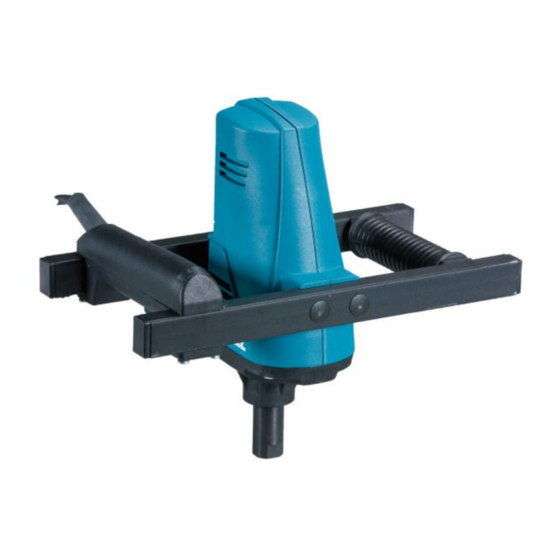
ECHNICAL INFORMATION
Model No.
Description
C
ONCEPT AND MAIN APPLICATIONS
This powerful 960W, 1-speed mixing tool is absolutely suitable as
step-in mixing machine for professional use.
Up to 30-40 kg / litres it is excellent suitable to cover the needs of
especially painters and tillers for mixing of paint, glue, tile cement etc.
S
pecification
Voltage (V)
110
120
220
230
240
Max blade diameter: mm (")
No load speed: min-
Rated speed: min-
Shank size of tool holder portion
Capacity (L)
Protection against electric shock
Power supply cord: m (ft)
Weight according to
EPTA-Procedure 01/2003: kg
S
tandard equipment
N/A
Note: The standard equipment may vary by country or model variation.
O
ptional accessories
N/A
UT1200
Hand-held Mixer
Current (A)
Cycle (Hz)
8.2
50/60
7.5
50/60
4.7
50/60
4.4
50/60
4.3
50/60
=rpm
1
=rpm
1
H07RN-F, 2x1,0mm², 3,15m, EU-plug = 230V-EU-model
H07RN-F, 2x1,0mm², 3,15m, GB-plug = 230V-GB-model
H07RN-F, 2x1,0mm², 3,15m, 4-h-plug = 110V-GB-model
Continuous Rating (W)
Input
Output
850
485
850
463
960
589
960
575
960
594
120
0-590 for 230V
0-550 for 110V
0-360 for 230V
0-400 for 110V
M14
40
Double insulation
3.2
OFFICIAL USE
for ASC & Sales Shop
PRODUCT
P 1/ 9
September 2015
H
W
L
Dimensions: mm
Length (L)
345
Width (W)
180
Height (H)
295
Torque (N·m)
11.6
9.6
16.2
14.6
14.0
Advertisement

Related Manuals for Makita UT1200


Summary of Contents for Makita UT1200
- Page 1 OFFICIAL USE for ASC & Sales Shop ECHNICAL INFORMATION PRODUCT P 1/ 9 Model No. UT1200 September 2015 Description Hand-held Mixer ONCEPT AND MAIN APPLICATIONS This powerful 960W, 1-speed mixing tool is absolutely suitable as step-in mixing machine for professional use.
- Page 2 Repair Manual UT1200 P 2/ 9...
- Page 3 I. General (a) The mixer should only be repaired by authorized service center. The following explanations are in accordance with the spare parts list UT1200. To avoid electric shock, unplug the mixer from the power supply before Attempting any service! II.
- Page 4 Now you are able to see switch (10), anti-parasite condenser (11), and line cord (12), two self-tapping screws (13) and wire locking flange (14). 2. Disassembly of Gearing Section To disassemble gear, prepare Round bar and one set of V-Block (1R258). Press down work spindle (20) with round bar in drilling direction.
- Page 5 Remove 4 cover caps from end of the upper metal bar and four plugs (36). Attention: Pressing a red circle as shown below with flat headed screw driver makes more efficient to remove 4 plugs(36). Remove four Screws (33) (TORX Type). Therefore you are able to separate bow handle (16) from motor housing...
- Page 6 While Pressing fit a bearing, do not press outer race. It may cause extraordinary noise and rotational motion fault. The correct way is to press inner race at equal power. UT1200 III. Assembly of Mixer At first Connect the intermediate wire of pair of brushes...
- Page 7 Set the grooved ball bearing (28), work spindle (20) and ball bearing (28) into the hole of gearbox housing (18). And then press the work spindle (20) with arbor press. And then insert grooved ball bearings (28) with repair tool 1R030 (Bearing setting pipe 25-17.2) and arbor...
- Page 8 Assembly of Switch Connect 2 lines (Blue and white lead wire) into terminals of switch (10) by turning slotted screw driver clockwise. (Please see the wiring diagram for further information). And then replace wiring locking flange (14) and screw 2 tapping screws (13) on wiring locking flange (14).
- Page 9 3. Wiring Diagram UT1200 IV. Checklist for testing the machine ➢ Check for correct assembly! ➢ Check the functionality of the machine! ➢ Test speed-adjustment in different switch positions! Check isolation of machine with high voltage (1500V)! ➢ V. Grease and Glue...