Makita LS1221 Instruction Manual
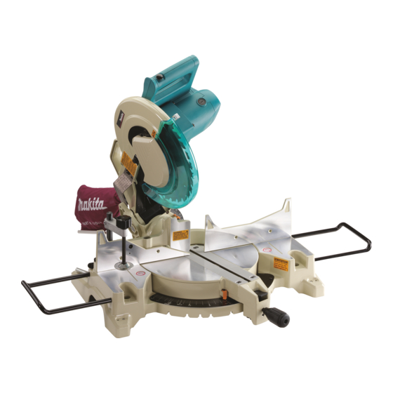
Compound miter saw
Hide thumbs
Also See for LS1221:
- Instruction manual (65 pages) ,
- Parts breakdown (5 pages) ,
- Instruction manual (8 pages)
Table of Contents
Advertisement
Quick Links
Advertisement
Table of Contents

Related Manuals for Makita LS1221


Summary of Contents for Makita LS1221
- Page 1 INSTRUCTION MANUAL Compound Miter Saw LS1221 DOUBLE INSULATION Read before use.
-
Page 2: Specifications
SPECIFICATIONS Model LS1221 Blade diameter 305 mm Hole diameter 25.4 mm or 30 mm (Country specific) Max. kerf thickness of the saw blade 3.2 mm Max. Miter angle Left 48°, Right 48° Max. Bevel angle Left 45° No load speed... -
Page 3: General Power Tool Safety Warnings
Do not operate power tools in explosive atmo- WARNING: Wear ear protection. spheres, such as in the presence of flammable liquids, gases or dust. Power tools create sparks WARNING: The noise emission during actual which may ignite the dust or fumes. use of the power tool can differ from the declared Keep children and bystanders away while value(s) depending on the ways in which the... -
Page 4: Safety Instructions For Mitre Saws
Remove any adjusting key or wrench before Maintain power tools and accessories. Check turning the power tool on. A wrench or a key left for misalignment or binding of moving parts, attached to a rotating part of the power tool may breakage of parts and any other condition that result in personal injury. - Page 5 13. The cut-off piece must not be jammed or pressed by any means against the spinning saw blade. If confined, i.e. using length stops, the cut-off piece could get wedged against the blade and thrown violently. 14. Always use a clamp or a fixture designed to properly support round material such as rods or tubing.
-
Page 6: Installation
Stopper pin which locks the cutter head down INSTALLATION is for carrying and storage purposes only and not for any cutting operations. Check the blade carefully for cracks or dam- Bench mounting age before operation. Replace cracked or dam- aged blade immediately. Gum and wood pitch When the tool is shipped, the handle is locked in the hardened on blades slows saw and increases lowered position by the stopper pin. -
Page 7: Functional Description
UV light exposure, First, unplug the tool. Loosen all the screws (2 each on left contact a Makita service center for a new guard. DO and right) securing the kerf boards. Re-tighten them only NOT DEFEAT OR REMOVE GUARD. -
Page 8: Adjusting The Miter Angle
Adjusting the miter angle CAUTION: • Before and after changing the bevel angle, always adjust the kerf boards as described above. Maintaining maximum cutting capacity This tool is factory adjusted to provide the maximum cutting capacity for a 305 mm saw blade. When installing a new blade, always check the lower limit position of the blade and if necessary, adjust it as follows:... -
Page 9: Switch Action
A switch in need of repair may result in unintentional operation and serious personal injury. Return tool to a Makita service center for proper repairs BEFORE further usage. ► 1. Wrench holder 2. Hex wrench The hex wrench is stored as shown in the figure. -
Page 10: Installing The Blade
• Use only the Makita hex wrench provided to install or remove the blade. Failure to do so may result in overtightening or insufficient tightening of the hex socket bolt. This could cause an injury. -
Page 11: Securing Workpiece
Connecting a vacuum cleaner When you wish to perform clean cutting operation, connect a Makita vacuum cleaner. ► 1. Support 2. Turn base Sub-fence Dust bag ► 1. Sub-fence This tool is equipped with the sub-fence which should ordinarily be positioned as shown in the figure. - Page 12 Vertical vise CAUTION: • Always rotate the vise nut to the right fully when securing the workpiece. Failure to do so may result in insufficient securing of the workpiece. This could cause the workpiece to be thrown, cause damage to the blade or cause the loss of control, which can result in PERSONAL INJURY.
-
Page 13: Operation
Bevel cut OPERATION CAUTION: • Before use, be sure to release the handle from the lowered position by pulling the stopper pin. • Make sure the blade is not contacting the work- piece, etc. before the switch is turned on. •... -
Page 14: Carrying Tool
Cutting aluminum extrusion Cutting repetitive lengths ► 1. Vise 2. Spacer block 3. Guide fence 4. Aluminum ► 1. Set plate 2. Holder 3. Screw extrusion 5. Spacer block When cutting several pieces of stock to the same When securing aluminum extrusions, use spacer length, ranging from 295 mm to 440 mm, use of blocks or pieces of scrap as shown in the figure to the set plate (optional accessory) will facilitate... -
Page 15: Maintenance
Loosen the grip which secures the turn base. Turn the turn base so that the pointer points to 0° on the miter scale. Then turn the turn base slightly clock- wise and counterclockwise to seat the turn base in the 0° miter notch. (Leave as it is if the pointer does not point to 0°.) Loosen the hex socket bolts securing the guide fence using the hex wrench. -
Page 16: Replacing Carbon Brushes
Bevel angle 45° bevel angle 0° bevel angle ► 1. Bevel scale 2. Pointer 3. Lever 4. 45° bevel angle adjusting bolt ► 1. Lever 2. Turn base 3. 0° bevel angle adjusting bolt Adjust the 45° bevel angle only after per- Lower the handle fully and lock it in the low- forming 0°... -
Page 17: After Use
OPTIONAL ACCESSORIES WARNING: These Makita accessories or attachments are recommended for use with your Makita tool specified in this manual. The use of any other accessories or attachments may result in serious personal injury. WARNING: Only use the Makita accessory or attachment for its stated purpose. - Page 20 Makita Corporation 3-11-8, Sumiyoshi-cho, Anjo, Aichi 446-8502 Japan 884409-913 www.makita.com 20180823...