
Related Manuals for GE LOGIQ e


Summary of Contents for GE LOGIQ e
- Page 1 Technical Publication LOGIQ e Basic Service Manual Direction Number: 5461614-100 English Rev. 6 All Material Copyright © 2014-2015 by General Electric Company Inc. All Rights Reserved.
- Page 2 Product Information This Manual covers the software version of R8.x.x for LOGIQ e ultrasound system. Copyright © 2014-2015, General Electric Company. GE Medical Systems, a General Electric Company, going to market as GE Manufacturer: GE Medical Systems (China) Co., Ltd.
- Page 3 MyWorkshop/ePDM (GE electronic Product Data Management). If you need to know the latest revision, contact your distributor, local GE Sales Representative or in the USA call the GE Ultrasound Clinical Answer Center at 1 800 682 5327 or 1 262 524 5698.
- Page 4 Important precautions Translation policy LOGIQ e – Basic Service Manual 5461614-100 English Rev. 6...
- Page 5 LOGIQ e – Basic Service Manual 5461614-100 English Rev. 6...
- Page 6 LOGIQ e – Basic Service Manual 5461614-100 English Rev. 6...
- Page 7 LOGIQ e – Basic Service Manual 5461614-100 English Rev. 6...
- Page 8 LOGIQ e – Basic Service Manual 5461614-100 English Rev. 6...
- Page 9 LOGIQ e – Basic Service Manual 5461614-100 English Rev. 6...
- Page 10 LOGIQ e – Basic Service Manual 5461614-100 English Rev. 6...
- Page 11 LOGIQ e – Basic Service Manual 5461614-100 English Rev. 6...
- Page 12 LOGIQ e – Basic Service Manual 5461614-100 English Rev. 6...
-
Page 13: Damage In Transportation
GE personnel. In performing all electrical work on these products, GE will use its own specially trained field engineers. All of GE’s electrical work on these products will comply with the requirements of the applicable electrical codes. -
Page 14: Omission And Errors
No. 19 Changjiang Road Wuxi National Hi-Tech Dev. Zone Jiangsu P.R.China 214028 GE employees should use TrackWise to report service documentation issues. These issues will then be in the internal problem reporting tool and communicated to the writer. i-12 LOGIQ e –... -
Page 15: Service Safety Considerations
For a complete review of all safety requirements, refer to Chapter 1 in the Service Manual. LOGIQ e – Basic Service Manual i-13 5461614-100 English Rev. 6... -
Page 16: Legal Notes
If you are a GE employee or a customer who has entered into such a license agreement with GE to use this proprietary software, you are authorized to use this Material according to the conditions stated in your license agreement. -
Page 17: Table Of Contents
Proprietary to GE - - - - - - - - - - - - - - - - - - - - - - - - - - - - - - - - - - - - -... - Page 18 Receiving the LOGIQ e - - - - - - - - - - - - - - - - - - - - - - - - - - - - - - - - - - - 3-6...
- Page 19 LOGIQ e configuration - - - - - - - - - - - - - - - - - - - - - - - - - - - - - - - - - - 3-20 Connecting Cables - - - - - - - - - - - - - - - - - - - - - - - - - - - - - - - - - - - - - 3-22...
- Page 20 Warnings - - - - - - - - - - - - - - - - - - - - - - - - - - - - - - - - - - - - - - - - - - - - - 8-3 Returning/shipping probes and repair parts - - - - - - - - - - - - - - - - - - - - - 8-4 i-18 LOGIQ e – Basic Service Manual 5461614-100 English Rev. 6...
- Page 21 Standard GE tool kit - - - - - - - - - - - - - - - - - - - - - - - - - - - - - - - - - - - 10-13...
- Page 22 Overview - - - - - - - - - - - - - - - - - - - - - - - - - - - - - - - - - - - - - - - - - - - 11-43 i-20 LOGIQ e – Basic Service Manual 5461614-100 English Rev. 6...
- Page 23 Inspection Paper Work - - - - - - - - - - - - - - - - - - - - - - - - - - - - - - - - - 12-35 Index LOGIQ e – Basic Service Manual i-21...
- Page 24 LOGIQ e – Basic Service Manual 5461614-100 English Rev. 6...
-
Page 25: Chapter 1 - Introduction
This chapter describes important issues related to safely servicing the Ultrasound system and Docking Cart. The service provider must read and understand all the information presented here before installing or servicing the units. LOGIQ e – Basic Service Manual 5461614-100 English Rev. 6... -
Page 26: Overview
• ‘Lockout/Tagout (LOTO) requirements’ on page 1-29 • ‘Returning probes and repair parts’ on page 1-30 • ‘EMC, EMI and ESD’ on page 1-31 • ‘Customer assistance’ on page 1-33 LOGIQ e – Basic Service Manual 5461614-100 English Rev. 6... -
Page 27: Manual Overview
Manual Overview Manual Overview This manual provides installation and service information for the LOGIQ e Ultrasound system and docking cart. It is divided in twelve chapters as shown below. Contents in This Section • ‘Contents in this service manual’ on page 1-3 •... -
Page 28: Typical Users Of The Basic Service Manual
Functions (Theory)’ explanations of the electronics for the system. ‘Service Contains instructions on how to make any Adjustments’ available adjustments to the LOGIQ e system. ‘Diagnostics/ Provides procedures for running diagnostic or Troubleshooting’ related routines for the LOGIQ e system. -
Page 29: Logiq E Models Covered By This Manual
LOGIQ e models. Purpose of the operator manual(s) The operator manuals should be fully read and understood before operating the LOGIQ e and also kept near the unit for quick reference. The online versions of the operator manuals are available via the Help function on LOGIQ e’s operator panel. -
Page 30: General Caution
Storage rack (1) is 2kg, DVD-RW Shelf (2) is 2kg, B/W Printer Shelf (3) is 4kg, Color Printer Shelf (4) is 7kg, refer to the following figure. Figure 1-1. Capacity load of the Docking Cart LOGIQ e – Basic Service Manual 5461614-100 English Rev. 6... -
Page 31: Important Conventions
Conventions used in book Important conventions, used in this document, are described next. Model designations This manual covers the LOGIQ e Ultrasound systems listed in: ‘LOGIQ e models covered by this manual’ on page 1-5. Icons Pictures, or icons, are used wherever they will reinforce the printed message. - Page 32 Notes are used to provide important information about an item or a procedure. NOTE: Be sure to read the notes; the information contained in a note can often save you time or effort. LOGIQ e – Basic Service Manual 5461614-100 English Rev. 6...
-
Page 33: Standard Hazard Icons
Standard hazard icons ELECTRICAL MECHANICAL RADIATION LASER HEAT PINCH NOTE: Even if a symbol isn’t used on the product or in this manual, it may be included for your reference. LOGIQ e – Basic Service Manual 5461614-100 English Rev. 6... - Page 34 Wear Eye Protection Hand Protection Foot Protection Wear Eye Protection Be sure to read the notes; the information contained in a note can often save you time or effort. 1-10 LOGIQ e – Basic Service Manual 5461614-100 English Rev. 6...
-
Page 35: Product Icons
See ISO 8601 for date formats. Catalog or model number Bottom REF REF Serial number Bottom SN SN Direct Current: For products to Bottom be powered from a DC supply LOGIQ e – Basic Service Manual 1-11 5461614-100 English Rev. 6... -
Page 36: Introduction
For use with adapter GE part Bottom number 5460229-x Description Bottom Model Rear of Docking Cart Only for use with LOGIQ e Rear of Docking Cart series (Software version R8.x.x) Made in China Rear of Docking Cart Type/Class Label Used to indicate the degree of safety or protection. - Page 37 Do not push the system. Rear of Docking Cart/ Isolation Cart LOGIQ e – Basic Service Manual 1-13 5461614-100 English Rev. 6...
- Page 38 Information on the potential effects on the environment and human health of the substances used in batteries is available at this url: http://www.gehealthcare.com/ euen/weee-recycling/index.html 1-14 LOGIQ e – Basic Service Manual 5461614-100 English Rev. 6...
- Page 39 LOGIQ e – Basic Service Manual 1-15 5461614-100 English Rev. 6...
- Page 40 (Within this system, the backlight lamps in the monitor display, contain mercury.) 1-16 LOGIQ e – Basic Service Manual 5461614-100 English Rev. 6...
- Page 41 Port from the system before lifting up the system. Do not disconnect the probe Probe Connector of connector of Three-probe Port Three-Probe Port from the system when the system is in use. LOGIQ e – Basic Service Manual 1-17 5461614-100 English Rev. 6...
- Page 42 When pushing the Extended Power Box Life Battery in to the power box, use caution to avoid injuring fingers and hands. 1-18 LOGIQ e – Basic Service Manual 5461614-100 English Rev. 6...
-
Page 43: Contents In This Section
DEATH, ARE PRESENT IN THIS EQUIPMENT. USE EXTREME CAUTION WHEN HANDLING, TESTING AND ADJUSTING. If the covers are removed from an operating LOGIQ e, some WARNING metal surfaces may be warm enough to pose a potential heat hazard if touched, even while in shutdown mode. - Page 44 DO NOT substitute parts or modify equipment WARNING Because of the danger of introducing additional hazards, ONLY install GE approved parts. DO NOT perform any unauthorized modification of the equipment. Ensure that the Ultrasound system is turned off and unplugged...
- Page 45 WARNING sharp edges are encountered, the appropriate PPE should be used to reduce the risk of injury. Wear all PPE including gloves as indicated in the chemical WARNING MSDS. LOGIQ e – Basic Service Manual 1-21 5461614-100 English Rev. 6...
-
Page 46: Mechanical Safety
Never use a probe that has fallen to the floor. Even if it looks WARNING OK, it may be damaged. LOGIQ e system weighs 5.2 kg or more, depending on CAUTION installed peripherals, when ready for use. Care must be used when moving it or replacing its parts. - Page 47 Docking Cart to water or any kind of liquid. Never set liquids on the Docking Cart to ensure that liquid does not drip into the unit Put peripherals in correct position to avoid Docking Cart CAUTION overload. LOGIQ e – Basic Service Manual 1-23 5461614-100 English Rev. 6...
-
Page 48: Electrical Safety
• Both the system power cable and the power connector must meet international electrical standards Connecting a LOGIQ e to the wrong voltage level will most WARNING likely destroy it. 1-24 LOGIQ e – Basic Service Manual... - Page 49 Do not use a damaged or defective probe. • Never immerse the probe connector or adapter into any liquid. Peripherals Refer to the Patient Safety Environment section of the User’s Manual for peripheral isolation information. LOGIQ e – Basic Service Manual 1-25 5461614-100 English Rev. 6...
-
Page 50: Battery Safety
Do not contact PCM (Power Control and Monitor, it’s a small board in the battery) directly to prevent packs from ESD damage. • In case of longer non-use of the LOGIQ e, please make sure the battery is removed. 1-26 LOGIQ e – Basic Service Manual... - Page 51 The battery shall be shipped in about 30% charged state. Those packs have to be fully charged and discharged up to 3 times to utilize Li-lon smart packs before use. LOGIQ e – Basic Service Manual 1-27 5461614-100 English Rev. 6...
-
Page 52: Dangerous Procedure Warnings
DEATH, ARE PRESENT IN THIS EQUIPMENT. USE EXTREME CAUTION WHEN HANDLING, TESTING AND ADJUSTING. If the covers are removed from an operating LOGIQ e, some WARNING metal surfaces may be warm enough to pose a potential heat hazard if touched, even while in shutdown mode. -
Page 53: Lockout/Tagout (Loto) Requirements
6. Control all stored and residual energy. 7. Verify isolation. All potentially hazardous stored or residual energy is relieved. Energy Control and Power Lockout for LOGIQ e. WARNING When servicing parts of the Ultrasound system where there is exposure to voltage greater than 30 volts: 1. -
Page 54: Returning Probes And Repair Parts
It is always possible during system failure and repair to lose patient data. GE is not responsible for the loss of this data. If PHI (Patient Healthcare Information) data needs to be sent to GE employees for service purposes, GE will ascertain agreement from the customer. -
Page 55: Emc, Emi And Esd
CE Compliance LOGIQ e conforms to all applicable conducted and radiated emission limits and to immunity from electrostatic discharge, radiated and conducted RF fields, magnetic fields and power line transient requirements. -
Page 56: Electrostatic Discharge (Esd) Prevention
Always use non-conductive handles designed for the removal and replacement of ESD sensitive parts. All parts that have the potential for storing energy must be discharged or isolated before making contact. 1-32 LOGIQ e – Basic Service Manual 5461614-100 English Rev. 6... -
Page 57: Customer Assistance
6. Imaging mode, probe, preset/application. 7. Media brand, speed, capacity, type. 8. Save secondary image capture, cine loop, 4D multi-volume loop. NOTE: Restart the application before resuming clinical scanning. LOGIQ e – Basic Service Manual 1-33 5461614-100 English Rev. 6... -
Page 58: Phone Numbers For Customer Assistance
Latin America Service 1-262-524-5300 Application Support 1-262-524-5698 Europe Phone: +33 (0) 130-831-300 GE Ultraschall Deutschland Gmbh & Co. KG (General Imaging and Cardiac) Beethovenstrasse 239 +49 (0) 212-2802-652 Postfach 11 05 60, D-42655 Solingen Fax: +49 (0) 2122-8024-31 Germany Asia (Singapore) -
Page 59: Factory Site
System manufacturer MANUFACTURER PHONE NUMBER FAX NUMBER GE Medical Systems (China) Co., Ltd. +86 510 85225888 +86 510 85226688 No.19 Changjiang Road WuXi National Hi-Tech Development Zone Jiangsu P.R.China 214028 LOGIQ e – Basic Service Manual 1-35 5461614-100 English Rev. 6... - Page 60 Introduction 1-36 LOGIQ e – Basic Service Manual 5461614-100 English Rev. 6...
-
Page 61: Chapter 2 - Site Preparations
Ultrasound system and Docking Cart. Included are descriptions of the facility and electrical needs to be met by the purchaser of the units. LOGIQ e – Basic Service Manual 5461614-100 English Rev. 6... -
Page 62: Overview
Site Preparations Overview Contents in this chapter • ‘Overview’ on page 2-2 • ‘General requirements’ on page 2-3 • ‘Facility needs’ on page 2-12 • ‘Environmental Dangers’ on page 2-19 LOGIQ e – Basic Service Manual 5461614-100 English Rev. 6... -
Page 63: General Requirements
If the Ultrasound system is very cold or hot, do not turn on its CAUTION power until it has had a chance to acclimate to its operating environment. Table 2-1: System Acclimation Time Chart Degree C Degree F hours LOGIQ e – Basic Service Manual 5461614-100 English Rev. 6... - Page 64 50 - 104°F 23 - 122°F 23 - 122°F Humidity 30 - 75% 10 - 90% 10 - 90% non-condensing non-condensing non-condensing Pressure 700 - 1060hPa 700 - 1060hPa 700 - 1060hPa LOGIQ e – Basic Service Manual 5461614-100 English Rev. 6...
- Page 65 F (ºF): (ºF) = (ºC * 9/5) + 32 Ensure that the probe face temperature does not exceed the CAUTION normal operation temperature range. The LOGIQ e system and probe connector is not waterproof. CAUTION Do not expose the device to water or any kind of liquid. Lighting Bright light is needed for Ultrasound system installation, updates and repairs.
-
Page 66: Electrical Requirements
Site Preparations Electrical requirements General requirements NOTE: GE requires a dedicated power and ground for the proper operation of its Ultrasound equipment. This dedicated power shall originate at the last distribution panel before the Ultrasound system. Sites with a mains power system with defined Neutral and Live:... - Page 67 General requirements Site circuit breaker Power outage may occur. The LOGIQ e requires a dedicated CAUTION single branch circuit. To avoid circuit overload and possible loss of critical care equipment, make sure you do not have any other equipment operating on the same circuit.
- Page 68 1 millisecond for any type of transient, including line frequency, synchronous, asynchronous, or aperiodic transients. Decaying Oscillation All applications Less than 15% of peak voltage for less than 1 millisecond. LOGIQ e – Basic Service Manual 5461614-100 English Rev. 6...
-
Page 69: Emi Limitations
High Frequency (HF) surgery equipment • general AC/DC adapters The presence of a broadcast station or broadcast van may also cause interference. See: ‘EMI prevention/abatement’ on page 2-10 for EMI prevention tips. LOGIQ e – Basic Service Manual 5461614-100 English Rev. 6... - Page 70 Where applicable, do not allow cables to lie across the top of the Card Rack or peripheral cables hang out of the peripheral bays. Loop the excess length for peripheral cables inside the peripheral bays. Attach the monitor cables to the frame. 2-10 LOGIQ e – Basic Service Manual 5461614-100 English Rev. 6...
-
Page 71: Probes Environmental Requirements
FOR STORAGE TEMPERATURES OF -5 TO + 50 degrees C. WHEN EXPOSED TO LARGE TEMPERATURE VARIATIONS, THE PRODUCT SHOULD BE KEPT IN ROOM TEMPERATURE FOR 10 HOURS BEFORE USE. LOGIQ e – Basic Service Manual 2-11 5461614-100 English Rev. 6... -
Page 72: Facility Needs
All electrical work on these products must comply with the requirements of applicable electrical codes. The purchaser of GE equipment must only utilize qualified personnel to perform electrical servicing on the equipment. The desire to use a non–listed or customer provided product or... -
Page 73: Required Facility Needs
Facility needs Required facility needs NOTE: GE requires a dedicated power and ground for the proper operation of its Ultrasound equipment. This dedicated power shall originate at the last distribution panel before the Ultrasound system. Sites with a mains power system with defined Neutral and Live:... -
Page 74: Desirable Features
Storage for linens and equipment • Nearby waiting room, lavatory, and dressing room • Dual level lighting (bright and dim) • Lockable cabinet ordered by GE for its software and proprietary manuals 2-14 LOGIQ e – Basic Service Manual 5461614-100 English Rev. 6... -
Page 75: Suggested And Alternate Ultrasound Room Layout
A ND MA NU A LS (193 C M) DOO R 30 IN . (76 C M) A n 8 by 10 foot Minimal F loor P lan Figure 2-1. Suggested Ultrasound Room Layout LOGIQ e – Basic Service Manual 2-15 5461614-100 English Rev. 6... -
Page 76: Networking Setup Requirements
With DICOM, images can be archived, stored, and retrieved faster, easier, and at a lower cost. 2-16 LOGIQ e – Basic Service Manual 5461614-100 English Rev. 6... - Page 77 Ultrasound system for DICOM APPLICATION INFORMATION. A field for the make (manufacturer) and the revision of the device, is also included. This information may be useful for error solving. LOGIQ e – Basic Service Manual 2-17 5461614-100 English Rev. 6...
- Page 78 Site Preparations DICOM option setup requirements (continued) Figure 2-2. Worksheet for DICOM Network Information 2-18 LOGIQ e – Basic Service Manual 5461614-100 English Rev. 6...
-
Page 79: Environmental Dangers
Patient Environment. The patient environment/vicinity will be depicted as a dashed line in this procedure. See example below. 1. Patient environment Figure 2-3. Patient environment LOGIQ e – Basic Service Manual 2-19 5461614-100 English Rev. 6... - Page 80 Site Preparations 2-20 LOGIQ e – Basic Service Manual 5461614-100 English Rev. 6...
-
Page 81: Chapter 3 - System Setup
How to prepare the facility and unit of the actual installation, and how to check and test the unit, probes, and external peripherals for electrical safety are also included in this procedure. LOGIQ e – Basic Service Manual 5461614-100 English Rev. 6... -
Page 82: Overview
‘Completing the setup’ on page 3-12 • ‘System Configuration’ on page 3-19 • ‘Connectivity setup’ on page 3-31 • ‘Paperwork after setup’ on page 3-33 • ‘Peripherals Installation Instructions’ on page 3-38 LOGIQ e – Basic Service Manual 5461614-100 English Rev. 6... -
Page 83: Setup Reminders
• Set up LOGIQ e wo/options: 30 minutes • DICOM Network Configuration: 30 minutes The LOGIQ e installation and functional checkout will take approximately one hour. LOGIQ e consoles with optional equipment may take slightly longer. Setup warnings WHEN USING ANY TEST INSTRUMENT THAT IS CAPABLE DANGER OF OPENING THE AC GROUND LINE (I.E., METER’S... - Page 84 If the Ultrasound system is very cold or hot, do not turn on its CAUTION power until it has had a chance to acclimate to its operating environment. The following table describes guidelines for reaching operational temperatures from storage or transport temperatures. LOGIQ e – Basic Service Manual 5461614-100 English Rev. 6...
- Page 85 Operator Manual(s) CAUTION The User Manual(s) should be fully read and understood before operating the LOGIQ e and kept near the Ultrasound system for quick reference. Acoustic Output Hazard CAUTION Although the ultrasound energy transmitted from the LOGIQ e probe is within AIUM/NEMA standards, avoid unnecessary exposure.
-
Page 86: Receiving And Unpacking The Equipment
System Setup Receiving and unpacking the equipment Contents in this Section • ‘Receiving the LOGIQ e’ on page 3-6 • ‘Unpacking the LOGIQ e’ on page 3-7 • ‘Moving into Position’ on page 3-10 Receiving the LOGIQ e Overview Improper handling during transportation may harm the equipment inside the package even if the package itself is undamaged. -
Page 87: Unpacking The Logiq E
1. Cut the four PLASTIC BANDs 2. Cut the adhesive tape and open top covers of paper carton. Adhesive tape Plastic Bands Figure 3-1. Open Top Covers of Paper Carton LOGIQ e – Basic Service Manual 5461614-100 English Rev. 6... - Page 88 6. Take out Accessories Package. Paper Pad Console and interleavers Console Package Accessories Package Figure 3-2. Unpacking the equipment Do not lift the unit by the rubber band. Equipment damage CAUTION may result. LOGIQ e – Basic Service Manual 5461614-100 English Rev. 6...
- Page 89 Receiving and unpacking the equipment Unpacking the LOGIQ e (continued) 7. Remove 2 interleavers. 8. Remove plastic bag. Interleaver Console Interleaver Figure 3-3. Removing interleavers and plastic bag LOGIQ e – Basic Service Manual 5461614-100 English Rev. 6...
-
Page 90: Packing The Equipment
Figure 3-4. Labels on Package Please carefully unpack the system, and do not dispose the CAUTION package of LOGIQ e, so that it can be reused for service. Moving into Position Do not lift the unit by the rubber band. Use handle to move CAUTION system. -
Page 91: Preparing For Setup
• Verify that the scanner is set to the correct voltage. The Voltage settings for the LOGIQ e Scanner is found on a label located on the AC adapter. • 220-240VAC(China); 100-120VAC(USA/Japan);... -
Page 92: Completing The Setup
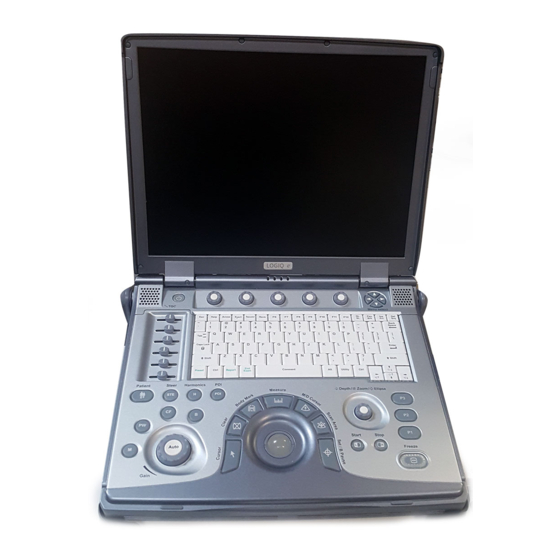
Length: 346 mm (13.62 in) console only; 375 mm (14.76 in) with handle • Width: 295 mm (11.61 in) console only; 343 mm (13.50 in) with handle Console Weight • Weight (with battery): approx. 5.2 kg (11.5 lbs) 3-12 LOGIQ e – Basic Service Manual 5461614-100 English Rev. 6... -
Page 93: Electrical Specifications
Completing the setup Electrical specifications Connecting a LOGIQ e to the wrong voltage level will most WARNING likely destroy it. Verification of the system’s voltage setting Verify that the mains voltage specified for the LOGIQ e is available on-site. Electrical specifications for LOGIQ e Figure 3-5. -
Page 94: Power On / Boot Up
When power is applied to the system, power is distributed to the Cooling Unit, Control Panel, LCD, Peripherals and the Back-end Processor. The system should rest on the handle to allow an air gap to CAUTION prevent overheating. 3-14 LOGIQ e – Basic Service Manual 5461614-100 English Rev. 6... - Page 95 When the Power On/Off switch on the Control Panel is pressed once, the Back-end Processor starts and the software code is distributed to initiate the scanner. No status messages are displayed during this process. LOGIQ e – Basic Service Manual 3-15 5461614-100 English Rev. 6...
-
Page 96: Power Off/Shutdown
5. Disconnect the probes.Clean or disinfect all probes as necessary. Store them in their shipping cases to avoid damage. 6. Close LCD cover. System Shutdown Disconnect the Mains Power Cable if necessary. For example: Relocating the system. 3-16 LOGIQ e – Basic Service Manual 5461614-100 English Rev. 6... -
Page 97: Connecting Probes
Do a visual check of the probe pins and system sockets. b. Remove any dust or foam rests from the probe pins. c. Verify the probe and the probe cable for any visual damage. LOGIQ e – Basic Service Manual 3-17 5461614-100 English Rev. 6... - Page 98 Follow these steps to disconnect a probe: 1. Remove the connector from the port. 2. Ensure that the probe head is clean before placing the probe in its storage case. 3-18 LOGIQ e – Basic Service Manual 5461614-100 English Rev. 6...
-
Page 99: System Configuration
System Configuration System Configuration Contents in this Section • ‘LOGIQ e configuration’ on page 3-20 • ‘Electrical requirements for Adapter’ on page 3-21 • ‘Approved peripherals’ on page 3-21 • ‘Connecting Cables’ on page 3-22 • ‘Peripheral/Accessories Connector Panel’ on page 3-23 •... -
Page 100: Logiq E Configuration
System Setup LOGIQ e configuration System Specification The physical dimensions of the LOGIQ e console with old LCD are summarized as below: Table 3-1: Physical Dimensions of LOGIQ e Height Width Depth Unit Console Console Console Console with Console with... - Page 101 Wireless USB Micro Adapter ECG-USB NORAV ECGUSB1D-EX USB Port Barcode Scanner Honeywell XENON 1900 USB Port NOTE: For detailed installation information and connection procedures, please refer to Peripheral Installation manual. LOGIQ e – Basic Service Manual 3-21 5461614-100 English Rev. 6...
-
Page 102: Connecting Cables
System Setup Connecting Cables Equipment damage possibility. Be sure to use the following WARNING recommended connecting cables to connect recording devices and a network with LOGIQ e console. Table 3-4: List of Connecting Cables Name Part No. Figure NOTE USB Cable For USB Printer &... -
Page 103: Peripheral/Accessories Connector Panel
System Configuration Peripheral/Accessories Connector Panel LOGIQ e peripherals and accessories can be properly connected using the side connector panel. Figure 3-11. Left Side and Rear Connector Panel 1. 3 USB Ports for Printers (B/W, Color and USB), Memory Stick, Footswitch, DVD-RW, Wireless LAN Adapter, USB Hub, USB HDD, ECG 2. - Page 104 Pin Assignment of USB2 Pin No. Signal Pin No. Signal +5VDC DATA+ DATA- Pin Assignment of USB3 Table 3-8: Pin Assignment of USB3 Pin No. Signal Pin No. Signal +5VDC DATA+ DATA- 3-24 LOGIQ e – Basic Service Manual 5461614-100 English Rev. 6...
- Page 105 TMDS Data2- TMDS Data1+ Reserved (N.C. on device) TMDS Data1 Shield TMDS Data1- TMDS Data0+ DDC/CEC Ground TMDS Data0 Shield +5V Power TMDS Data0- Hot Plug Detect TMDS Clock+ LOGIQ e – Basic Service Manual 3-25 5461614-100 English Rev. 6...
- Page 106 SD Card into the SD Card port. Connect Wireless LAN Adapter. Connect the Wireless LAN Adapter to the system. The wireless LAN adapter can be properly connected using either of the 3 USB ports. 3-26 LOGIQ e – Basic Service Manual 5461614-100 English Rev. 6...
- Page 107 The Barcode Reader can be properly connected using either of the 3 USB ports. Connect HDMI. Connect the external monitor to the system. The monitor can be properly connected using the HDMI port. LOGIQ e – Basic Service Manual 3-27 5461614-100 English Rev. 6...
- Page 108 1. Connect HDMI cable to the system and the external monitor. 2. Press Ctrl+Alt+V on the keyboard of the system, a dialog box appears on the screen. 3. Select Clone Displays in the menu list of Operating Mode. 3-28 LOGIQ e – Basic Service Manual 5461614-100 English Rev. 6...
- Page 109 Then select Close to close the dialog box. 5. To exit external monitor, Press Ctrl+Alt+V. Select Single Display in the menu list of Operating Mode, then select Next and Close. LOGIQ e – Basic Service Manual 3-29 5461614-100 English Rev. 6...
-
Page 110: Available Probes
System Setup Available probes See in specification in the LOGIQ e User Reference Manual for Probes and intended use. The LOGIQ e system supports C1-5-RS, 8C-RS, 9L-RS, 12L-RS, L4-12t-RS, L8-18i-RS, L10-22-RS, E8C-RS, 3Sc-RS and 6S-RS probes. Table 3-11: List of Probes for LOGIQ e... -
Page 111: Software Options Configuration
System Configuration Software Options configuration Software Option installation introduction Refer to the LOGIQ e Basic User Manual, Chapter 16, Customizing Your System for information on configuring items like Hospital, Department, Language, Units (of measure), Date, Time and Date Format. For information on configuring Software Options, Refer to the LOGIQ e Basic User Manual, Chapter 16, Customizing Your System. - Page 112 IP Address: Remote Archive IP: Subnet Mask: Remote Archive Name: Default Gateway: Services (Destination Devices) Device Type Manufacturer Name IP Address Port AE Title Figure 3-12. Connectivity Installation Worksheet 3-32 LOGIQ e – Basic Service Manual 5461614-100 English Rev. 6...
-
Page 113: Paperwork After Setup
During and after setup, the documentation (i.e. CDs with documentation, User Manuals, Installation Manuals, etc.) for the LOGIQ e and the peripherals must be kept as part of the original Ultrasound system documentation. This ensures that all relevant safety and user information is available during the operation and service of the complete Ultrasound system. -
Page 114: Peripherals Installation
‘Footswitch Installation’ on page 3-45 • ‘Barcode Scanner Installation’ on page 3-47 • ‘ECG Installation’ on page 3-50 • ‘ECG Intended Use’ on page 3-51 • ‘Technical Specification of ECG’ on page 3-52 3-34 LOGIQ e – Basic Service Manual 5461614-100 English Rev. 6... -
Page 115: Overview
Peripherals Installation Overview This section describes how to install and configure the peripherals validated for the LOGIQ e. About the operation check-out of peripherals, See ‘Peripheral Checks’ on page 4-52 for more information. Table 3-12: LOGIQ e Peripherals Description Power... -
Page 116: Furnished Materials
Note UP-D25MD Color USB Printer Paper Roll AC Power Cord USB cable • DVD-RW (LITEON DVD-RW) Table 3-15: Materials furnished with DVD-RW Item Description Quantity Note DVD-RW USB cable 3-36 LOGIQ e – Basic Service Manual 5461614-100 English Rev. 6... - Page 117 Materials furnished with the Wireless LAN Item Description Quantity Note Wireless Adapter • 3 Pedal Footswitch Table 3-17: Materials furnished with the Footswitch Item Description Quantity Note Footswitch • Barcode Scanner LOGIQ e – Basic Service Manual 3-37 5461614-100 English Rev. 6...
-
Page 118: Peripherals Installation Instructions
2. Connect power cord and USB Cable on the Printer. Figure 3-14. Color Printer USB cable and Power Cord connect 3. Connect the power cord to the outlet on the wall, then turn on the printer. 3-38 LOGIQ e – Basic Service Manual 5461614-100 English Rev. 6... - Page 119 Peripherals Installation Color USB Printer Installation (continued) 4. Connect USB cable to LOGIQ e USB port. Figure 3-15. Color Printer connection Setting up Color printer for Printing Report 1. Connect the color printer to the USB port of the system.
- Page 120 Printflow View field and select “<<“. Figure 3-18. Button Page 3. Select Standard Print, then press “>>“ to add the standard printer to the Printflow View. Figure 3-19. Standard Print setting 3-40 LOGIQ e – Basic Service Manual 5461614-100 English Rev. 6...
- Page 121 2. Ensure no physical damage. Installation Procedure 1. Place the device in a suitable place. 2. Connect the USB Cable on the DVD-RW. Figure 3-20. Connect USB cable on DVD-RW LOGIQ e – Basic Service Manual 3-41 5461614-100 English Rev. 6...
- Page 122 System Setup DVD-RW Installation (continued) 3. Connect USB cable to LOGIQ e USB port. Figure 3-21. DVD-RW connection Do Not connect DVD-RW with the system while scanning. WARNING 3-42 LOGIQ e – Basic Service Manual 5461614-100 English Rev. 6...
- Page 123 2. Ensure no physical damage. Installation Procedure 1. Connect the Wireless LAN Adapter to the USB port on the LOGIQ e system. Figure 3-22. Connect Wireless LAN Adapter to the system LOGIQ e – Basic Service Manual 3-43 5461614-100 English Rev. 6...
- Page 124 Wireless Lan Adapter Installation (continued) 2. Enter Utility -> Connectivity -> TCP/IP and select Configuration to configure wireless network. Figure 3-23. Wireless configuration 3. Config the wireless Lan setting with local IT person. 3-44 LOGIQ e – Basic Service Manual 5461614-100 English Rev. 6...
- Page 125 One person 5 min. Preparations 1. Unpack the Footswitch. 2. Ensure no physical damage. Installation Procedure 1. Connect the Footswitch to the USB port on the LOGIQ e system. Figure 3-24. Connect Footswitch to the system LOGIQ e – Basic Service Manual 3-45...
- Page 126 Step (Scan Assistant), Scan Assistant Pause/Resume or Mark Cine. The default setting is No Function. Enter Utility -> Application -> Settings to configure the Footswitch functions. Figure 3-25. Configuring Footswitch Functions 3-46 LOGIQ e – Basic Service Manual 5461614-100 English Rev. 6...
- Page 127 2. Ensure no physical damage. Installation Procedure 1. Connect the Barcode Scanner to the USB port on the LOGIQ e system. Figure 3-26. Connect Barcode Scanner to the system LOGIQ e – Basic Service Manual 3-47 5461614-100 English Rev. 6...
- Page 128 NOTE: After the Barcode Scanner is connected to the Docking Cart, the cable of the Barcode Scanner can be hung in the cable hook. Figure 3-27. Barcode Scanner cable 3-48 LOGIQ e – Basic Service Manual 5461614-100 English Rev. 6...
- Page 129 Only the printed barcodes on the paper can be scanned. If you do not have the printed version, be sure to print them to the paper first and scan them on the paper. LOGIQ e – Basic Service Manual 3-49 5461614-100 English Rev. 6...
- Page 130 1. Unpack the ECG. 2. Ensure no physical damage. Figure 3-29. ECG Installation Procedure 1. Connect the ECG to the USB port on the system. Figure 3-30. ECG Installation 3-50 LOGIQ e – Basic Service Manual 5461614-100 English Rev. 6...
- Page 131 • Patients with suspected cardiac abnormalities • Populations of patients at an age or period in which a routine baseline evaluation of ECG characteristics is desired. LOGIQ e – Basic Service Manual 3-51 5461614-100 English Rev. 6...
- Page 132 Patient leakage current < 10 uA Ground Isolation 4 kV rms Input Impedance >100 Mohm CMMR > 100 dB DC max.input +/- 300mv Frequency range (-3db) 0.05 - 150 Hz 3-52 LOGIQ e – Basic Service Manual 5461614-100 English Rev. 6...
- Page 133 USB 2.0 compliant, Full Speed Device Control, Isochronous Transfer Types Environmental Operating Temperature Range 0°C to 50°C Storage Temperature Range: -40°C to 70°C Relative Humidity 0-85% non-condensing Regulatory Safety Standards IEC601-1 , IEC601-1-25 LOGIQ e – Basic Service Manual 3-53 5461614-100 English Rev. 6...
- Page 134 System Setup 3-54 LOGIQ e – Basic Service Manual 5461614-100 English Rev. 6...
-
Page 135: Chapter 4 - General Procedures And Functional Checks
Chapter 4 General Procedures and Functional Checks This chapter provides procedures for quickly checking major functions of the LOGIQ e and diagnostics instructions using the built-in service software and power supply adjustments. LOGIQ e – Basic Service Manual 5461614-100 English Rev. 6... -
Page 136: Overview
‘Functional checks’ on page 4-17 Special Equipment required To perform these tests, you'll need any of the sector, linear, or convex transducers. (Normally you should check all the transducers used on the system). LOGIQ e – Basic Service Manual 5461614-100 English Rev. 6... -
Page 137: General Procedures
‘Power ON/Boot Up’ on page 4-5 • ‘Connect AC/DC to the LOGIQ e’ on page 4-6 • ‘Switch ON the AC Power to LOGIQ e’ on page 4-8 • ‘Power shut down’ on page 4-11 • ‘Removable media’ on page 4-13 •... -
Page 138: Caution And Warning
The covers are required for safe operation, good Ultrasound system performance and cooling purposes. Energy Control and Power Lockout for LOGIQ e. WARNING When servicing parts of the Ultrasound system where there is exposure to voltage greater than 30 volts: 1. -
Page 139: Power On/Boot Up
The covers are required for safe operation, good Ultrasound system performance and cooling purposes. Use only power supply cords, cables and plugs provided by or CAUTION designated by GE. LOGIQ e – Basic Service Manual 5461614-100 English Rev. 6... - Page 140 General Procedures and Functional Checks Connect AC/DC to the LOGIQ e Connecting AC/DC to the LOGIQ e ultrasound unit, involves preliminary checks of the power cord, voltage level and compliance with electrical safety requirements. 1. Ensure that the wall outlet is of appropriate type.
- Page 141 General procedures Connect AC/DC to the LOGIQ e (continued) Lower the handle. Plug the AC adapter output connector into the system DC input port (located on the system’s rear panel) with the arrow side upward. Plug the AC adapter power cord into a grounded, protective earth outlet.
- Page 142 General Procedures and Functional Checks Switch ON the AC Power to LOGIQ e When power is applied to the scanner, power is distributed to the Cooling Unit, Control Panel, LCD, Peripherals and the Back-end Processor. 1. Press the Power On/Off switch at the front of the system once.
- Page 143 This warning message is to remind the user to check the system date in case the system date and time is incorrect. Figure 4-3. Check system date and time message LOGIQ e – Basic Service Manual 5461614-100 English Rev. 6...
- Page 144 1. Enter Utility -> System -> General -> Date/Time. 2. Reset the system date and time. 3. Select Apply and select OK. 4. Select Save. 4-10 LOGIQ e – Basic Service Manual 5461614-100 English Rev. 6...
-
Page 145: Power Shut Down
LED is turned off. 5. Disconnect the probes. Clean or disinfect all probes as necessary. Store them in their shipping cases to avoid damage. 6. Close LCD cover. LOGIQ e – Basic Service Manual 4-11 5461614-100 English Rev. 6... - Page 146 Select this button when you want to exit to the Windows Desktop. NOTE: If you need to restart LOGIQ e when logged on to the Windows Desktop, ensure that you do a complete power down (Shut Down). This is required to power up the Front End Processor.
-
Page 147: Removable Media
1. Insert an empty (blank) DVD-R disk into the DVD-RW. 2. Access to the Utility/Config Menu, and select System. The Backup sheet will be shown on the LCD display. Figure 4-6. Backup Sheet LOGIQ e – Basic Service Manual 4-13 5461614-100 English Rev. 6... -
Page 148: Where Are The User Manuals And The Service Manual
Online versions of the User Manuals are available via the help function. Both the User Manuals and the Service Manual are delivered as PDF files on a CD-ROM. Paper copies may be ordered from 4-14 LOGIQ e – Basic Service Manual 5461614-100 English Rev. 6... -
Page 149: How To Display Or Print The Pdf Files From The Manual Cd-Rom
How to display or print the PDF files from the Manual CD-ROM? 1. Insert the CD-R disk (CD-ROM) into the CD-drive on a PC or Laptop with Adobe Acrobat Reader. Do not try to use the LOGIQ e to read these files, it will not CAUTION work! 2. -
Page 150: Lockout/Tagout (Loto) Requirements
6. Control all stored and residual energy. 7. Verify isolation. All potentially hazardous stored or residual energy is relieved. Energy Control and Power Lockout for LOGIQ e WARNING When servicing parts of the system where there is exposure to voltage greater than 30 volts: 1. -
Page 151: Functional Checks
• ‘Wireless LAN Adapter Checks’ on page 4-58 • ‘Footswitch Checks’ on page 4-60 • ‘USB memory stick checks’ on page 4-60 • ‘Barcode Scanner Checks’ on page 4-60 LOGIQ e – Basic Service Manual 4-17 5461614-100 English Rev. 6... -
Page 152: Overview
11. Start/Stop (L/R) 5. Steer 12. Freeze 6. Coded Harmonic Imaging (CHI) 13. Programmable Image Store Keys 7. Report 14. Utility 8. Additional Feature Keys: Exam, Needle, PDI 15. Keyboard 4-18 LOGIQ e – Basic Service Manual 5461614-100 English Rev. 6... -
Page 153: Soft Menu Key Tour
1. Press the adjustable knobs to toggle option menu between line one and line two. 2. Rotate the adjustable knobs to adjust the corresponding parameters. 3. The Paddle Switch is used to access and adjust the Sub SoftMenu. LOGIQ e – Basic Service Manual 4-19 5461614-100 English Rev. 6... -
Page 154: Monitor Display
7. Image. 18. Plug icon 8. Measurement Calipers. 19. Start Menu Icon 9. Gray/Color Bar. 20. Caps Lock On 10. Measurement Results Window 21. Time 11. Probe Identifier. Exam Preset 4-20 LOGIQ e – Basic Service Manual 5461614-100 English Rev. 6... -
Page 155: Performance Tests
See ‘Connect a probe’ on page 3-17 for more information. for info about connecting the probes. 2. Turn ON the scanner (if it isn’t turned on already). The B Mode window is displayed (default mode). LOGIQ e – Basic Service Manual 4-21 5461614-100 English Rev. 6... - Page 156 Press the control to toggle between Focus Position and Focus Number. Press Up/Down Button to move or adjust the focal numbers. 4-22 LOGIQ e – Basic Service Manual 5461614-100 English Rev. 6...
- Page 157 Determines how the echo intensity levels received are presented as shades of gray. Adjust Frequency Multi Frequency mode lets you downshift to the probe's next lower frequency or shift up to a higher frequency. LOGIQ e – Basic Service Manual 4-23 5461614-100 English Rev. 6...
- Page 158 Virtual Convex Virtual Convex for linear probe Virtual Apex Virtual Convex for Sector probe 4-24 LOGIQ e – Basic Service Manual 5461614-100 English Rev. 6...
- Page 159 See ‘Connect a probe’ on page 3-17 for more information. for info about connecting the probes. 2. Turn ON the scanner (if it isn’t turned on already). LOGIQ e – Basic Service Manual 4-25 5461614-100 English Rev. 6...
- Page 160 Gain. Gain displays on the monitor in Gn (dB). Display M-Mode Displays the M-Mode cursor on the B-Mode Cursor image. Press Cursor and Trackball to position M-Mode Cursor. 4-26 LOGIQ e – Basic Service Manual 5461614-100 English Rev. 6...
- Page 161 (Compression) increasing the adjustable range of contrast. Power output Optimizes image quality and allows user to reduce beam intensity. 2% increments between 0-100%. Values greater than 0.1 are displayed. LOGIQ e – Basic Service Manual 4-27 5461614-100 English Rev. 6...
- Page 162 See ‘Connect a probe’ on page 3-17 for more information. for info about connecting the probes. 2. Turn ON the scanner (if it isn’t turned on already). 4-28 LOGIQ e – Basic Service Manual 5461614-100 English Rev. 6...
- Page 163 Color Flow Mode Starts Adjust Gain Amplifies the overall strength of the echoes processed in the Color Flow window. Turn the Gain dial (CFM Mode key) to the left/right to increase/decrease Gain. LOGIQ e – Basic Service Manual 4-29 5461614-100 English Rev. 6...
- Page 164 Slants the Color Flow region of interest or the Doppler line to obtain a better Doppler angle. Move Baseline Adjusts the baseline to accommodate faster or slower blood flows to eliminate aliasing. 4-30 LOGIQ e – Basic Service Manual 5461614-100 English Rev. 6...
- Page 165 CINE Capture to a B-Flow CINE clip. Sample Vol Adjust the control to adjust the sample volume gate on the Color Flow image. Flash Suppression Activates/deactivates Flash Suppression, a motion artifact elimination process. LOGIQ e – Basic Service Manual 4-31 5461614-100 English Rev. 6...
- Page 166 See ‘Connect a probe’ on page 3-17 for more information. for info about connecting the probes. 2. Turn ON the scanner (if it isn’t turned on already). 4-32 LOGIQ e – Basic Service Manual 5461614-100 English Rev. 6...
- Page 167 Functional checks Doppler Mode Checks (continued) Adjust the PW Doppler Mode controls Figure 4-17. Controls available in Doppler Mode LOGIQ e – Basic Service Manual 4-33 5461614-100 English Rev. 6...
- Page 168 Time-motion side-by-side or over-under. Adjust Frequency Enables the adjustment of the probe’s operating frequency. Press Frequency and select desired value. The selected frequency is displayed in the status window. 4-34 LOGIQ e – Basic Service Manual 5461614-100 English Rev. 6...
- Page 169 If the sample volume gate range exceeds single gate PRF capability, the system automatically switches to high PRF mode. Multiple gates appear, and HPRF is indicated on the display. LOGIQ e – Basic Service Manual 4-35 5461614-100 English Rev. 6...
- Page 170 Set the average value over a number of cycles (from 1-5). Quick Angle Quickly adjusts the angle by 60 degrees. Press Quick Angle to toggle between Off, Right and Left. 4-36 LOGIQ e – Basic Service Manual 5461614-100 English Rev. 6...
- Page 171 See ‘Connect a probe’ on page 3-17 for more information. about connecting the probes. 2. Turn ON the scanner (if it isn’t turned on already). TVI Mode Screen Example Figure 4-18. TVI Mode Screen Image Example LOGIQ e – Basic Service Manual 4-37 5461614-100 English Rev. 6...
- Page 172 Adjust Spatial Filter to smooth out the color, makes it look less pixely. TVI Gain Control color transparency. High values display more color; low values display more tissue. Width Adjust the sizes of ROI. 4-38 LOGIQ e – Basic Service Manual 5461614-100 English Rev. 6...
- Page 173 1. Connect 3Sc-RS/6S-RS Probe to the system. See ‘Connect a probe’ on page 3-17 for more information. for info about connecting the probes. 2. Turn ON the scanner (if it isn’t turned on already). LOGIQ e – Basic Service Manual 4-39 5461614-100 English Rev. 6...
- Page 174 The following CW parameters are displayed: Frequency, Gain, Acoustic Output, Scale, Wall Filter and Dynamic Range. Exiting CW Doppler To exit CW Doppler Mode: Press the hot key which is assigned for CWD Mode. 4-40 LOGIQ e – Basic Service Manual 5461614-100 English Rev. 6...
- Page 175 Measurement/Calculation worksheets are available to display and edit measurements and calculations. There are generic worksheets as well as Application specific worksheets. The worksheets are selected from the Measurement Touch Panel. LOGIQ e – Basic Service Manual 4-41 5461614-100 English Rev. 6...
- Page 176 3. Carefully slide the probe around the right side of the keyboard, toward the probe holder. Ensure that the probe is placed gently in the probe holder. 4-42 LOGIQ e – Basic Service Manual 5461614-100 English Rev. 6...
- Page 177 If you have purchased the cart option, be sure to keep probe cables free from the wheels. Be careful not to trip on the probe cables if using the WARNING device without the optional cart. LOGIQ e – Basic Service Manual 4-43 5461614-100 English Rev. 6...
- Page 178 CINE Loop playback speed. Moving through a CINE Loop Frame By Frame Adjust the Frame by Frame up/down Two-Button Softkey to move through CINE memory one frame at a time. 4-44 LOGIQ e – Basic Service Manual 5461614-100 English Rev. 6...
- Page 179 Functional checks Image Management For Image Management functionality refer to the LOGIQ e User Manual. It talks about several topics: • Clipboard • Printing Images • Browsing and Managing an Exam’s Stored Image • Connectivity, and Dataflow Concept and Creation •...
- Page 180 4. A pop-up message displays to inform operation completed. Press OK. 5. If desired, verify that the format was successful by selecting Verify in Utility -> Connectivity -> Removable Media. see Figure 4-20 on page 4-46. 4-46 LOGIQ e – Basic Service Manual 5461614-100 English Rev. 6...
- Page 181 1. Insert a formatted DVD-R disk into the drive. 2. Go to Utility -> System -> Backup/Restore NOTE: If you are not logged in as GE Service or with administrator privileges, the Operator Login window is displayed. Log on with administrator privileges.
- Page 182 The system performs the restore. As it proceeds, status information is displayed on the Backup/Restore screen. After the Restore completes, the system need to reboot. Figure 4-22. Backup/Restore Menu 4-48 LOGIQ e – Basic Service Manual 5461614-100 English Rev. 6...
- Page 183 However, the patient database (backed up earlier) maintains pointers to the location of the images on the archive media. Figure 4-23. Format DVD-RW Screen LOGIQ e – Basic Service Manual 4-49 5461614-100 English Rev. 6...
- Page 184 6. Press Patient on the control pane to enter Patient Screen. 7. Set the Dataflow to Store images directly to DVD-R disk. 8. Press EZBackup/EZMove. The EZBackup Wizard window displays. Then Press Next Figure 4-25. Image Archive window 4-50 LOGIQ e – Basic Service Manual 5461614-100 English Rev. 6...
- Page 185 9. A Storage Size Information window appears. Press Next to continue. 10. An EZBackup in Progress... window displays. When the EZBackup is complete, press Next to continue. 11. Press Finish. Figure 4-26. EZBackup/Move complete LOGIQ e – Basic Service Manual 4-51 5461614-100 English Rev. 6...
-
Page 186: Software Configuration Checks
Check Language settings Desired Language is displayed Check assignment of Printer Keys For LOGIQ e, the default function for Print1-3 Keys is P1 (store image); P2 (print); P3 (USB Quick Save). Print1-3 Keys can also be assigned as desired by the customer Check that all of the customer’s... - Page 187 Printing PCL6,the control can only work when the network of the system is connected. Figure 4-28. Network Printer Select Properties to view the document information and configure properties for standard printer. LOGIQ e – Basic Service Manual 4-53 5461614-100 English Rev. 6...
- Page 188 Top Margin: Specify top margin on print. • Bottom Margin: Specify bottom margin on print. • Left Margin: Specify left margin on print. • Right Margin: Specify right margin on print. 4-54 LOGIQ e – Basic Service Manual 5461614-100 English Rev. 6...
- Page 189 6. Select Utility -> Connectivity -> Button. In the field of Physical Print Buttons, select Print2. 7. Select Standard Print, press “>>” to add to the Printflow View. Figure 4-31. Add Standard Print LOGIQ e – Basic Service Manual 4-55 5461614-100 English Rev. 6...
- Page 190 For checking the printer function on HP Universal Printing PCL6 Network Printer, when pressing P2, a pop-up window displays to require you to input the Printer Address. Contact your network administrator for local network information. 4-56 LOGIQ e – Basic Service Manual 5461614-100 English Rev. 6...
- Page 191 2. Insert the DVD/CD into the DVD-RW. 3. Select Utility -> Connectivity -> Removable Media. Figure 4-32. Removable Media 4. Click Verify to check the media’s status. Figure 4-33. Verify Media LOGIQ e – Basic Service Manual 4-57 5461614-100 English Rev. 6...
- Page 192 The Wireless Network configuration displays. Figure 4-34. Wireless configuration 2. Select Configuration. A message pops up to indicate running Wireless Network Configuration. Wait until Wireless Network Configuration window appears. Figure 4-35. Message 4-58 LOGIQ e – Basic Service Manual 5461614-100 English Rev. 6...
- Page 193 3. Select the Wireless Networks and select Connect. Figure 4-36. Wireless Network Configuration 4. The wireless network icon at the left bottom of the screen shows the wireless network is connected. Figure 4-37. Wireless Network connected LOGIQ e – Basic Service Manual 4-59 5461614-100 English Rev. 6...
- Page 194 Barcode Scanner Checks Table 4-14: Barcode scanner check Step Task Expected result(s) Power on the system. Connect Barcode Scanner via the USB A beep should be heard. port on the system. 4-60 LOGIQ e – Basic Service Manual 5461614-100 English Rev. 6...
-
Page 195: Chapter 5 - Components And Functions (Theory)
Chapter 5 Components and Functions (Theory) This chapter explains LOGIQ e’s system concepts, component arrangement, and subsystem functions. It also describes the power distribution and the Common Service Desktop interface. LOGIQ e – Basic Service Manual 5461614-100 English Rev. 6... -
Page 196: Overview
Contents in this chapter • ‘Overview’ on page 5-2 • ‘Block Diagram and Theory’ on page 5-3 • ‘Power Diagram’ on page 5-5 • ‘Common Service Platform’ on page 5-7 LOGIQ e – Basic Service Manual 5461614-100 English Rev. 6... -
Page 197: Block Diagram And Theory
P roces s ing AF E P uls ers BGA C onn. x128 x128 F P GA B attery pack (8 cells ) B F 64 Figure 5-1. LOGIQ e System Block Diagram LOGIQ e – Basic Service Manual 5461614-100 English Rev. 6... -
Page 198: General Information
Doppler • A number of combinations of the above LOGIQ e is a digital beam forming system that can handle up to 128 elements linear probes. Signal flow from the Probe Connector Panel to the Front End, to the Mid Processors and Back End Processor and finally to the LCD and peripherals. -
Page 199: Overview
From the Main Circuit Breaker, the AC power is routed via an Inrush Current Limiter to a internal outlet connector for the Mains Transformer. LOGIQ e – Basic Service Manual 5461614-100 English Rev. 6... -
Page 200: Battery Charging
Path A (Bottom front > CPU Assy > Bottom left) for TMST & CPU Assy cooling. • Path B (Bottom front > PWA Assy > Bottom right) for PWA cooling. LOGIQ e – Basic Service Manual 5461614-100 English Rev. 6... -
Page 201: Common Service Platform
The Service Platform contains a set of software modules that are common to all PC backend ultrasound and cardiology systems. The Common Service Platform will increase service productivity and reduce training and service costs. LOGIQ e – Basic Service Manual 5461614-100 English Rev. 6... -
Page 202: The Usage For Security Cable
3. Insert the lock into the Kensington security slot in the system side cover 4. Rotate the key to the left (locked position). 5. For more information, visit www.kensington.com Figure 5-4. Security slot and system LOGIQ e – Basic Service Manual 5461614-100 English Rev. 6... -
Page 203: Global Service User Interface (Gsui)
Global Service User Interface (GSUI) Service Login Select Utility -> Service. This button links the user or the Field Engineer (FE) to the service login screen. Figure 5-5. Service Login Screen LOGIQ e – Basic Service Manual 5461614-100 English Rev. 6... -
Page 204: Access/Security
Each user is only granted access to the tools that are authorized for their use NOTE: A Service Dongle is necessary for use by GE Service when performing proprietary level diagnostics. Online Center access to the scanner requires the password and they must have “Disruptive”... - Page 205 Figure 5-6. Authentication Failure 1. Close the Login window. 2. Enter Utility -> System -> General. 3. Select Date/Time. Figure 5-7. Date/Time LOGIQ e – Basic Service Manual 5-11 5461614-100 English Rev. 6...
- Page 206 4. Change the Date/Time to the current date. Select OK and select Save to save the current date. Figure 5-8. Date/Time 5. Select Utility -> Service and try to login again. 5-12 LOGIQ e – Basic Service Manual 5461614-100 English Rev. 6...
-
Page 207: Customer Service Home Page
Common Service Platform Customer Service Home Page Enter customer service home page with customer level and password. Figure 5-9. Customer Service Home Page LOGIQ e – Basic Service Manual 5-13 5461614-100 English Rev. 6... - Page 208 Components and Functions (Theory) 5-14 LOGIQ e – Basic Service Manual 5461614-100 English Rev. 6...
-
Page 209: Chapter 6 - Service Adjustments
Chapter 6 Service Adjustments This chapter describes how to test and make adjustments to the LOGIQ e. You can use these to test the system for errors. LOGIQ e – Basic Service Manual 5461614-100 English Rev. 6... -
Page 210: Lcd Monitor Adjustments
1. To adjust the brightness and volume: 1. On the alphanumeric keyboard, • adjust brightness with the Ctrl + Up/Down keys; • adjust volume with the Ctrl + Left/Right keys Figure 6-1. 1. Brightness 2. Volume LOGIQ e – Basic Service Manual 5461614-100 English Rev. 6... -
Page 211: Chapter 7 - Diagnostics/Troubleshooting
Very basic host, system and board levels are run whenever power is applied. Some Service Tools may be run at the application level. LOGIQ e – Basic Service Manual 5461614-100 English Rev. 6... -
Page 212: Overview
‘Gathering Trouble Data’ on page 7-3 • ‘USB Quick Save’ on page 7-7 • ‘Screen Capture’ on page 7-9 • ‘Global Service User Interface (GSUI)’ on page 7-13 • ‘Network Configuration’ on page 7-17 LOGIQ e – Basic Service Manual 5461614-100 English Rev. 6... -
Page 213: Gathering Trouble Data
Product Name = LOGIQ e From the Utility>System>About screen: Applications Software • Software Version • Software Part Number System Image Software • Image Revision • Image Part Number LOGIQ e – Basic Service Manual 5461614-100 English Rev. 6... - Page 214 This column indicates the part number of the hardware. The “--” mark indicates that there is no part number display for the hardware in the same row. Figure 7-1. Hardware Information LOGIQ e – Basic Service Manual 5461614-100 English Rev. 6...
-
Page 215: Collect A Trouble Image With Logs
When Alt+D is pressed, a menu box appears that allows for: • A place to enter a description of the problem • A choice to store to a pre-formatted DVD-R, RD (Removable Disk) or to the Export directory D:\SERVICE. LOGIQ e – Basic Service Manual 5461614-100 English Rev. 6... - Page 216 Diagnostics/Troubleshooting Collect a Trouble Image with Logs (continued) Use a log to if the user wants to send information to GE. There are two methods to follow: The subsequent file is compressed and time stamped. The screen capture is a bitmap which eliminates the possibility of artifacts from compression.
-
Page 217: Usb Quick Save
3. Select the Button tab on the Connectivity screen. 4. In the Physical Print Buttons section, select Print3 key. The Connectivity/Buttons Screen will be displayed. Figure 7-3. Buttons Set Up Screen LOGIQ e – Basic Service Manual 5461614-100 English Rev. 6... -
Page 218: Setting The P3 Key To Usb Quick Save
Area is set to Image Area and No Image Compression. 4. The P3 Key should now be set up for USB Quick Save, sending the images directly to the USB memory LOGIQ e – Basic Service Manual 5461614-100 English Rev. 6... -
Page 219: Screen Capture
‘Check and Record the P1 Key Function’ on page 7-10 • ‘Setting the P1 Key to Screen Capture’ on page 7-10 • ‘Capturing a Screen’ on page 7-11 • ‘Reset the P1 Key to Customer’s Functionality’ on page 7-12 LOGIQ e – Basic Service Manual 5461614-100 English Rev. 6... -
Page 220: Check And Record The P1 Key Function
Area is set to Whole Screen, secondary Capture and No Image Compression. 4. The P1 Key should now be set up for whole screen capture, sending the screens to the image buffer (clipboard). 7-10 LOGIQ e – Basic Service Manual 5461614-100 English Rev. 6... -
Page 221: Capturing A Screen
4. Highlight the snapshot to be stored 5. Select Menu on the right side of the image screen, then highlight and select Save As. Figure 7-7. Menu > Save As LOGIQ e – Basic Service Manual 7-11 5461614-100 English Rev. 6... -
Page 222: Reset The P1 Key To Customer's Functionality
5. In the Physical Print Buttons section, select the parameters related to the service recorded in step 6, section ‘Check and Record the P1 Key Function’ on page 7-10. 7-12 LOGIQ e – Basic Service Manual 5461614-100 English Rev. 6... -
Page 223: Global Service User Interface (Gsui)
Select to Restart System or Shutdown System. Also, select to retain Disruptive Mode or Not. After submitting to restart or shutdown a confirmation screen gives one last chance to confirm or cancel the request. LOGIQ e – Basic Service Manual 7-13 5461614-100 English Rev. 6... - Page 224 • Note: This diagnostic is intended to verify keyboard keys are in good working order. It is not intended to verify that keyboards produce desired characters. 7-14 LOGIQ e – Basic Service Manual 5461614-100 English Rev. 6...
- Page 225 Click the appropriate button to fill the screen with the associated test pattern. You can return to this dialog by clicking the mouse button or pressing any key. LOGIQ e – Basic Service Manual 7-15 5461614-100 English Rev. 6...
- Page 226 Sound Test generates sounds for testing the speakers. • USB Ports Test lists USB Devices. Figure 7-9. USB Ports Test Restart the system after diagnostics Always shutdown the system and reboot after a diagnostics session. 7-16 LOGIQ e – Basic Service Manual 5461614-100 English Rev. 6...
-
Page 227: Network Configuration
1. Connect system with network. 2. Enter Utility-> Connectivity-> TCP/IP, in IP settings window, check Enable DHCP, and select the proper network speed in Network Speed. Figure 7-10. Enable DHCP LOGIQ e – Basic Service Manual 7-17 5461614-100 English Rev. 6... - Page 228 Figure 7-12. System Restart inquiry dialog 4. After the system restarts, the network icon at the left bottom of screen turns green. Figure 7-13. Network icon 7-18 LOGIQ e – Basic Service Manual 5461614-100 English Rev. 6...
- Page 229 Wireless LAN Network 1. Connect wireless LAN card with system. 2. Enter Utility -> Connectivity. 3. In the Section of Wireless Network, select Configuration. Figure 7-14. Wireless Network configuration LOGIQ e – Basic Service Manual 7-19 5461614-100 English Rev. 6...
-
Page 230: Software Download
The software download will not occur and you will not be informed about this package again. Download: To start the software download. Figure 7-16. Remote Software Download 7-20 LOGIQ e – Basic Service Manual 5461614-100 English Rev. 6... - Page 231 A paused download can be resumed by logging in as administrator, pressing the power switch and selecting Resume. Resume: Select Resume to continue the software download. LOGIQ e – Basic Service Manual 7-21 5461614-100 English Rev. 6...
- Page 232 If you decline this installation, you WILL NOT be offered the chance to install this software package again. You can contact GE Service Engineer to perform the install at a later time. Multiple screens appear during the software installation process.
- Page 233 Software Download (continued) 5. Select Shutdown and then press Power On/Off button to reboot the system. Figure 7-19. Reboot the System NOTE: A typical installation may take up to 5 minutes. LOGIQ e – Basic Service Manual 7-23 5461614-100 English Rev. 6...
- Page 234 6. When the system starts up after the software installation is complete, press Power On/Off button and then select Verify. Figure 7-20. Verify the Software NOTE: Select the question mark to get information on how to check each feature 7-24 LOGIQ e – Basic Service Manual 5461614-100 English Rev. 6...
- Page 235 CAUTION ensure that the entire system functions normally as expected. These verification results are tracked for regulatory purposes, sent back to GE for tracking and approved with your signature. LOGIQ e – Basic Service Manual 7-25 5461614-100 English Rev. 6...
- Page 236 OK, then the System-Exit Window is displayed and indicates that the system will return to the previous software version. Select Exit and then reboot the system to complete the previous state. 7-26 LOGIQ e – Basic Service Manual 5461614-100 English Rev. 6...
-
Page 237: Chapter 8 - Replacement Procedures
Chapter 8 Replacement Procedures This chapter describes how to remove and install, or replace, modules and subsystems in the LOGIQ e. It also includes instructions for installing and re-installing the software. LOGIQ e – Basic Service Manual 5461614-100 English Rev. 6... -
Page 238: Overview
Overview Contents in this chapter • ‘Overview’ on page 8-2 • ‘Warnings and important information’ on page 8-3 • ‘Disassembly/Re-assembly’ on page 8-5 • ‘Loading the software’ on page 8-13 LOGIQ e – Basic Service Manual 5461614-100 English Rev. 6... -
Page 239: Warnings And Important Information
Because of the limited access to cabinets and equipment in the WARNING field, placing people in awkward positions, GE has limited the lifting weight for one person in the field to 16 KG (35 LBS). Anything over 16 KG (35 LBS) requires 2 people. -
Page 240: Returning/Shipping Probes And Repair Parts
Equipment being returned must be clean and free of blood and other infectious substances. GE policy states that body fluids must be properly removed from any part or equipment prior to shipment. GE employees, as well as customers, are responsible for ensuring that parts/equipment have been properly decontaminated prior to shipment. -
Page 241: Disassembly/Re-Assembly
HAZARDOUS VOLTAGES AND HIGH CURRENT LEVELS TO AVOID ACCIDENTAL CONTACT Do not wear the ESD wrist strap when you work on live circuits CAUTION and more than 30V peak is present. LOGIQ e – Basic Service Manual 5461614-100 English Rev. 6... -
Page 242: Handle Assy (Part No. 5483188)
Unscrew 2 handles caps on both sides of the system by rotating the cap counterclockwise. Pull out the handle. Mounting Procedure 1. Install the new parts in the reverse order of removal. LOGIQ e – Basic Service Manual 5461614-100 English Rev. 6... - Page 243 • Common Phillips screwdrivers • Allen/Unbraco/Torx wrench Needed Manpower • 1 person, 2 minute + travel Preparation • Power off the Advanced Isolation Cart and disconnect the AC/DC power cord. LOGIQ e – Basic Service Manual 5461614-100 English Rev. 6...
- Page 244 Hold the basket with both hands and push it up. Remove the basket from the Upper Column. Mounting Procedure 1. Install the new parts in the reverse order of removal. LOGIQ e – Basic Service Manual 5461614-100 English Rev. 6...
- Page 245 • Common Phillips screwdrivers • Allen/Unbraco/Torx wrench Needed Manpower • 1 person, 2 minute + travel Preparation • Power off the Advanced Isolation Cart and disconnect the AC/DC power cord. LOGIQ e – Basic Service Manual 5461614-100 English Rev. 6...
- Page 246 Hold the drawer with both hands and push it up. Remove the drawer from the Upper Column. Mounting Procedure 1. Install the new parts in the reverse order of removal. 8-10 LOGIQ e – Basic Service Manual 5461614-100 English Rev. 6...
- Page 247 Common Phillips screwdrivers • Allen/Unbraco/Torx wrench Needed Manpower • 1 person, 2 minute + travel Preparation • Power off the Advanced Isolation Cart and disconnect the AC/DC power cord. LOGIQ e – Basic Service Manual 8-11 5461614-100 English Rev. 6...
- Page 248 Hold the 3-Probe Port with both hands and push it up. Remove the 3-Probe Port from the Upper Column. Mounting Procedure 1. Install the new parts in the reverse order of removal. 8-12 LOGIQ e – Basic Service Manual 5461614-100 English Rev. 6...
-
Page 249: Loading The Software
• ‘Peripheral Device Check’ on page 8-24 • ‘Reinstall DICOM Devices’ on page 8-25 Purpose of this section This section describes how to reinstall software on LOGIQ e. Customer provided prerequisite • Formatted and labelled media for Images storage. •... -
Page 250: Data Management - Moving All Images
Database, as needed after a hard disk replacement, or if all the content on the hard disk has been erased, the images must be moved away from LOGIQ e before doing backup of the Patient Database. Depending on the location set-up, either move the images to a remote server or to removable media like DVD or CD discs. -
Page 251: Recording Important Settings And Parameters
CAUTION It is considered to be best practice to always keep a record on paper of the settings for the LOGIQ e. Verify if it is current before you start to load software! Always keep a record of the settings for the LOGIQ e on paper. -
Page 252: Loading The System Software
If the system will not shutdown normally, hold down the Power On/Off Switch until the light turns off. 3. Power on the system. The system will detect the USB memory stick automatically. 8-16 LOGIQ e – Basic Service Manual 5461614-100 English Rev. 6... - Page 253 It is not recommended for application software upgrade because during upgrade process, the data on the system would possibly be impacted. • To select [c] to quit system upgrade process. LOGIQ e – Basic Service Manual 8-17 5461614-100 English Rev. 6...
- Page 254 [b] to format disk C only. 6. Input “Yes” or “No” and press Enter key to continue. Figure 8-3. Confirmation on loading the system 8-18 LOGIQ e – Basic Service Manual 5461614-100 English Rev. 6...
- Page 255 NOTE: If you don not remove the USB memory stick, the software system loading process repeats when the system boots up. Figure 8-5. System upgrade complete LOGIQ e – Basic Service Manual 8-19 5461614-100 English Rev. 6...
- Page 256 Press On/Off switch to restart the system. Figure 8-6. System Serial Number b. After the system restarts, enter the software license and select OK. The system will enter into scan mode. Figure 8-7. Software license 8-20 LOGIQ e – Basic Service Manual 5461614-100 English Rev. 6...
- Page 257 Loading the software Software Version check out Functional Check-out 1. Power on LOGIQ e system and wait until system booting to main screen. 2. Press Utility on the control panel. 3. Select the About button on the right. Figure 8-8. About 4.
- Page 258 1. Reboot the system. 2. Select Utility -> General. 3. In the Location portion, select the right region in the field of Preset Region. Figure 8-10. Preset Region 4. Reboot the system. 8-22 LOGIQ e – Basic Service Manual 5461614-100 English Rev. 6...
- Page 259 The status “disabled” means the option keys are not activated and not working. Check if the option is installed and if the serial number and option key are correct. Figure 8-11. Option strings LOGIQ e – Basic Service Manual 8-23 5461614-100 English Rev. 6...
- Page 260 Plug in the probe. In scanning mode, the probe information is displayed on the right top location of the screen. About the probe specification for intended use on LOGIQ e. Plug in at least one of each type of the probes and check if each of the probes is recognized and the probe information is displayed correctly.
- Page 261 The instruction about installing DICOM devices is not incorporated in this manual. To access the instruction about installing DICOM devices please refer to another manual Basic User Manual. Please use the latest revision of this document. LOGIQ e – Basic Service Manual 8-25 5461614-100 English Rev. 6...
- Page 262 Replacement Procedures 8-26 LOGIQ e – Basic Service Manual 5461614-100 English Rev. 6...
-
Page 263: Chapter 9 - Renewal Parts
Chapter 9 Renewal Parts This chapter lists the renewal parts available for the LOGIQ e. LOGIQ e – Basic Service Manual 5461614-100 English Rev. 6... -
Page 264: Overview
‘Renewal Parts Lists’ on page 9-3 List of Abbreviations Table 9-1: List of Abbreviations ABBREVIATION DESCRIPTION THREE DIMENSIONAL Assy ASSEMBLY Keyboard Liquid Crystal Display Brightness and Volume WMST Master Board LOGIQ e – Basic Service Manual 5461614-100 English Rev. 6... -
Page 265: Renewal Parts Lists
300A will have the part number of new version in the “Replaced By” column. The parts in item 300 which are not replaced do not have a new version in the “Replaced By” column LOGIQ e – Basic Service Manual 5461614-100 English Rev. 6... -
Page 266: Power Cable
Renewal Parts Power Cable Table 9-2: Power Cable List for LOGIQ e R8.x.x and E-Isolation Cart Replaced Item Part Number Description 5460229X ACDC Adapter with Clamp Filter 5177126-2 ACDC Power Cable for Japan 5177195-2 ACDC Power Cable for Argentina 5177154-2... -
Page 267: Operator Console Assy
Renewal Parts Lists Operator Console Assy Figure 9-1. Operator Console Assy LOGIQ e – Basic Service Manual 5461614-100 English Rev. 6... -
Page 268: Lcd Assy
Item Number Part Name Corresponding graphic 5460119 LOGIQ e LCD Assy 5483138 LOGIQ e LCD Panel Kits 5419292 LOGIQ e LCD Back Cover Assy 5418452 LOGIQ e LCD Front Cover LOGIQ e – Basic Service Manual 5461614-100 English Rev. 6... -
Page 269: Keyboard Assy
Keyboard Assy Part Replaced Item Number Part Name Corresponding graphic 5453774 LOGIQ e Keyboard Assy 5446052 LOGIQ e KBD Cover Assy 5456388 LOGIQ e AN Keyboard 5451287 LOGIQ e Trackball Assy LOGIQ e – Basic Service Manual 5461614-100 English Rev. 6... - Page 270 Replaced Item Number Part Name Corresponding graphic 5483141 LOGIQ e Keyboard PWA Kits 5483143 LOGIQ e TGC Keytop Kits 5483185 LOGIQ e Depth Keytop Kits 5483189 LOGIQ e Speaker Kits LOGIQ e – Basic Service Manual 5461614-100 English Rev. 6...
-
Page 271: Bottom Assy
Corresponding graphic 5482282 Advantech 128G SSD Model:SQF-SMSM4- 128G-S8C 5443576 LOGIQ e WDC PWA 5449310 LOGIQ e CPU Module 5452099 LOGIQ e Bottom Cover Assy 5462354 LOGIQ e Utility PWA Assy LOGIQ e – Basic Service Manual 5461614-100 English Rev. 6... - Page 272 5460069 LOGIQ e Left Fan Assy 5458580 LOGIQ e Right Fan Assy 5483140 LOGIQ e LCD Hinge and Handle Hinge Kits 5483142 LOGIQ e Main PWA and Heatpipe Kits 9-10 LOGIQ e – Basic Service Manual 5461614-100 English Rev. 6...
- Page 273 Connect Lock Kits 5419298 LOGIQ e Menu Panel Assy 5462567 LOGIQ e Rubber Kits 5422180 LOGIQ e Battery Lock 5145407 LOGIQ e CMOS Battery 5484857 Memory Module 5490318 OPTKey IC LOGIQ e – Basic Service Manual 9-11 5461614-100 English Rev. 6...
- Page 274 5483188 LOGIQ e Handle Kits 5490737 LOGIQ e Heatpipe Module Kits 5483186 LOGIQ e Screw Kits 5582183 LOGIQ e Main PWA and Heatpipe Kits (For Software R8.0.5 and above) 9-12 LOGIQ e – Basic Service Manual 5461614-100 English Rev. 6...
-
Page 275: E-Isolation Cart And Advanced Isolation Cart
Corresponding graphic 1400 5507953 Isolation Cart Power Box 220V 1401 5507952 Isolation Cart Power Box 110V 1402 5420768-2 Printer Box Assy for E-Isolation Cart 1403 5420771-2 E-Isolation Cart Assy LOGIQ e – Basic Service Manual 9-13 5461614-100 English Rev. 6... - Page 276 Advanced Isolation Cart Assy 1405 5439000 Front Castor MYSD-120R for Advanced Isolation Cart 1406 5571410 Basket Kits for Advanced Isolation Cart 1407 5571411 Drawer Kits for Advanced Isolation Cart 9-14 LOGIQ e – Basic Service Manual 5461614-100 English Rev. 6...
- Page 277 Cable Hook Kit for Advanced Isolation Cart 1410 5426645 Locate Block and Screw Cap for Advanced Isolation Cart 1411 5426644 Probe and Gel Holder Kit for Advanced Isolation Cart LOGIQ e – Basic Service Manual 9-15 5461614-100 English Rev. 6...
- Page 278 Renewal Parts Table 9-6: E-Isolation Cart and Advanced Isolation Cart Part Replaced Item Number Part Name Corresponding graphic 1412 5461076 Rear Handle Kit for Advanced Isolation Cart 9-16 LOGIQ e – Basic Service Manual 5461614-100 English Rev. 6...
-
Page 279: Accessories And Kits
SONY UPD897 BW 5151259-2 Printer USA Kit 5151259-2 SONY UP-D898MD 409A BW Printer USA Kit 5151261 SONY UPD897 BW 5151261-2 Printer Europe Kit 5151261-2 SONY UP-D898MD 410A BW Printer Europe Kit LOGIQ e – Basic Service Manual 9-17 5461614-100 English Rev. 6... - Page 280 USB Cable for ECG 5146739 ECG detachable cable IEC type EURO and ASIA 5195563 ECG module with SKD label 5177378 SKD ECG Package English Label 5446638 Keeber8G USB Stick 9-18 LOGIQ e – Basic Service Manual 5461614-100 English Rev. 6...
-
Page 281: Probe
47237516 Sector Probe (Frequency Range: 2~4) 8C-RS 5434194 Convex Probe (Frequency Range: 6~10) C1-5-RS 5384875 Convex Probe 5499608 (Frequency Range: 2~5) 505A C1-5-RS 5499608 Convex Probe (Frequency Range: 2~5) LOGIQ e – Basic Service Manual 9-19 5461614-100 English Rev. 6... - Page 282 5499511 Linear Probe (Frequency Range: 4~9) 6S-RS 5394465 Sector Probe (Frequency Range: 4~7) E8C-RS 5434195 Convex Probe 5499516 (Frequency Range: 6~10) 509A E8C-RS 5499516 Convex Probe (Frequency Range: 6~10) 9-20 LOGIQ e – Basic Service Manual 5461614-100 English Rev. 6...
-
Page 283: Manuals
LOGIQ e Basic User Manual, Spanish 5454606-108 LOGIQ e Basic User Manual, German 5454606-111 LOGIQ e Basic User Manual, Italian 5454606-127 LOGIQ e Basic User Manual, Brazilian Portuguese 5454606-140 LOGIQ e Basic User Manual, English 5437241-141 LOGIQ e User Guide, Chinese Simplified 5437241-121... - Page 284 Part Number Description 5437241-175 LOGIQ e User Guide, Latvian 5437241-176 LOGIQ e User Guide, Serbian 5437241-177 LOGIQ e User Guide, European Portuguese 5437241-170 LOGIQ e User Guide, Ukrainian 5437241-181 LOGIQ e User Guide, Indonesian 9-22 LOGIQ e – Basic Service Manual...
-
Page 285: Chapter 10 - Care And Maintenance
Ultrasound system and peripherals. These procedures are intended to maintain the quality of the Ultrasound system’s performance. Read this chapter completely and familiarize yourself with the procedures before performing a task. LOGIQ e – Basic Service Manual 10-1 5461614-100 English Rev. 6... -
Page 286: Overview
‘Electrical safety tests’ on page 10-26 • ‘When there's too much leakage current …’ on page 10-38 • ‘Inspection Paperwork’ on page 10-40 • ‘Electrical Safety Tests Log’ on page 10-42 10-2 LOGIQ e – Basic Service Manual 5461614-100 English Rev. 6... -
Page 287: Protecting Health Information
DICOM image is recalled. In this case, there is no patient data burned into the DICOM image. If you DO NOT want this to occur, set this to Never. LOGIQ e – Basic Service Manual 10-3 5461614-100 English Rev. 6... - Page 288 Media: USB Memory / SD Card / USB HDD / CD-R / DVD-R Function: Export / MPEGVue / EZBackup / EZMove / Save As / Save As Images / Report Save As / Backup Patient Archive and Report Archive from Utility. 10-4 LOGIQ e – Basic Service Manual 5461614-100 English Rev. 6...
-
Page 289: Users
Patient information window. Operator Rights Admin – If selected, the operator has extended rights with access to the administrative setup functionality. The operator can also perform advanced operations LOGIQ e – Basic Service Manual 10-5 5461614-100 English Rev. 6... - Page 290 2. Make the desired changes. Deleting a user 1. Move the Trackball to a user ID in the User List. 2. Select Remove. The user is removed from the User List 10-6 LOGIQ e – Basic Service Manual 5461614-100 English Rev. 6...
-
Page 291: Logon
• When selected, the system is started automatically, using the last user logon. Common Network Login Specifies the user ID and password used to access the network. User – User ID for network access; Password – Password for network access LOGIQ e – Basic Service Manual 10-7 5461614-100 English Rev. 6... -
Page 292: Warnings
Do not pull out or insert circuit boards while power is on. CAUTION Do not operate this Ultrasound system unless all board covers CAUTION and frame panels are securely in place. System performance and cooling require this. 10-8 LOGIQ e – Basic Service Manual 5461614-100 English Rev. 6... -
Page 293: Why Do Maintenance
Why do maintenance Why do maintenance Periodic maintenance inspections It has been determined by engineering that your LOGIQ e does not have any high wear components that fail with use, therefore no Periodic Maintenance inspections are mandatory. However, some customers’ Quality Assurance Programs may require additional tasks and or inspections at a different frequency than listed in this manual. -
Page 294: Quality Assurance
Testing results, corrective action and the effects of corrective action must be documented and maintained on the site. Your GE service representative can help you with establishing, performing and maintaining records for a quality assurance program. Contact GE for coverage and/or price for service. -
Page 295: Maintenance Task Schedule
The service procedures and recommended intervals shown in the Care and Maintenance Task Schedule assumes that you use your LOGIQ e for an average patient load (10-12 per day) and not use it as a primary mobile Ultrasound system which is transported between diagnostic facilities. - Page 296 See Notes also after corrective maintenance NOTE: The maintenance may require specialized equipment to complete. NOTE: The periodic maintenances are not mandatory. The table above is for reference only. 10-12 LOGIQ e – Basic Service Manual 5461614-100 English Rev. 6...
-
Page 297: Tools Required
Tools required Tools required NOTE: For a list of required tools for servicing the LOGIQ e, refer to chapter 8. Standard GE tool kit The following is a description of the “Standard” GE tool kit in the USA. Not all tools are required. - Page 298 Care and Maintenance Table 10-4: Overview of GE-1 tool kit contents (Continued) Tool ID Description Tool ID Description 9-GH807 Ratchet, Offset, Slotted 9-HT62002 Solder Aid, Fork and Hook 68-412 Ratchet, Offset, Phillips 9-4099 Mirror, Round, Telescoping 9-GH130 Tapered Reamer 9-GH3001...
-
Page 299: Ge-2 Tool Kit
Tools required Table 10-4: Overview of GE-1 tool kit contents (Continued) Tool ID Description Tool ID Description 9-4516 Pliers 4 1/4 inch Diagonal GE-2 tool kit Table 10-5: Overview of GE-2 tool kit contents GE-2 Sears Kit (#99034) Tool ID... -
Page 300: Special Tools, Supplies And Equipment Used For Maintenance
Customer may use it as part of their Quality Assurance Program tests. B/W Printer Cleaning Sheet See printer user manual for requirements Color Printer Cleaning Sheet See printer user manual for requirements Disposable Gloves 10-16 LOGIQ e – Basic Service Manual 5461614-100 English Rev. 6... -
Page 301: System Maintenance
• Where applicable, confirm that the battery is charged. If no AC Input present, use the internal battery. Probes Verify that the Ultrasound system properly recognizes all probes. LOGIQ e – Basic Service Manual 10-17 5461614-100 English Rev. 6... - Page 302 Where applicable, Error Logs can be reviewed via system diagnostics. Diagnostics Optional. Presets Backup all Customer Presets to an appropriate media. Image Archive Back up the Image Archive onto appropriate media. 10-18 LOGIQ e – Basic Service Manual 5461614-100 English Rev. 6...
-
Page 303: Functional Checks
Verify the distance by graduate rule. Distance Accuracy should be within ±5%. (Name result from result window Result A, result from graduate rule Result B; Distance Accuracy = (Result B-Result A)/Result A) LOGIQ e – Basic Service Manual 10-19 5461614-100 English Rev. 6... - Page 304 Inspect it and its connectors for damage of any kinds. Verify Verify that the LINE, NEUTRAL and GROUND wires are properly attached to the terminals, and that no strands may cause a short circuit. 10-20 LOGIQ e – Basic Service Manual 5461614-100 English Rev. 6...
-
Page 305: Physical Inspection
• can be adjusted in the up/down positions. Note: LCD Arm movement may vary and is not applicable to all Ultrasound systems. External I/O Check all connectors for damage. LOGIQ e – Basic Service Manual 10-21 5461614-100 English Rev. 6... -
Page 306: Optional Diagnostic Checks
1. Review the system error log for any problems. 2. Check the temperature log to see if there are any trends that could cause problems in the future. 3. Check the Configuration Log; update if needed. 10-22 LOGIQ e – Basic Service Manual 5461614-100 English Rev. 6... -
Page 307: Probe Maintenance
Ensure that you are completely familiar with the proper care of GE probes. Ultrasound probes can be easily damaged by improper handling. See the User Manual and probe care cards for more details. - Page 308 User Manual. Doing so could result in irreparable damage to the probe. Follow care instructions that came with the probe. Disinfect a defective probe before you return it. Be sure to tag CAUTION the probe as being disinfected. 10-24 LOGIQ e – Basic Service Manual 5461614-100 English Rev. 6...
-
Page 309: Battery Performance Maintenance
Battery is Ok Replace battery Figure 10-5. Flow chart of Battery Performance Maintenance NOTE: Disconnect all probes when discharge battery. NOTE: Discharge the battery to let the system automatically shut down. LOGIQ e – Basic Service Manual 10-25 5461614-100 English Rev. 6... -
Page 310: Electrical Safety Tests
IEC 60601-1 Medical Equipment Safety Standards. They are intended for the electrical safety evaluation of cord-connected, electrically operated, patient care equipment. If additional information is needed, refer to the IEC 60601-1 documents 10-26 LOGIQ e – Basic Service Manual 5461614-100 English Rev. 6... - Page 311 Possible risk of infection. Do not handle soiled or contaminated CAUTION probes and other components that have been in patient contact. Follow appropriate cleaning and disinfecting procedures before handling the equipment. LOGIQ e – Basic Service Manual 10-27 5461614-100 English Rev. 6...
- Page 312 Check probe leakage current: • Based on your facilities QA program for surface probes. • Based on your facilities QA program for endocavitary probes. • whenever probe damage is suspected. 10-28 LOGIQ e – Basic Service Manual 5461614-100 English Rev. 6...
-
Page 313: Leakage Current Limits
Electrical safety tests Leakage current limits Energy Control and Power Lockout for LOGIQ e. WARNING When servicing parts of the Ultrasound system where there is exposure to voltage greater than 30 volts: 1. Follow LOCK OUT/TAG OUT procedures. 2. Turn off the breaker. - Page 314 'heart in box' CF symbol. Sink The current resulting from the application of mains Leakage voltage to the applied part. This test is required test for Type CF applied parts. 10-30 LOGIQ e – Basic Service Manual 5461614-100 English Rev. 6...
-
Page 315: Outlet Test - Wiring Arrangement
(grounded supply) conductor and the Grounding (protective earth) conductor are reversed. If later tests indicate high leakage currents, this should be suspected as a possible cause and the outlet wiring should be visually inspected. LOGIQ e – Basic Service Manual 10-31 5461614-100 English Rev. 6... -
Page 316: Grounding Continuity
IEC60601-1. 1. GROUND PIN 2. OHMMETER 3. LOGIQ e 4. ACCESSIBLE METAL PART: • MONITOR HOUSING • PEAR PANEL CONNECTOR • ANY CASTER/WHEEL SUPPORT Figure 10-7. Ground continuity test 10-32 LOGIQ e – Basic Service Manual 5461614-100 English Rev. 6... -
Page 317: Chassis Leakage Current Test
The maximum allowable limit for chassis source leakage is shown in Table 10-14 on page 10-29. LOGIQ e – Basic Service Manual 10-33 5461614-100 English Rev. 6... - Page 318 Optional Optional Power Switch Switch Cover Parts Test 3 Test 4 Enter Name of tested peripheral here: NORM OPEN NORM CLOSED OPEN CLOSED NORM OPEN NORM CLOSED OPEN CLOSED 10-34 LOGIQ e – Basic Service Manual 5461614-100 English Rev. 6...
-
Page 319: Probe Leakage Current Test
It is abnormal if no leakage current is measured. If no leakage current is detected, check the configuration of the test equipment. Tools For needed tools, see: ‘Tools required’ on page 10-13. LOGIQ e – Basic Service Manual 10-35 5461614-100 English Rev. 6... - Page 320 Follow the Safety Analyzer tool instruction to test each transducer for leakage current. The electrical Safety Analyzer tool should be calibrated and compliant with AAMI/ESI 1993 or IEC 60601 or AS/NZS 3551. 10-36 LOGIQ e – Basic Service Manual 5461614-100 English Rev. 6...
- Page 321 Typical Data Sheet For Transducer Source Leakage Current Transducer Tested: Tester Power Polarity Tester GROUND or Unit Power Switch NUETRAL Switch Measurement NORM OPEN NORM CLOSED OPEN CLOSED NORM OPEN NORM CLOSED OPEN CLOSED LOGIQ e – Basic Service Manual 10-37 5461614-100 English Rev. 6...
-
Page 322: When There's Too Much Leakage Current
If later tests indicate high leakage currents, this should be suspected as a possible cause and the outlet wiring should be visually inspected. 10-38 LOGIQ e – Basic Service Manual 5461614-100 English Rev. 6... -
Page 323: Probe Fails
Ultrasound system and if situation can not be corrected, submit a Safety Failure Report to document the Ultrasound system problem. Remove Ultrasound system from operation. ECG Fails Inspect cables for damage or poor connections. LOGIQ e – Basic Service Manual 10-39 5461614-100 English Rev. 6... -
Page 324: Inspection Paperwork
* Scan Format: Phased Array, Linear Array, Curved Array, Mechanical Array or Other Figure 10-10. Ultrasound Inspection Certificate * Scan Format: Phased Array, Linear Array, Curved Array, Mechanical Array or Other 10-40 LOGIQ e – Basic Service Manual 5461614-100 English Rev. 6... - Page 325 Comments Probe 1: Probe 2: Probe 3: Final Check. All system covers are in place. System scans with all probes as expected. Accepted by: ______________________________________________________________________ Figure 10-12. Electrical Safety LOGIQ e – Basic Service Manual 10-41 5461614-100 English Rev. 6...
-
Page 326: Electrical Safety Tests Log
Patient lead source leakage (lead to ground) Patient lead source leakage (lead to lead) Patient lead source leakage (isolation) Peripheral 1 leakage current Peripheral 1 ground continuity Peripheral 2 leakage current 10-42 LOGIQ e – Basic Service Manual 5461614-100 English Rev. 6... - Page 327 Peripheral 2 ground continuity Peripheral 3 leakage current Peripheral 3 ground continuity Table 10-21: Electrical safety tests (probes) log Max value Comments value measured allowed Probe LOGIQ e – Basic Service Manual 10-43 5461614-100 English Rev. 6...
- Page 328 Care and Maintenance 10-44 LOGIQ e – Basic Service Manual 5461614-100 English Rev. 6...
-
Page 329: Chapter 11 - Docking Cart Setup
Docking Cart Setup This chapter describe the docking cart and give information on how to set up and use it, the concepts, functional test, troubleshooting of the docking cart. LOGIQ e – Basic Service Manual 11-1 5461614-100 English Rev. 6... -
Page 330: Overview
Also included in this section are guidelines for transporting the unit to a new site. • The procedures for mounting the system to LOGIQ e and releasing the system from Docking Cart. • Explain the Docking Cart’s concepts, component arrangement, and subsystem function. - Page 331 Put peripherals in correct position to avoid Docking Cart CAUTION overload. NOTE: Special care should be taken when transporting the Docking Cart in a vehicle. LOGIQ e – Basic Service Manual 11-3 5461614-100 English Rev. 6...
-
Page 332: Set Up Docking Cart
‘Install Color Printer Shelf to Docking Cart’ on page 11-33 • ‘Top Support DVD/Print Shelf Assy’ on page 11-35 • ‘Paperwork’ on page 11-39 • ‘Product Locator Installation’ on page 11-39 • ‘User Manual’ on page 11-39 11-4 LOGIQ e – Basic Service Manual 5461614-100 English Rev. 6... -
Page 333: Setup Reminders
Only qualified service personnel should carry out servicing and troubleshooting. NOTE: For information regarding packing labels, refer to LABELS ON PACKAGE. LOGIQ e – Basic Service Manual 11-5 5461614-100 English Rev. 6... - Page 334 Equipment damage possibility. Turning the system on without CAUTION acclimation after arriving at site may cause the system to be damaged. Table 11-2: Acclimation Time °C °F °C °F 11-6 LOGIQ e – Basic Service Manual 5461614-100 English Rev. 6...
- Page 335 OPERATOR MANUAL(S) CAUTION The User Manual(s) should be fully read and understood before operating the Docking Cart and kept near the unit for quick reference. Figure 11-1. Environmental Labels LOGIQ e – Basic Service Manual 11-7 5461614-100 English Rev. 6...
-
Page 336: Receiving And Unpacking The Equipment
Cut off the two packing strap (1-2) and remove them. Then remove the two reinforce cardboards and remove the top cover. Rotate the knob counterclockwise until it is loose and remove it. 11-8 LOGIQ e – Basic Service Manual 5461614-100 English Rev. 6... - Page 337 Docking Cart. Cut off the reinforce strap and remove the pads on the four castors. Two people lift up the docking cart and move it off the platform. LOGIQ e – Basic Service Manual 11-9 5461614-100 English Rev. 6...
- Page 338 Docking Cart Setup Unpacking Docking Cart (continued) Figure 11-2. Remove Foam 1. Lateral 2. Bottom Foam 3. Platform 4. Top cover 11-10 LOGIQ e – Basic Service Manual 5461614-100 English Rev. 6...
- Page 339 Do not tilt the unit more than 5 degrees to avoid tipping it over. CAUTION In general, a single adult can move the LOGIQ e along an even surface with no steep grades. At least two people should move the machine when large humps, grooves, or grades will be encountered.
-
Page 340: Preparing For Installation
For this reason, it is imperative that all covers and hardware are installed and secured before the unit is put into operation. 11-12 LOGIQ e – Basic Service Manual 5461614-100 English Rev. 6... - Page 341 Tall Tall 31.2 15.4 240.2 inch Short Short 15.4 240.2 inch The weight of Docking Cart is 59 kg (130.1 lbs) with 3 probe ports. Figure 11-4. Overall Dimensions LOGIQ e – Basic Service Manual 11-13 5461614-100 English Rev. 6...
-
Page 342: Peripheral Installation
Connect USB Printer to Docking Cart Tools • Common Allen Screwdriver • common Phillips screwdriver Needed Manpower • 1 person, 8 minutes+travel Preparations • Shut down the system and switch off the main breaker 11-14 LOGIQ e – Basic Service Manual 5461614-100 English Rev. 6... - Page 343 DC/AC adapter, align the embossing on the power cable connector with the groove on the DC/AC adapter connector port edge. Then push the cable connector into the port. LOGIQ e – Basic Service Manual 11-15 5461614-100 English Rev. 6...
- Page 344 Table 11-7 on page 11-15 for the information Connect USB Cable and Power Cable of DC/AC adapter to the printer and let the cables go down through Monitor Support Space. 11-16 LOGIQ e – Basic Service Manual 5461614-100 English Rev. 6...
- Page 345 Connect the USB Cable to the USB HUB. Connect the power cable from the Docking Cart to the DC/AC adapter. See Table 11-7 on page 11-15 for more information. LOGIQ e – Basic Service Manual 11-17 5461614-100 English Rev. 6...
- Page 346 Remove the new parts in the reverse order of installation. NOTE: When disconnecting the power cable from the DC/AC adapter, grab the handle of the cable with fingers and pull the cable. Figure 11-5. Disconnect Power Cable 11-18 LOGIQ e – Basic Service Manual 5461614-100 English Rev. 6...
- Page 347 Set Up Docking Cart Connect DVD-RW to Docking Cart Tools • Needed Manpower • 1 person, 3 minutes+travel Preparations • Shut down the system and switch off the main breaker. LOGIQ e – Basic Service Manual 11-19 5461614-100 English Rev. 6...
- Page 348 DVD-RW. Table 11-9: Mounting Procedure of DVD-RW Step Corresponding Graphic Connect the USB Y Cable to the DVD-RW. Unscrew the 4 screws to remove the real panel. 11-20 LOGIQ e – Basic Service Manual 5461614-100 English Rev. 6...
- Page 349 Note: Be sure the two connectors on the USB Y cable are connected to the USB ports on the Docking Cart at the same time. Mount the rear panel to the docking cart and tighten the 4 screws. LOGIQ e – Basic Service Manual 11-21 5461614-100 English Rev. 6...
- Page 350 USB cable to the USB HUB. Refer to Table 11-9 on page 11-20 for the information. Removal Procedure Remove the new parts in the reverse order of installation. 11-22 LOGIQ e – Basic Service Manual 5461614-100 English Rev. 6...
- Page 351 Mounting Procedure Table 11-11: Mounting Procedure of ECG Step Corresponding Graphic Install ECG.. Put ECG in the ECG bracket. Connect the ECG to the USB port on the Docking Cart. LOGIQ e – Basic Service Manual 11-23 5461614-100 English Rev. 6...
- Page 352 If the ECG is not in use, hang the cable in the ECG cable hook. Figure 11-6. Hang the cable Removal Procedure Remove the new parts in the reverse order of installation. 11-24 LOGIQ e – Basic Service Manual 5461614-100 English Rev. 6...
-
Page 353: Options Installation
Use caution to avoid injuring hands when installing the CAUTION Extended Life Battery. Table 11-12: Mounting Procedure of Extended Life Battery Step Corresponding Graphic Flip down the 2 cover latches on the battery cover. LOGIQ e – Basic Service Manual 11-25 5461614-100 English Rev. 6... - Page 354 Table 11-12: Mounting Procedure of Extended Life Battery Step Corresponding Graphic Remove the battery cover. Insert the Battery into the power box. Push the battery into the power box. 11-26 LOGIQ e – Basic Service Manual 5461614-100 English Rev. 6...
- Page 355 Removal Procedure Remove the new parts in the reverse order of installation. ‘Extended Life Battery (Part No. 5486499)’ on page 12-9 for more information. LOGIQ e – Basic Service Manual 11-27 5461614-100 English Rev. 6...
- Page 356 Extended Life Battery Usage Review the Extended Life Battery User Instruction (5494921) that is packed with the Extended Life Battery. Please be sure to use the latest revision of the document. 11-28 LOGIQ e – Basic Service Manual 5461614-100 English Rev. 6...
- Page 357 Docking Cart bottom, mount the 3-Probe Port to the Docking Cart. Refer to picture 2. NOTE: Be sure that the 3-Probe Port is not slanted when mounting it to the Docking Cart. Figure 11-9. LOGIQ e – Basic Service Manual 11-29 5461614-100 English Rev. 6...
- Page 358 The two attachment pins (1-2) on the 3-Probe Port are clamped on the bracket. The hook (3) on the 3-Probe Port and the hook on the bracket are interlocked. Refer to picture 4. Figure 11-11. 11-30 LOGIQ e – Basic Service Manual 5461614-100 English Rev. 6...
- Page 359 Refer to picture 5. Figure 11-12. 6. Mount the probe connector to the Docking Cart. Refer to picture 6. Figure 11-13. LOGIQ e – Basic Service Manual 11-31 5461614-100 English Rev. 6...
- Page 360 3-Probe Port Usage Review the 3-Probe Port User Instruction (5494922) that is packed with the 3-Probe Port. Please be sure to use the latest revision of the document. 11-32 LOGIQ e – Basic Service Manual 5461614-100 English Rev. 6...
- Page 361 12-7 for more information. Remove the 3 screw pads and unscrew the 3 screws on the cabinet top cover. Unscrew the 2 screws at the back of the cabinet. LOGIQ e – Basic Service Manual 11-33 5461614-100 English Rev. 6...
- Page 362 Place the color printer shelf in to the cabinet from the front of Docking Cart. Install the 8 screws to fix the shelf on Docking Cart. Fix the cabinet top cover and Install the Rear Panel. 11-34 LOGIQ e – Basic Service Manual 5461614-100 English Rev. 6...
- Page 363 Top Support DVD/Print Shelf Assy Tools • Common Hex driver • common Phillips screwdriver Needed Manpower • 1 person, 2 minutes+travel Preparations • Turn off all the power supply. LOGIQ e – Basic Service Manual 11-35 5461614-100 English Rev. 6...
- Page 364 Turn over the Top DVD/Print Shelf. Turn over B/W Printer and push it into the Top DVD/ Print Shelf. Put the Support DVD/Print Shelf above the Top DVD/Print Shelf with the roll upwards. 11-36 LOGIQ e – Basic Service Manual 5461614-100 English Rev. 6...
- Page 365 Place the Top DVD/Printer shelf on the top of the cabinet and install it with the Support Shelf snapped to the top of the cabinet. Screw the 2 screws. Screw the 2 screws. LOGIQ e – Basic Service Manual 11-37 5461614-100 English Rev. 6...
- Page 366 Table 11-14: Mounting Procedure of Top Support DVD/Printer Shelf Assy Step Corresponding Graphic Install the rear panel. Removal Procedure Remove the new parts in the reverse order of installation. 11-38 LOGIQ e – Basic Service Manual 5461614-100 English Rev. 6...
-
Page 367: Paperwork
Check that the correct User Manual(s) for the Docking Cart is included with the installation. Specific language versions of the User Manual may also be available. Check with your GE Sales Representative for availability. LOGIQ e – Basic Service Manual 11-39 5461614-100 English Rev. -
Page 368: Cart Using
140mm. When the lever is released the platform remains at the adjusted height. 11-40 LOGIQ e – Basic Service Manual 5461614-100 English Rev. 6... -
Page 369: Locking The Wheels
Use caution when mounting system while it is turned-on to CAUTION avoid shocks or vibrations which may be harmful to the hard-drive. To mount the system to the cart: Figure 11-16. Mounting System to Cart LOGIQ e – Basic Service Manual 11-41 5461614-100 English Rev. 6... -
Page 370: Release The System From Docking Cart
To release the system from mounting platform: Figure 11-17. Release the System from Cart 11-42 LOGIQ e – Basic Service Manual 5461614-100 English Rev. 6... -
Page 371: Switch The Three Probes
If the docking cart loses power, the factory default probe is the probe which is connected to the port. System Operation LOGIQ e is supported on Docking Cart. NOTE: To upgrade the system, release the system from the Docking Cart and connect the USB Memory Stick or SD Card to the system directly. -
Page 372: Docking Cart Functions (Theory)
Docking Cart Setup Docking Cart Functions (Theory) Overview The section explains Docking Cart's system concepts, component arrangement, and subsystem function. Block Diagram Figure 11-19. Docking Cart Function Diagram 11-44 LOGIQ e – Basic Service Manual 5461614-100 English Rev. 6... -
Page 373: Information
Information • Docking Connection Board DockBoard is a PWA, it has a Docking Port, which is responsible for docking and connecting to the LOGIQ e. • Power Box The DC20V Power is transferred via this PWA Board and is extended from this board to USB HUB and peripherals. -
Page 374: Configuration On External Display Through Dvi Connection
2. Press Ctrl+Alt+V on the keyboard of the system, a dialog box appears on the screen. In the menu list of Operating Mode, select Clone Displays. Then Select Next. Figure 11-22. Select Clone Displays 11-46 LOGIQ e – Basic Service Manual 5461614-100 English Rev. 6... - Page 375 Figure 11-23. Select Digital Display EXTEND PANEL 4. Select Next. The screen displays on the external monitor.Then select Close to close the dialog box. Figure 11-24. External monitor display LOGIQ e – Basic Service Manual 11-47 5461614-100 English Rev. 6...
- Page 376 Connect with DVI cable (continued) 5. To exit external monitor, press Ctrl+Alt+V. Select Single Display in the menu list of Operating Mode, then select Next and Close. Figure 11-25. Exit External monitor display 11-48 LOGIQ e – Basic Service Manual 5461614-100 English Rev. 6...
- Page 377 2. Press Ctrl+Alt+V on the keyboard of the system, a dialog box appears on the screen. In the menu list of Operating Mode, select Clone Displays, then Select Next. Figure 11-27. Select Clone Displays LOGIQ e – Basic Service Manual 11-49 5461614-100 English Rev. 6...
- Page 378 3. Select Monitor in the menu list of Second Display. Then select Next. Figure 11-28. Select monitor 4. Select the resolution 1024x768 in the menu list of Resolution. Figure 11-29. Select Resolution 11-50 LOGIQ e – Basic Service Manual 5461614-100 English Rev. 6...
- Page 379 Figure 11-30. External monitor display 6. To exit external monitor, press Ctrl+Alt+V. Select Single Display in the menu list of Operating Mode, then select Next and Close. Figure 11-31. Exit External monitor display LOGIQ e – Basic Service Manual 11-51 5461614-100 English Rev. 6...
-
Page 380: Diagnostics/Troubleshooting
There are different options to acquire this data that would give different results. • Product Name: Docking Cart • Docking Cart S/N Number: 11-52 LOGIQ e – Basic Service Manual 5461614-100 English Rev. 6... -
Page 381: Troubleshooting Trees
Turn ON the main breaker of the Scanner. Has the ON/OFF key on the Control Panel been pressed once? Press the ON/OFF button on the Control Panel. Figure 11-32. System Does Not Boot LOGIQ e – Basic Service Manual 11-53 5461614-100 English Rev. 6... - Page 382 Docking Cart Setup Can Not Charge the Extended Life Battery Figure 11-33. Can not Charge the Extended Life Battery 11-54 LOGIQ e – Basic Service Manual 5461614-100 English Rev. 6...
- Page 383 Diagnostics/Troubleshooting Extended Life Battery Has No OUTPUT Figure 11-34. Extended Life Battery Has No OUTPUT LOGIQ e – Basic Service Manual 11-55 5461614-100 English Rev. 6...
- Page 384 Docking Cart Setup 11-56 LOGIQ e – Basic Service Manual 5461614-100 English Rev. 6...
-
Page 385: Chapter 12 - Docking Cart Servicing
Chapter 12 Docking Cart Servicing This Chapter describes replacement procedure and lists the renewal parts available for Docking Cart. The Care and Maintenance on Docking Cart is also provided. LOGIQ e – Basic Service Manual 12-1 5461614-100 English Rev. 6... -
Page 386: Overview
Ctrl - Control • Int - Internal • I/O - Input/Output • LCD - Liquid Crystal Display • PAT - Patient • PC - Personal Computer (Back End Processor) 12-2 LOGIQ e – Basic Service Manual 5461614-100 English Rev. 6... -
Page 387: Contents In This Section
Only Qualified service personnel should remove any covers or WARNING panels. Electrical hazards exists at several points inside. Before thoroughly familiar with all hazardous voltages and high current levels to avoid accidental contact. LOGIQ e – Basic Service Manual 12-3 5461614-100 English Rev. 6... - Page 388 Because of the limited access to cabinets and equipment in the WARNING field, placing people in awkward positions, GE has limited the lifting weight for one person in the field to 16 KG (35 LBS). Anything over 16 KG (35 LBS) requires 2 people.
- Page 389 Docking Cart 3-Probe Port Assy. Tools • Common Phillips screwdrivers • Allen/Unbraco/Torx wrench Needed Manpower • 1 person, 1minutes + travel Preparation • Shut down the system and switch off the main breaker. LOGIQ e – Basic Service Manual 12-5 5461614-100 English Rev. 6...
- Page 390 Take down the 3-Probe Port. Mounting Procedure Install the new parts in the reverse order of removal. See ‘Install 3-Probe Port to Docking Cart’ on page 11-29 for more information. 12-6 LOGIQ e – Basic Service Manual 5461614-100 English Rev. 6...
- Page 391 Removal Procedure for Storage Rack Steps Corresponding Graphic Unscrew the 2 screws. Remove the storage rack from the top cabinet. Mounting Procedure 1. Install the new parts in the reverse order of removal. LOGIQ e – Basic Service Manual 12-7 5461614-100 English Rev. 6...
- Page 392 Removal Procedure for Rear Panel Assy Steps Corresponding Graphic Loose the 4 screws. Remove the rear panel Assy. Mounting Procedure 1. Install the new parts in the reverse order of removal. 12-8 LOGIQ e – Basic Service Manual 5461614-100 English Rev. 6...
- Page 393 Extended Life Battery. Tools • No special tools. Needed Manpower • 1 person, 1 minutes + travel Preparation • Shut down the system and switch off the main breaker. LOGIQ e – Basic Service Manual 12-9 5461614-100 English Rev. 6...
- Page 394 Flip down the two handle locks on the Extended Life Battery. Pull out the Extended Life Battery. While pressing the two spring lockings on both side of the battery with fingers, then move out the battery. 12-10 LOGIQ e – Basic Service Manual 5461614-100 English Rev. 6...
- Page 395 If the battery can be pulled out, it means the battery is not well installed. Reinstall the battery until it can not be pulled out from power box. Use caution to avoid injuring hands when installing the CAUTION Extended Life Battery. LOGIQ e – Basic Service Manual 12-11 5461614-100 English Rev. 6...
- Page 396 ‘Gas Spring and Gas Spring Lever’ on page 12-21 • ‘Power Box and Extended Life Battery’ on page 12-21 Introduction This chapter lists the renewal parts available for Docking Cart. 12-12 LOGIQ e – Basic Service Manual 5461614-100 English Rev. 6...
-
Page 397: Power Cable
Power Cable for India 5176753-2 Power Cable for Israel 5176304-2 Power Cable for China 5177146-2 Power Cable for USA 5177153-2 Power Cable for Denmark 5400868-2 Power Cable for Brazil LOGIQ e – Basic Service Manual 12-13 5461614-100 English Rev. 6... -
Page 398: Operator Console Assy
2. Up/Down 8. Ethernet port, DVI, USB ports 3. DVD-RW shelf 9. Storage rack 4. B/W Printer shelf 10. Cable hook 5. Speaker 11. Power box 6. Probe holder 12-14 LOGIQ e – Basic Service Manual 5461614-100 English Rev. 6... -
Page 399: Docking Station
Part Item Number Part Name Corresponding graphic 5422689-2 LOGIQ e Top Support 5423180-2 LOGIQ e DS Top Cover Assy 5423191-2 LOGIQ e DS Main PWA 5444585 LOGIQ e Multiport board cable LOGIQ e – Basic Service Manual 12-15 5461614-100 English Rev. 6... - Page 400 Docking Cart Servicing Table 12-6: Docking Station Part Item Number Part Name Corresponding graphic 5421742 Docking Cart Monitor Support Space Cap 5422460 Docking Cart DS Bottom Cover 12-16 LOGIQ e – Basic Service Manual 5461614-100 English Rev. 6...
-
Page 401: Probe Holder
5423182-2 LOGIQ e 3-probe Box Assy 5422462-2 LOGIQ e Docking Cart 3-probe box left cover 5422461 LOGIQ e Docking Cart 3-probe box right cover 5240778-2 Probe Holder Service Kit LOGIQ e – Basic Service Manual 12-17 5461614-100 English Rev. 6... - Page 402 Docking Cart Servicing Table 12-7: Docking Probe Holder Part Item Number Part Name Corresponding graphic 5483613 3-probe Box Supporter Bracket Assy 12-18 LOGIQ e – Basic Service Manual 5461614-100 English Rev. 6...
-
Page 403: Shelf Service
Table 12-8: Shelf Service Part Item Number Part Name Corresponding graphic 5255346-2 Support shelf with package 5219976-2 Storage Rack 5255345-2 Peripheral shelf with package 5423171-2 Top DVD Shelf Assy LOGIQ e – Basic Service Manual 12-19 5461614-100 English Rev. 6... -
Page 404: Bottom And Wheels
1000 5441308 USB HUB Assy 1001 5443853 Black white Rear Castor N125 from Secure 1002 5454032 Black white Front Castor N125 from Secure 1003 5458670 DCAC adapter for printer 12-20 LOGIQ e – Basic Service Manual 5461614-100 English Rev. 6... -
Page 405: Panel And Cabinet
Power Box and Extended Life Battery Table 12-12: Power Box and Extended Life Battery Part Item Number Part Name Corresponding graphic 1300 5439693 LOGIQ e Power Box for Docking Cart LOGIQ e – Basic Service Manual 12-21 5461614-100 English Rev. 6... - Page 406 Docking Cart Servicing Table 12-12: Power Box and Extended Life Battery Part Item Number Part Name Corresponding graphic 1301 5440512 Extended Life Battery for Docking Cart Power Box 12-22 LOGIQ e – Basic Service Manual 5461614-100 English Rev. 6...
-
Page 407: Care & Maintenance
This section describes Care & Maintenance on Docking Cart. These procedures are intended to maintain the quality of Docking Cart. Read this chapter completely and familiarize yourself with the procedures before performing a task. LOGIQ e – Basic Service Manual 12-23 5461614-100 English Rev. 6... - Page 408 Do not pull out or insert circuit boards while power is ON. CAUTION Do not operate this unit unless all board covers and frame CAUTION panels are securely in place. System performance and cooling require this. 12-24 LOGIQ e – Basic Service Manual 5461614-100 English Rev. 6...
-
Page 409: Why Do Maintenance
Testing results, corrective action and the effects of corrective action must be documented and maintained on the site. Your GE service representative can help you with establishing, performing and maintaining records for a quality assurance program. Please contact us for coverage information and/or price for service. -
Page 410: Maintenance Task Schedule
Your GE Service Representative has an in-depth knowledge of your LOGIQ e ultrasound scanning system and can best provide competent, efficient service. Please contact us for coverage information and/or price for service. - Page 411 Leakage corrective Current Checks maintenance Transesphongeal Probe also after Leakage corrective Current Checks maintenance Surgical Probe Leakage also after Current Checks corrective maintenance Functional Checks also after corrective maintenance LOGIQ e – Basic Service Manual 12-27 5461614-100 English Rev. 6...
-
Page 412: Tools Required
Docking Cart Servicing Tools Required Standard GE Tool Kit The following is a description of the “Standard” GE tool kit in the USA. Not all tools are required for PMs. Please refer to ‘Standard GE tool kit’ on page 10-13 for the information. -
Page 413: Cleaning Dusk Screen
If washed, rinse and dry the Dusk Screen before re-installation. Figure 12-3. Clean the Dusk Screen 3. Re-install the Dusk Screen on the power box. Figure 12-4. Re-install the Dusk Screen LOGIQ e – Basic Service Manual 12-29 5461614-100 English Rev. 6... -
Page 414: Safety Test (Continued)
Be careful not to get the cloth too wet so that moisture does not enter the console. Probe Holder Clean probe holders (they may need to be soaked to remove excess gel). 12-30 LOGIQ e – Basic Service Manual 5461614-100 English Rev. 6... - Page 415 Step Item Description Labeling Verify that all system labeling is present and in readable condition. refer to the LOGIQ e User Manual for details. Scratches & Inspect the console for dents, scratches or cracks. Dents Wheels & Check all wheels and casters for wear and verify operation of foot brake, to Brakes stop the unit from moving, and release mechanism.
- Page 416 AC wall outlet. • Plug the black chassis cable into the meter's “CHASSIS” connector and attach the black chassis cable clamp to an exposed metal part of the LOGIQ e unit. • Set the meter's “FUNCTION” switch to the RESISTANCE position.
- Page 417 Patient Lead to Lead Leakage Current Test Table 12-19: Maximum Allowance Limit for ECG Leakage Current AC Power Source Maximum Allowance Limit Patient Lead Isolation Current Test 115V 20uA 220/240V LOGIQ e – Basic Service Manual 12-33 5461614-100 English Rev. 6...
-
Page 418: When There's Too Much Leakage Current
‘Probe leakage current test’ on page 10-35 the information. When There’s Too Much Leakage Current... Please refer to ‘When there's too much leakage current …’ on page 10-38 for the information. 12-34 LOGIQ e – Basic Service Manual 5461614-100 English Rev. 6... - Page 419 Probe 8: Frequency: Scan Format*: Model Number: Serial Number: Probe 9: Frequency: Scan Format*: Model Number: Serial Number: *Scan Format: Phased Array, Linear Array, Curved Array, Mechanical Array or Other LOGIQ e – Basic Service Manual 12-35 5461614-100 English Rev. 6...
- Page 420 Probe Holders Applicable Hardware Options External I/O Control Panel Wheels, Brakes & Swivel Locks Measurement Accuracy Cables and Connectors GE Approved Peripherals GE Approved Peripherals (CD-RW, MOD, Printers) COMMENTS: 12-36 LOGIQ e – Basic Service Manual 5461614-100 English Rev. 6...
- Page 421 Peripheral 3 Leakage Current Peripheral 3Ground Continuity PROBES Probe Number Comments (from previous page) Value Value Allowed Measured Probe 1: Probe 2: Probe 3: Probe 4: Probe 5: Probe 6: LOGIQ e – Basic Service Manual 12-37 5461614-100 English Rev. 6...
- Page 422 Docking Cart Servicing Probe 7: Probe 8: Probe 9: Final Check. All system covers are in place. System scans with all probes as expected. Accepted by:______________________________________________________________________ 12-38 LOGIQ e – Basic Service Manual 5461614-100 English Rev. 6...
- Page 423 EMC, 1-31 customer assistance, 1-33 compliance, 1-31 phone numbers, 1-34 what is EMC?, 1-31 customer order EMI, 1-31 verification, 3-11 abatement, 2-10 customer provided prerequisite, 8-13 prevention, 2-10 protection, 3-11 LOGIQ e – Basic Service Manual Index-1 5461614-100 English Rev. 6...
- Page 424 3-11 see "setup warnings", 3-3 Power On, 3-14 introduction (chapter 1), 1-1 precautions certified electrical contractor statement, i-11 damage in transport, i-11 important precautions, i-2 Index-2 LOGIQ e – Basic Service Manual 5461614-100 English Rev. 6...
- Page 425 10-39 shipping/returning probes and repair parts, 1-30 still fails, 10-39 site preparations, 2-1 software loading, 8-13 software option configuration, 3-31 software/hardware compatibility, 9-3 software-hardware compatibility, 5-3 specifications, 3-12 LOGIQ e – Basic Service Manual Index-3 5461614-100 English Rev. 6...
- Page 426 Index-4 LOGIQ e – Basic Service Manual 5461614-100 English Rev. 6...