Table of Contents
Advertisement
Quick Links
T
ECHNICAL INFORMATION
Model No.
Description
C
ONCEPT AND MAIN APPLICATIONS
Model MT912 has been developed as the cosmetic change model of
maktec die grinder MT911.
Its main features are:
• Industrial performance and durability at less expense
• Anti-slip ribs on motor housing for higher maneuverability and
better control
S
pecification
Voltage (V)
110
120
220
230
240
Collet size*
1
No load speed: min.
Max wheel diameter*
Protection against electric shock
Power supply cord: m (ft)
Weight according to
EPTA-Procedure 01/2003*
*1: 3mm and 1/8" shank collets can be used by changing Collet cone.
*2: Max wheel diameter for China is the same of 20mm (13/16").
*3: with Collet nut, Collet cone
S
tandard equipment
Wrench ..................................... 2
Collet cone 6mm or 1/4" .......... 1
Insulation cover ........................ 1 (for some countries only)
Note: The standard equipment for the tool shown above may vary by country.
O
ptional accessories
Collet cones (3mm, 6mm, 1/8", 1/4")
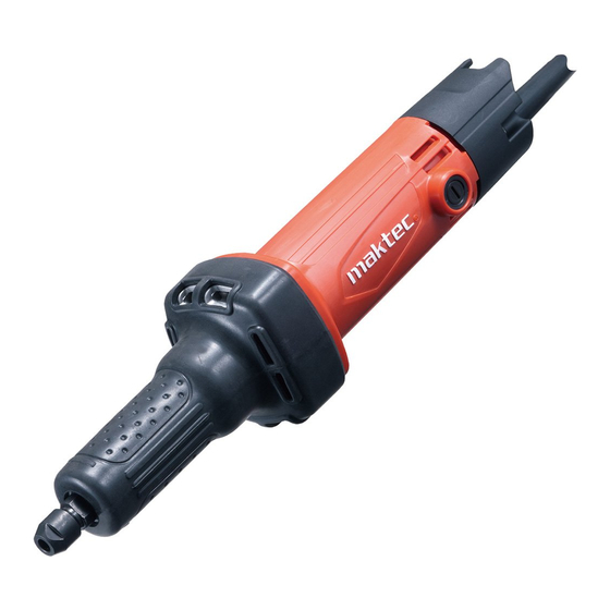
MT912
Die Grinder
Current (A)
Cycle (Hz)
4.6
50/60
4.2
50/60
2.3
50/60
2.2
50/60
2.1
50/60
¹=rpm
ˉ
: mm (")
2
: kg (lbs)
3
Continuous Rating (W)
Input
480
---
480
480
480
6mm or 1/4"
33,000
20 (13/16)
Double insulation
2.0 (6.6)
1.4 (3.1)
PRODUCT
L
H
W
Dimensions: mm (")
Length (L)
350 (13-3/4)
Width (W)
75 (2-15/16)
Height (H)
75 (2-15/16)
Max. Output (W)
Output
140
140
140
140
140
P 1/ 1
380
380
380
380
380
Advertisement
Table of Contents

Related Manuals for Makita Maktec MT912


Summary of Contents for Makita Maktec MT912
- Page 1 ECHNICAL INFORMATION PRODUCT P 1/ 1 Model No. MT912 Description Die Grinder ONCEPT AND MAIN APPLICATIONS Model MT912 has been developed as the cosmetic change model of maktec die grinder MT911. Dimensions: mm (") Its main features are: • Industrial performance and durability at less expense Length (L) 350 (13-3/4) •...
-
Page 2: Necessary Repairing Tools
P / 1 epair CAUTION: Repair the machine in accordance with “Instruction manual” or “Safety instructions”. [1] NECESSARY REPAIRING TOOLS Code No. Description Use for 1R031 Bearing setting pipe 28-20.2 mounting Ball bearing 6001ZZ to Barrel 1R045 Gear extractor (large) removing/mounting Ball bearing 6001ZZ from/to Spindle 1R232 Pipe 30... - Page 3 P / 1 epair [3] DISASSEMBLY/ASSEMBLY [3] -1. Barrel Section DISASSEMBLING (1) Remove Insulation cover from Barrel if the cover is used. (2) Disassemble Coupling and Bearing retainer from Barrel as drawn in Fig. 2. Fig. 2 1. Unscrew four 4x25 Tapping screws, 2.
- Page 4 P 4/ 11 epair [3] DISASSEMBLY/ASSEMBLY [3] -1. Barrel Section (cont.) DISASSEMBLING (3) Spindle section is now removed from Barrel as drawn in Fig. 3. Fig. 3 1. Put Barrel on 1R232. And then remove Spindle by pressing 2. Remove Ball bearing 629ZZ from Barrel 1R282 with Arbor press.
- Page 5 P 5/ 11 epair [3] DISASSEMBLY/ASSEMBLY [3] -1. Barrel Section (cont.) ASSEMBLING (1) Assemble Spindle section as drawn in Fig. 4. (2) Assemble Ball bearing 629ZZ to Barrel, and then assemble the Spindle section to Barrel. (Fig. 5) (3) Assemble Flat washer 18, Felt ring 17 and Bearing retainer to Barrel as drawn in Fig. 6. Fig.
- Page 6 P 6/ 11 epair [3] DISASSEMBLY/ASSEMBLY [3] -1. Barrel Section (cont.) ASSEMBLING (4) Assemble Barrel to Motor housing. (Fig. 7) Note in Assembling: When Barrel section is assembled to Motor housing, Rotation direction mark of Barrel must be positioned on the same side of Switch knob. (5) Mount Insulation cover to Barrel if the cover is used.
- Page 7 P 7/ 11 epair [3] DISASSEMBLY/ASSEMBLY [3] -2. Armature (cont.) DISASSEMBLING (2) Disassemble Armature section. (Fig. 10) Fig. 10 1. Remove Labyrinth 2. Remove Ball bearing 629ZZ with 1R269. rubber ring 19 by hand. And then, remove Insulation washer. 1R269 Ball bearing 629ZZ Labyrinth...
-
Page 8: Circuit Diagram
P 8/ 11 ircuit diagram Fig. D-1 Color index of lead wires' sheath Black Blue Brown Clear White Fig. R Fig. F Correct Wrong Field Lead Wire (black) Field Lead Wire (white) Field Field maktec logo maktec logo Motor housing Motor housing Brush Holder's Brush Holder's... -
Page 9: Wiring Diagram
P 9/ 11 iring diagram Motor housing of Rear cover side Pass Field lead wires (black and white) through the holes of Motor housing. Insert the grounding terminal of noise suppressor's lead wire deeply into the hole of Motor housing. Install Noise suppressor to the space painted with gray color in Fig. -
Page 10: Support Section
P 10/ 11 iring diagram Support section Install Terminal block and Switch to Support. (Fig. D-4) Fig. D-4 Terminal block Switch Support Switch Terminal block Left Noise suppressor Bottom Fig. D-5 Left side view Terminal block Switch Connecting terminal Connect Connecting terminal to Switch as follows. -
Page 11: Right Side View
P 11/ 11 iring diagram Support section Switch Right Terminal block Noise suppressor Bottom Fig. D-6 Right side view Fix the following lead wires with Lead wire holder. * Field lead wire (black) * Noise suppressor's lead wire for connecting to Terminal block Lead wire holder Terminal block Field lead wire...