Advertisement
Quick Links
T
ECHNICAL INFORMATION
Model No.
Description
C
ONCEPT AND MAIN APPLICATIONS
These maktec brand angle grinders MT92A and MT92B have been
designed for price competitive markets.
New maktec design is employed to eliminate white printing
and polygonal line from maktec logo/ elastomer from handle
for the cost effectiveness.
S
pecification
Voltage (V)
220
230
240
Specification
Wheel size: mm (")
No load speed: min.
Protection against electric shock
Power supply cord: m (ft)
Weight according to
EPTA-Procedure 01/2003*: kg (lbs)
* with Wheel cover, Inner flange, Lock nut, and Side grip
S
tandard equipment
Lock nut wrench 35 ...................... 1
Grip 36 complete .......................... 1
Note: The standard equipment for the tool shown above may vary by country.
O
ptional accessories
No
MT92A, MT92B
Angle Grinders 180mm (7"), 230mm (9")
Current (A)
Cycle (Hz)
10.5
10.0
9.6
Model No.
Diameter
Hole diameter
Max. thickness
¹
rpm
ˉ
=
Continuous Rating (W)
Input
50/60
2,200
50/60
2,200
50/60
2,200
MT92A
180 (7)
22.23 (7/8)
6 (1/4)
8,500
Double insulation
2.0 (6.6)
5.0 (11.0)
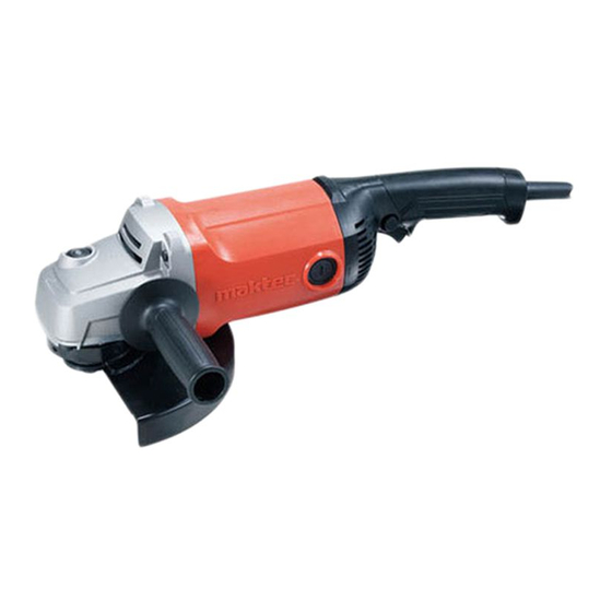
L
H
The above image
W
is Model MT92A.
Dimensions: mm (")
MT92A
Length (L)
439 (17-1/4)
Width (W)
200 (7-7/8)
Height (H)
141 (5-9/16)
Max. Output (W)
Output
1,700
1,700
1,700
MT92B
230 (9)
22.23 (7/8)
6 (1/4)
6,600
Double insulation
2.0 (6.6)
5.3 (11.6)
PRODUCT
P 1/ 9
MT92B
250 (9-7/8)
2,900
2,900
2,900
Advertisement

Related Manuals for Makita Maktec MT92A


Summary of Contents for Makita Maktec MT92A
- Page 1 ECHNICAL INFORMATION PRODUCT P 1/ 9 Model No. MT92A, MT92B Description Angle Grinders 180mm (7"), 230mm (9") ONCEPT AND MAIN APPLICATIONS These maktec brand angle grinders MT92A and MT92B have been The above image designed for price competitive markets. is Model MT92A. Dimensions: mm (") New maktec design is employed to eliminate white printing and polygonal line from maktec logo/ elastomer from handle...
- Page 2 Round bar for Arbor 8-50 1R269 Bearing extractor removing Ball bearings [2] LUBRICATION Apply Makita grease N No.1 to the following portions designated with the black triangle to protect parts and product from unusual abrasion. Item No. Description Portion to lubricate...
- Page 3 P 3/ 9 epair [3] DISASSEMBLY/ASSEMBLY [3]-2. Small spiral bevel gear, Armature, Ball bearings 6201DDW and 629ZZ DISASSEMBLING (1) Separate Gear housing from Motor housing and remove Bearing box section from Gear housing. ( Fig. 2) Fig. 2 1. Remove Brush holder caps and Carbon brushes from Motor housing, 2.
- Page 4 P 4/ 9 epair [3] DISASSEMBLY/ASSEMBLY [3]-2. Small spiral bevel gear, Armature, Ball bearings 6201DDW and 629ZZ (cont.) DISASSEMBLING (3) Disassemble Ball bearings 6201DDW and 629ZZ. (Fig. 4) Note: The removed Armature and small Spiral bevel gear are employed as repairing tools when removing Ball bearing 6201DDW from Gear housing.
- Page 5 P 5/ 9 epair [3] DISASSEMBLY/ASSEMBLY [3]-3. Large spiral bevel gear, Ball bearing 6202DDW and Ball bearing 607ZZ DISASSEMBLING (1) No need to separate Motor housing from Gear housing. Separate Bearing box section from Gear housing, and remove Ball bearing 607ZZ and Ring spring 13 from Spindle. (Fig. 6) Fig.
- Page 6 P 6/ 9 epair [3] DISASSEMBLY/ASSEMBLY [3]-3. Large spiral bevel gear, Ball bearing 6202DDW and Ball bearing 607ZZ (cont.) DISASSEMBLING (3) Disassemble Ball bearing 6202DDW. (Fig. 8) Fig. 8 1. Remove Bearing retainer 2. Put Bearing box onto Turn base of Arbor press with its Ball bearing by unscrewing three M4x13 mounting side faced to Turn base.
- Page 7 P 7/ 9 epair [3] DISASSEMBLY/ASSEMBLY [3]-4. Shaft Lock DISASSEMBLING (1) Remove Bearing box section from Gear housing complete. (Fig. 2) (2) Disassemble Shaft lock mechanism as drawn in Figs. 9 and 10. Fig. 9 Fig. 10 Set the machine on 1R350, then apply 1R268 to Shoulder pin 5 Release 1R268 from Pin cap carefully through the small Hole on Pin cap, and then tap 1R268 with so that Pin cap does not be slung by...
-
Page 8: Circuit Diagram
P 8/ 9 ircuit diagram Fig. D-1 MT92A, MT92B Color index of lead wires' sheath Black Blue White Brown Field viewed from Noise Noise suppressor is not used Commutator side suppressor for some countries. Field Handle set (L) side Handle set (R) side Switch This Lead wire is white This Lead wire is black... - Page 9 P 9/ 9 iring diagram Fig. D-3 Wiring to Switch Connect connectors for Field lead wires Connect Noise suppressor’s lead wires to Switch terminal to Switch terminals of Handle set (L) side from the same direction as Field lead wires while facing while facing their Wire connecting portions their wire connecting portions to Handle set(L) side.