
Related Manuals for GE T2100


Summary of Contents for GE T2100
- Page 1 GE Healthcare T2100 Treadmill Service Manual 2021403-120 Revision F T2100 Treadmill English © 2012-2016 General Electric Company. All Rights Reserved.
- Page 2 Publication Information The information in this manual applies only to T2100 Treadmill product codes SK2 and SM9. It does not apply to earlier product versions. Due to continuing product innovation, specifications in this manual are subject to change without notice.
- Page 3 Probeer de apparatuur niet te onderhouden voordat deze service manual geraadpleegd en begrepen is. • Indien deze waarschuwing niet wordt opgevolgd, zou het onderhoudspersoneel, de gebruiker of een patiënt gewond kunnen raken als gevolg van een elektrische schok, mechanische of andere gevaren. 2021403-120F T2100 Treadmill...
- Page 4 Keine Wartung durchführen, ohne diese Serviceanleitung gelesen und verstanden zu haben. • Bei Zuwiderhandlung kann es zu Verletzungen des Kundendiensttechnikers, des Anwenders oder des Patienten durch Stromschläge, mechanische oder sonstige Gefahren kommen. ΠΡΟΕΙΔΟΠΟΙΗΣΗ Το παρόν εγχειρίδιο σέρβις διατίθεται στα αγγλικά μόνο.
- Page 5 Ez a szerviz kézikönyv kizárólag angol nyelven érhető el. FIGYELMEZTETÉS • (HU) Ha a vevő szerviz ellátója angoltól eltérő nyelvre tart igényt, akkor a vevő felelőssége a fordítás elkészíttetése. • Ne próbálja elkezdeni használni a berendezést, amíg a szerviz kézikönyvben leírtakat nem értelmezték és értették meg.
- Page 6 Este manual de assistência técnica só se encontra disponível em inglês. (PT-BR) • Se o serviço de assistência técnica do cliente não for GE, e precisar de outro idioma, será da responsabilidade do cliente fornecer os serviços de tradução. •...
- Page 7 Če ponudnik storitve stranke potrebuje priročnik v drugem jeziku, mora stranka zagotoviti prevod. • Ne poskušajte servisirati opreme, če tega priročnika niste v celoti prebrali in razumeli. • Če tega opozorila ne upoštevate, se lahko zaradi električnega udara, mehanskih ali drugih nevarnosti poškoduje ponudnik storitev, operater ali bolnik. 2021403-120F T2100 Treadmill...
- Page 8 Không tuân thủ những cảnh báo này có thể dẫn đến các tổn thương cho người thực hiện sửa chữa, người vận hành hay bệnh nhân, do sốc điện, các rủi ro về cơ khí hay các rủi ro khác. 2021403-120F T2100 Treadmill 29 November 2016...
-
Page 9: Table Of Contents
Connection Panel..................35 Installation Tools Required................... 37 Safe Handling Guidelines ................37 Installation Checklist ................38 Electrical Safety Tests ................39 2021403-120F T2100 Treadmill... - Page 10 Check T2100 Treadmill Level ........
- Page 11 Power Down ................... 77 T2100 Treadmill Diagnostic Utility (TDU)........... 78 Overview of the TDU Application Interface .
- Page 12 Field Replaceable Units ................131 Technical Specifications Performance Specifications ..............135 Physical Specifications................135 Power/Environmental Specifications ............136 Safety ...................... 136 Environmental..................137 Electromagnetic Compatibility (EMC) Electromagnetic Emissions ..............140 Electromagnetic Immunity..............140 Electromagnetic Immunity..............141 Separation Distance................143 Exceptions....................144 2021403-120F T2100 Treadmill...
- Page 13 Compliant Cables ..................145 2021403-120F T2100 Treadmill...
- Page 14 2021403-120F T2100 Treadmill...
-
Page 15: Introduction
This section provides information for the correct use of this manual. Keep this manual with the equipment at all times and periodically review it. You should request training assistance from GE Healthcare, if needed. Intended Audience This manual is intended for the person who uses, maintains, or troubleshoots this equipment. -
Page 16: Regulatory And Safety Information
Disregarding the safety information provided is considered abnormal use of this device and could result in injury, loss of data, and void any existing product warranties. Safety Conventions A Hazard is a source of potential injury to a person, property, or the system. 2021403-120F T2100 Treadmill... -
Page 17: Safety Hazards
To avoid electric shock or device malfunction, liquids must not be allowed to enter the device. WARNING: EQUIPMENT MALFUNCTION — Replace only with the same type and rating of fuse. WARNING: EQUIPMENT MALFUNCTION — No modification of this equipment is allowed. 2021403-120F T2100 Treadmill... - Page 18 DO NOT rapidly change treadmill speed and/or grade during a stress test. WARNING: TREADMILL CHANGES — DO NOT place feet under the treadmill during operation or while decreasing the treadmill grade to avoid injury. 2021403-120F T2100 Treadmill...
- Page 19 This equipment is suitable for connection to public mains as defined in CISPR 11. CAUTION: SUPERVISED USE — This equipment is intended for use under the direct supervision of a licensed health care practitioner. Make sure all users are under the direct supervision of a licensed health care practitioner. 2021403-120F T2100 Treadmill...
-
Page 20: Classification Of Medical Device
EMC and must be installed and put into service according to the EMC information stated in the Electromagnetic Compatibility appendix of the Service and/or Operator’s manual. Changes or modifications to this system not expressly approved by GE Healthcare could cause EMC issues with this or other equipment. Mains power should be a standard commercial or hospital environment. -
Page 21: Responsibility Of The Manufacturer
If the interference stops, it was most likely caused by the device or system. Responsibility of the Manufacturer GE Healthcare is responsible for the safety, reliability, and performance of hardware supplied by GE Healthcare only if the following conditions are met: • Assembly operations, extensions, readjustments, modifications, or repairs are performed by persons authorized by GE Healthcare. -
Page 22: Product And Packaging Information
Introduction Product and Packaging Information This section identifies the following: Hardware Label Locations 2021403-120F T2100 Treadmill... - Page 23 • Regulatory compliance • Country of Origin • EC Representative information Located on the rear connector panel, this label contains the cautionary, disposal, and regulatory information. See “Symbol Descriptions” on page for more information on the symbols. 2021403-120F T2100 Treadmill...
- Page 24 There may be specific warnings or precautions associated with the device that are not otherwise found on the label. Consult the accompanying documentation for more information about safely using this device. Consult Instructions for Use Consult the operating instructions. 2021403-120F T2100 Treadmill...
- Page 25 (WEEE) Indicates this equipment contains electrical or electronic components that must not be disposed of as unsorted municipal waste but collected separately. Contact an authorized representative of the manufacturer for information concerning the decommissioning of your equipment. 2021403-120F T2100 Treadmill...
- Page 26 Indicates the manufacturer's serial number. Catalog or Orderable Part Number Indicates the manufacturer's catalog or part number. Authorized Representative in the European Community Indicates the name and address of the authorized representative in the European Community for this device. 2021403-120F T2100 Treadmill...
- Page 27 Mass of the Machinery Configuration For machinery presenting hazards due to its mobility: this symbol expresses mass of the machinery configuration in kilograms. General symbol for recovery/recyclable T 0.5AL, 250V Time Lag, 0.5 Amp, Low breaking capacity, 250 Vac rated fuse 2021403-120F T2100 Treadmill...
-
Page 28: Equipment Identification
Equipment Identification The Equipment Identification tag that contains the Product Code and Serial Number is located on the lip of the connection panel (on the back of the T2100 Treadmill). Product Label The product label is laid out in the following format. Depending on the product, the label may vary slightly in format, but it contains the same information. -
Page 29: Serial Number Format
Fiscal Week Two-digit code identifying the week the device was Manufactured manufactured. Values range from 01 to 52. GE Healthcare's fiscal weeks correspond to the calendar week. For example, 01 = first week in January. Product Sequence Four-digit number identifying the order in which this device was manufactured. -
Page 30: Service Information
Refer equipment servicing to GE Healthcare authorized service personnel only. Any unauthorized attempt to repair equipment under warranty voids that warranty. It is the user’s responsibility to report the need for service to GE Healthcare or to one of their authorized agents. -
Page 31: Equipment Overview
Treadmill has fewer moving parts than other treadmills, built-in self-calibration, and replaceable assemblies. Intended Use The T2100 Treadmill is intended for use with any one of the several GE Healthcare exercise testing systems for administering a controlled exercise load during a diagnostic stress test. -
Page 32: Drive Controller System
The T2100 Treadmill can accommodate a weight capacity up to 450 lbs. Elevation System The elevation system uses a rack and pinion operation to raise and lower the T2100 Treadmill rather than jack screws and chains. The elevation motor attaches to a small gearbox that connects to the pinion shaft. -
Page 33: Side View
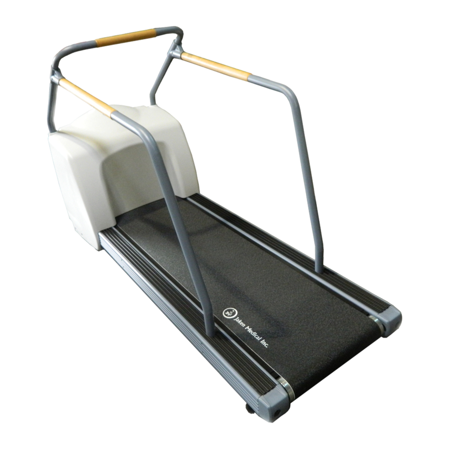
Equipment Overview Side View Item Description Handrails Emergency Stop (ESTOP) Shroud Elevation racks and wheels Level adjusting feet Walking belt 2021403-120F T2100 Treadmill... -
Page 34: Rear View
Equipment Overview Rear View Item Description Standing feet For support when standing the T2100 Treadmill upright on this end. Connection Panel 2021403-120F T2100 Treadmill... -
Page 35: Connection Panel
Equipment Overview Connection Panel The following illustration describes the connectors on the connection panel of the T2100 Treadmill, and identifies the general location of the serial number. Item Description RS232 Serial Port RS422 Serial Port Calibration Button The serial number sticker is affixed to the right inside lip of the connection panel. - Page 36 Equipment Overview 2021403-120F T2100 Treadmill...
-
Page 37: Installation
T2100 Treadmill. Safe Handling Guidelines The T2100 Treadmill ships preset with an approximate 2% grade. This slight elevation provides for free wheel movement and prevents the shroud from scraping the floor. 2021403-120F... -
Page 38: Installation Checklist
Installation If you are moving the T2100 Treadmill after it has been in operation, use the controlling equipment to set the grade to approximately 7%. Then remove power and disconnect all cables to the T2100 Treadmill before moving the unit. -
Page 39: Electrical Safety Tests
The T2100 Treadmill ships completely assembled except for the handle set and the emergency stop switch. As recommended by the American Heart Association Exercise Standards (Special Report, Vol 82, No 6), the T2100 Treadmill should have front and side rails installed 2021403-120F T2100 Treadmill... -
Page 40: Pre-Assembly Inspection
Remove the screws on the shroud back and remove the back panel and visually inspect the following: Drive Belt – The drive belt is correctly adjusted at the factory, but may have changed during shipping. Before operating the T2100 Treadmill, verify the tension of the drive belt. See “Drive Belt Adjustments” on page for proper tension tolerances. - Page 41 See item 4 in the drawing at the beginning of this section for designation of right side and left side handrails. Attach the side rails to the front rail with the mated T-brackets. Tighten the two T-bracket bolts with the Allen wrench. 2021403-120F T2100 Treadmill...
-
Page 42: Install Emergency Stop Switch
NOTE: The emergency stop switch must be installed and the ESTOP cable plugged in to the T2100 Treadmill connection panel for the T2100 Treadmill to operate. If the ESTOP is not installed, the T2100 Treadmill will not operate. Attach the two clamp pieces to the assembled, latching emergency stop switch. -
Page 43: Power Cord And Plug
This test verifies that there is continuity (less than 100 mΩ resistance) between all the exposed metal surfaces, which have the potential to become energized, and the ground prong on the mains AC power cord. Look for an exposed metal screw, or, if the 2021403-120F T2100 Treadmill... -
Page 44: Connect Controlling Devices
COM 1, COM 2, COM C or COM D. The CASE RSS modem requires the use of either COM 1 or COM 2. Move the T2100 Treadmill interface cable to COM C or COM D only as necessary. -
Page 45: Secure The Cables
With the belt moving at a relatively high speed, press the emergency stop switch. The T2100 Treadmill belt will stop promptly but the belt will not lock, allowing for removal of foreign objects. To release the switch, turn the button 1/4 turn. - Page 46 Calibration Button ON/OFF Switch Turn the T2100 Treadmill ON/OFF switch to the On position. Continue to hold the Calibration button until the T2100 Treadmill starts changing elevation. NOTE: Hold the Calibration button for at least 4 seconds. May be up to 25 seconds only for a T2100 processor board that has never been calibrated.
-
Page 47: Check T2100 Treadmill Level
Use the controlling equipment to verify the T2100 Treadmill elevation is 0.0%. Check the T2100 Treadmill level with a carpenter’s level. If the T2100 Treadmill is uneven, adjust the feet at the rear of the T2100 Treadmill until it is level. -
Page 48: Leakage Test Diagrams
These diagrams show only a representation of how a typical leakage current tester functions. Follow the instructions provided with the leakage current tester that you use. Test #1 Ground-Wire-Leakage-to-Ground Test #2 Chassis-Leakage-to-Ground (Exposed Chassis) Make sure the UUT is in the ON state. 2021403-120F T2100 Treadmill... -
Page 49: Functional Checkout
Installation Functional Checkout Functional Checklist Perform each of the functional checkout procedures below and verify that the T2100 Treadmill passes each procedure before operating this treadmill. Procedure Indicate If Failed, perform the following: Indicate Pass/Fail Pass/Fail AC Power Check. Contact site electrician to correct. - Page 50 Belt Tracking Adjustment” on page the walking board? Check the walking belt Adjust the belt tension. tightness. Get on the T2100 See “Walking Belt Tension Treadmill and try to stop the Adjustment” on page 55. belt at a slow speed with your feet, holding onto the handrail.
- Page 51 Communicate with Host Can Host control elevation Check that interface cable is and speed? properly connected. Replace interface cable. Use the T2100 Treadmill Diagnostic Utility (TDU) to help troubleshoot the problem. See “T2100 Treadmill Diagnostic Utility (TDU)” on page Noise and Vibration “Location of Major...
-
Page 52: Double-Check Handles
Request Biomed to perform Leakage Test. Was leakage test performed “Equipment Assembly” on page by Biomed and did it pass? Double-Check Handles Check to make sure all handles are secure. Verify that all screws on the handles are fastened securely. 2021403-120F T2100 Treadmill... -
Page 53: Maintenance
A regular equipment maintenance program helps prevent unnecessary equipment and power failures and also reduces possible health hazards. To help you establish a systematic maintenance routine, GE Healthcare recommends that you periodically perform the maintenance and test procedures described in this manual, including: •... -
Page 54: Inspection And Cleaning
It is not unusual for the T2100 Treadmill belt to move slightly off center while a person with a heavy gait is exercising. A properly adjusted belt re-centers itself when the person steps off the T2100 Treadmill. -
Page 55: Walking Belt Tension Adjustment
Use the controlling equipment to set the walking belt speed to 3 – 5 km/h (2 – 3 mph). Hold on to the handrails, mount the T2100 Treadmill, and begin walking at a normal pace. Hold on to the handrails tightly and step harder and heavier onto the walking belt, adding more pressure and weight. - Page 56 Increase the speed to 16 – 19 km/h (10 – 12 mph) and verify that the belt continues to track in the center. Check the walking belt tension again to verify that it has not been loosened when adjusting the tracking. See “Walking Belt Tension Adjustment” on page 2021403-120F T2100 Treadmill...
-
Page 57: Theory Of Operation
Theory of Operation T2100 Treadmill Block Diagram 2021403-120F T2100 Treadmill... -
Page 58: Power Board (Pcb) Theory
Initial Board Conditions The power board initial conditions are all at 0V. Power Input Requirements The T2100 Treadmill is used on single phase AC. The specific power ratings are 200-240VAC, 50-60 Hz, 16A. Power Distribution/Isolation The power board receives 200 to 240VAC power (nominal 220V). The isolation transformer supplies 12V to two switching regulators. -
Page 59: Local Ride-Through Power
These capacitors provide 3.3 Farads of capacitance that give the processor board power to logically power down activities in case of a loss of power to the T2100 Treadmill. Processor Board Connectors The power board has two connectors that directly interface with the processor board. -
Page 60: Power Board Input/Output Signal Requirements
Digital Ground Supply J1–3 EN_ELEV LOGIC PULSE Elevation Enable Control J1–4 DGND Digital Ground Supply J1–5 LIMIT* LOGIC PULSE Limit Switch Feedback J1–6 DGND Digital Ground Supply J1–7 ELEV_FB Pot Elevation Feedback J1–8 DGND Digital Ground Supply 2021403-120F T2100 Treadmill... - Page 61 COMMENT J6–1 220V_UP 50-60 Power Up Elevation J6–2 J6–3 220V_DN 50-60 Power Down Elevation J6–4 220V_UP 50-60 Power Up Elevation J6–5 J6–6 220V_DN 50-60 Power Down Elevation J6–7 J6–8 J6–9 J6–10 220V_ELEV 50-60 220V Power to Motor 2021403-120F T2100 Treadmill...
- Page 62 TYPE FREQ COMMENT J10–1 Ground LINE J11–1 50-60 Line Power Out J12–1 LINE 50-60 Line Power Out J13 AC Power to +24V Power Supply PIN # NAME TYPE FREQ COMMENT J13–1 LINE 50-60 Line Power Out J13–2 2021403-120F T2100 Treadmill...
-
Page 63: Processor Board (Pcb) Theory
• Serial control links • I/O circuitry The I/O circuitry receive inputs from a stress system controller along with feedback from the T2100 Treadmill sensors to control the elevation and drive relays located on the power board. Power Distribution The processor board receives two sources of 5-volt power from the power board: an isolated supply, and a non-isolated supply. -
Page 64: Reset Generator
128 KB Flash EPROM. The MC9s12DG128 addresses its memory internally. The processor handles all the I/O, including two serial channels, 4 analog inputs, and digital inputs and outputs to control the T2100 Treadmill grade, speed, calibration and ESTOP processes. -
Page 65: Rs-232/422 Interfaces
250 VAC. Operation The processor board’s main task is to monitor the proper T2100 Treadmill operation by testing selected variables from the system. In case of any variable operating out of specs, the firmware will first detect the event, then log it, and finally stop any further operation. -
Page 66: Self-Calibration
T2100 processor board that has never been calibrated. ESTOP In order to operate the T2100 Treadmill, the ESTOP plug must be attached to its receptacle on the processor board. Failure to perform this action will initiate a RESET* sequence on the microcontroller disabling any further power up sequence. -
Page 67: Processor Board Input/Output Signal Requirements
PIN # NAME TYPE FREQ COMMENT J1–1 J1–2 J1–3 RXLO RS422 9600bps Host RS422 Serial Comm J1–4 ISOGND ISO GND Supply J1–5 TXLO RS422 9600bps Host RS422 Serial Comm J1–6 RXHI RS422 9600bps Host RS422 Serial Comm 2021403-120F T2100 Treadmill... - Page 68 ISOGND ISO GND Supply J3–2 +5V ISO ISO Power Supply J3–3 J3–4 RXLO RS422 9600bps Host RS422 Serial Comm J3–5 RXHI RS422 9600bps Host RS422 Serial Comm J3–6 +VUNREG ISO Power Supply J3–7 ISOGND ISO Gnd Supply 2021403-120F T2100 Treadmill...
- Page 69 FREQ COMMENT J6–1 +5V ISO ISO Power Supply J6–2 ISOGND ISO Gnd Supply J6–3 +VUNREG ISO Power Supply J8 BDM Connector PIN # NAME TYPE FREQ COMMENT J8–1 BKGND LOGIC 9600bps uC Serial Comm IN/OUT J8–2 J8–3 2021403-120F T2100 Treadmill...
-
Page 70: Drive Controller Theory
Y-connected windings with six power switches. Each phase consists of two windings in series, spaced 120 electrical degrees apart. Each phase can be energized in either direction by turning on two of the six power devices. This arrangement of switches 2021403-120F T2100 Treadmill... -
Page 71: Motor Torque
The orange wire from the side of the enclosure is connected to the sheetmetal enclosure and should be connected to the designated terminal on the power terminal block. Do not connect this wire to the T2100 Treadmill frame which would cause a safety hazard. - Page 72 Theory of Operation 2021403-120F T2100 Treadmill...
-
Page 73: Troubleshooting
Troubleshooting Quickcheck Items Speed and Elevation Table Use the quickcheck chart below to identify the probable causes for problems relating to stops and hesitations for elevation, speed, and a combination of elevation and speed. 2021403-120F T2100 Treadmill... -
Page 74: Emergency Stop Switch Verification
Emergency Stop Switch Verification Verify that the emergency stop switch is installed and connected. The emergency stop switch (ESTOP) must be installed for the T2100 Treadmill to operate. If the ESTOP is not installed, the T2100 Treadmill will not operate. -
Page 75: Activating Burn-In
Make sure you monitor the site at all times. Make sure there are no customers or patients on or near the T2100 Treadmill during burn-in. To activate the burn-in mode, do the following: Remove controlling device (for example, CASE) cable or turn off the controlling device. -
Page 76: Visual Inspection
The burn-in mode can only be activated while the T2100 Treadmill is performing a self-calibration. Press the Calibration button again as soon as the T2100 Treadmill gets to the maximum height limit switch (maximum 30 seconds) and hold until the T2100 Treadmill elevation starts changing again (maximum 2 seconds). -
Page 77: Power Down
• Loose or missing components • Burn damage or smell of over-heated • Socketed components not firmly seated • PCB not seated properly in edge connectors • Solder problems: cracks, splashes on board, incomplete feed through, prior modifications or repairs 2021403-120F T2100 Treadmill... -
Page 78: T2100 Treadmill Diagnostic Utility (Tdu)
The TDU can be installed on an FE laptop, PC, or a CASE system and is used as an interface to retrieve error and event logs stored in the T2100 Treadmill flash memory. These event and error logs are used to help troubleshoot problems, and identify historical trends. -
Page 79: Tdu Application Error Definitions
Connect treadmill – A connection to the T2100 Treadmill will be established. This must be done before you can download a log file. The T2100 Treadmill characteristics (Type, Version, ...) are shown in the status line when the connection is done. -
Page 80: Download The Tdu
The event log may have to be retrieved again. Download the TDU The TDU application is available for download from GE service support portals. Follow the instructions below to access the nearest service portal. NOTE: Customers can call Technical Support to receive the utility via email. -
Page 81: Launch Tdu And Retrieve Event And Error Logs
FE laptop and the DB9 connector on the T2100 Treadmill, and launch TDU. • For CASE – Make sure the CASE is connected to the T2100 Treadmill using the standard RS232 DB9 interface cable (pn 700609-002), and launch TDU. -
Page 82: Tdu Troubleshooting Tables And Status Leds
(SDT) is set to January 1, 2050, 0:00:00 and is then stored into the flash memory. When power is applied to the T2100 Treadmill, the SDT is set to the saved SDT in the flash memory. While power is applied, the system updates the SDT every second. -
Page 83: Processor Board Status Leds
When the drive error is cleared, the LED is off. Also, the LED will turn on when burn-in is activated. During the burn-in cycle, the LED will flash rapidly for 100ms every time the belt speed increases. 2021403-120F T2100 Treadmill... -
Page 84: Tdu Troubleshooting Table
Determine the error codes being reported by TDU and use the table below to help troubleshoot the cause, and identify the repair. Some TDU event/error codes also have detail descriptions breaking out specific causes within the event/error code. 2021403-120F T2100 Treadmill... - Page 85 Belt Error Measures the drive motor RPM. (Halts Current Powercycle the T2100 Operation) Treadmill and monitor the T2100 Treadmill for reoccurrence of this error. (This may be an isolated incident.) Check for loose wiring and connections between the drive controller and the drive motor.
- Page 86 • <00> During Operation) calibration, the Powercycle the T2100 potentiometer Treadmill and monitor feedback did not the T2100 Treadmill for change while the reoccurrence of this error. elevation motor (This may be an isolated was running. incident.) • <01> During...
- Page 87 (149° F). (where XX equals Operation) the temperature in Remove power from the Celsius) T2100 Treadmill and allow to cool off. Power up the T2100 Treadmill and monitor the T2100 Treadmill for reoccurrence of this error. (This may be an isolated incident.)
- Page 88 Powercycle the T2100 Treadmill and monitor • <02> Could not the T2100 Treadmill for check for drive reoccurrence of this error. axis errors. (This may be an isolated incident.) • <03> Could not...
- Page 89 TDU Event / Definition and Check These Items Error Code Detail Description 0x06 Fatal Over-voltage Measures power into the T2100 Treadmill. (Halts Current Operation) Powercycle the T2100 Treadmill and monitor the T2100 Treadmill for reoccurrence of this error. (This may be an isolated incident.)
- Page 90 Troubleshooting Status TDU Event / Definition and Check These Items Error Code Detail Description 0x07 Fatal Under-voltage: Measures power into the T2100 Treadmill. (Halts Current • <00> Operation) Under-voltage Powercycle the T2100 detected while Treadmill and monitor system still the T2100 Treadmill for operating.
- Page 91 • <00> Not an error – occurred during Powercycle the T2100 calibration. Treadmill and monitor the T2100 Treadmill for • <01> Error – reoccurrence of this error. occurred during (This may be an isolated normal operation. incident.) Initiate the self-calibration feature.
- Page 92 Detail Description 0x0c Temperature Warning The ambient temperature inside Warning (*C)<XX> the e-box has reached 55° C (131° F). The T2100 Treadmill (where XX equals still operates correctly, but the temperature in this warning indicates that Celsius) something is causing the temperature to rise to near-fatal levels.
-
Page 93: Drive Controller Status Led
If an undervoltage trip occurs in conjunction with another error, the drive will flash the code of the additional error. See the troubleshooting table below for the event/error code and it’s corresponding red flashing LED. 2021403-120F T2100 Treadmill... -
Page 94: Tdu Troubleshooting Table For Drive Controller
Indicates the DC Bus voltage has trip exceeded the overvoltage level. Powercycle the T2100 Treadmill and monitor the T2100 Treadmill for reoccurrence of this error. (This may be an isolated incident.) Verify that the AC power supply voltage is correct. See “AC Line... - Page 95 Over-current trip Indicates Current has exceeded 300% of Drive Rated Current. Powercycle the T2100 Treadmill and monitor the T2100 Treadmill for reoccurrence of this error. (This may be an isolated incident.) Check the motor cables and drive controller connections for short circuits.
- Page 96 Powercycle the T2100 Treadmill and monitor the T2100 Treadmill for reoccurrence of this error. (This may be an isolated incident.) Check the wiring in the Feedback cable.
- Page 97 Allow the unit to cool. Increase ventilation and reduce ambient temperature. Powercycle the T2100 Treadmill and monitor the T2100 Treadmill for reoccurrence of this error. (This may be an isolated incident.) Determine if any TDU Troubleshooting Table errors...
- Page 98 Following error could also be the caused by encoder/resolver loss. Powercycle the T2100 Treadmill and monitor the T2100 Treadmill for reoccurrence of this error. (This may be an isolated incident.) Confirm that the motor is not overloaded or stalling.
- Page 99 Replace if out of specification. Verify input voltage to the treadmill is within range. Power-cycle the T2100 Treadmill and monitor the T2100 Treadmill for reoccurrence of this error. (This may be an isolated incident.) Replace the drive controller and drive motor.
-
Page 100: Power Supply Voltage Checks And Fuses
Undervoltage Trip Red and below the undervoltage level. Green Powercycle the T2100 Treadmill and monitor the T2100 Treadmill for reoccurrence of this error. (This may be an isolated incident.) Verify that the AC power supply voltage is correct. See “AC Line Voltage Test”... -
Page 101: Power Board Voltage Checks
Processor Board Voltage Check Test Points Power Board Voltage Checks Nominal Power Type Signal Name value Test range Test point Reference ISO Power +5V_ISO 5.1V ISOGND TP4 +/- 5% DGND 5.1V DGND TP2 Non-Isolated +/- 5% Power 2021403-120F T2100 Treadmill... - Page 102 Troubleshooting Power Board Voltage Check Test Points 2021403-120F T2100 Treadmill...
-
Page 103: Power Board Fuse Locations
The 20A and 2.5A fuses are located on the power board. Remove the cover of the e-box to access and change these fuses. The 1/2A fuses are accessed at the connector panel on the back of the T2100 Treadmill. 2021403-120F... - Page 104 Troubleshooting 2021403-120F T2100 Treadmill...
-
Page 105: Fru Replacement
• Stop the treadmill by using the controlling device or emergency stop switch when appropriate. • Place the ON/OFF switch to the OFF (O) position. • Disconnect from supply mains by unplugging power cord from wall and T2100. 2021403-120F T2100 Treadmill... -
Page 106: Leakage Tests
“Performing Leakage Tests” on page Shroud Removal To remove the T2100 Treadmill shroud for the internal visual inspection or for service: • Disconnect the power cord from the rear connector panel. • Remove the screws on the shroud back and remove the back panel. -
Page 107: Location Of Major Sub-Assemblies
ELECTRICAL SHOCK. Electrical shock hazard between chassis ground and isolated (“floating”) ground when power is applied. Unplug the unit from the power source before proceeding. Item Description Drive Controller Flywheel Elevation Motor Worm Gear Elevation Limit Switch 2021403-120F T2100 Treadmill... -
Page 108: Front Roller Replacement
Turn the ON/OFF switch to the OFF position, disconnect the power cord from the wall outlet, and remove the shroud. Loosen the drive belt and remove it from the sprocket. See “Drive Motor Replacement” on page 113 for steps relative to loosening the drive belt. 2021403-120F T2100 Treadmill... - Page 109 Loosen the walking belt tension screws on the end of the T2100 Treadmill. Arrows point to location of tension screws. On the drive-belt side of the T2100 Treadmill, remove the 3 bolts fastening the walking belt drive gear to the roller.
-
Page 110: Rear Roller Replacement
Turn the ON/OFF switch to the OFF position and disconnect the power cord from the wall outlet. Remove the walking belt tension screws on the end of the T2100 Treadmill and remove the end caps. Arrows point to location of tension screws. -
Page 111: Walking Belt And Board Replacement
You do not have to remove either roller to replace the belt. Loosen the tension bolt on the left end cap. Remove the tension bolt and the right end cap. Loosen the keeper nut on the right foot, and unscrew and remove the right foot. 2021403-120F T2100 Treadmill... -
Page 112: Walking Board Replacement Instructions
FRU Replacement On the front right side of the T2100 Treadmill, remove the eight, 1/2 inch bolts that hold the frame’s sliding bracket in place. Item Descriptions Sliding Bracket Bolts (4 on each side) Sliding Bracket Slide the bracket left, into the frame. -
Page 113: Drive Motor Replacement
FRU Replacement Place the new walking board on the T2100 Treadmill with the beveled edges facing down, towards the rollers. Secure the new walking board to the bed assembly with the 8 Allen-head screws. Replace the walking belt. Use the reverse order used to remove the walking belt as described in “Walking Belt Replacement Instructions”... - Page 114 Lower the motor using the 2 drive belt tension adjustment bolts until the drive belt can be removed from the sprocket. Item Description Drive Belt Tension Adjustment Bolts Upper Motor Mounting Bolts (2) Sprocket Drive Belt Lower Mounting Bolts (2 under the motor) 2021403-120F T2100 Treadmill...
- Page 115 Remove the hub when it is loose of the motor shaft. Remove the hub key and the flywheel. NOTE: The flywheel weighs 15 lbs. (6.8 k) 2021403-120F T2100 Treadmill...
-
Page 116: Drive Belt Replacement And Adjustments
“Drive Belt Adjustments” on page 117 “Adjust Drive Belt Tracking” on page 118. Calibrate the T2100 Treadmill. See “Self-Calibration” on page Drive Belt Replacement and Adjustments Replace the Drive Belt Turn the ON/OFF switch to the OFF position, disconnect the power cord from the wall outlet, and remove the shroud. -
Page 117: Drive Belt Adjustments
There are two drive belt tension adjustment bolts above the DC motor. Tighten these 1/2-inch bolts to adjust the drive belt tension (clockwise to tighten). Item Description Drive Belt Adjustment Bolts (2) Upper Motor Mounting Bolts (2) Lower Motor Mounting Bolts (2) (Located under the motor.) 2021403-120F T2100 Treadmill... - Page 118 Because of this design, the drive belt will always track to the left side of the top sprocket (and this is normal) but should track down the middle of the lower sprocket. If the drive belt tracks off center on the lower sprocket, adjust the position of the top 2021403-120F T2100 Treadmill...
-
Page 119: Elevation Motor Replacement
Arrows point to the location of the two elevation shaft collar set screws. NOTE: It is important to raise the T2100 Treadmill to give access to an elevation motor mounting bolt later in this procedure. Turn the ON/OFF switch to the OFF position, disconnect the power cord from the wall outlet, and remove the shroud. - Page 120 “Potentiometer Installation Procedure” on page 123 for procedures when installing the potentiometer. Replace the tie wraps for the elevation motor wiring harness. Calibrate the T2100 Treadmill. See “Self-Calibration” on page 2021403-120F T2100 Treadmill...
-
Page 121: Drive Controller Assembly
Disconnect all connectors from the drive controller. Remove the 4 nuts from the drive controller mounting bracket and remove the mounting bracket and drive controller from the T2100 Treadmill. Remove the 4 nuts from the drive controller fastening points. Remove the drive controller and replace with a new drive controller in reverse order. -
Page 122: Elevation Potentiometer Replacement
Orange wire earth/ground going to the ground terminal on the power board. Can be inverted with the other Gnd. Elevation Potentiometer Replacement Replace the Elevation Potentiometer Harness on T2100 Treadmills experiencing elevation hesitation and seeking problems or a faulty T2100 Treadmill stop condition during an elevation change. 2021403-120F T2100 Treadmill... -
Page 123: Elevation Potentiometer Harness Assembly Replacement
This must be done in order to maintain the 1–2 turns established in Step 4. Also be sure that the cables are toward the rear of the T2100 Treadmill. Attach the tube far enough on to the 2021403-120F... - Page 124 Power on the unit and run calibration to ensure proper operation of elevation system. Test the T2100 Treadmill using the CASE system (or other controlling device) to ensure the T2100 Treadmill is capable of reaching its lower and upper limits.
- Page 125 Step 5. See the “Potentiometer Removal Guidelines” below. Manually increase the elevation to a 25% grade and confirm that the 25.0 is displayed. Re-assemble the remaining components to complete the overall T2100 Treadmill assembly. 2021403-120F T2100 Treadmill...
- Page 126 The potentiometer is susceptible to damage if axial pulling forces are applied to the shaft. Do not attempt to remove the potentiometer by grabbing the potentiometer and pulling it off. 2021403-120F T2100 Treadmill...
- Page 127 Gently push the tube to the left to remove it from the elevation shaft. NOTE: If needle-nose pliers are not available, a standard slotted screwdriver can be used to work the coupling tube off the elevation shaft. 2021403-120F T2100 Treadmill...
-
Page 128: Pcbs And Power Supply Replacement
FRU Replacement PCBs and Power Supply Replacement Item Description Elevation Capacitor Power to Processor PCB Harness Processor PCB/Service and Host I/F PCB Power Supply 2021403-120F T2100 Treadmill... - Page 129 Remove the e-box cover. Disconnect any wiring harnesses/connections. Unscrew the mounting screws. Reconnect any wiring harnesses/connections. Replace the e-box cover and the shroud. Calibrate the T2100 Treadmill. See “Self-Calibration” on page 2021403-120F T2100 Treadmill...
- Page 130 FRU Replacement 2021403-120F T2100 Treadmill...
-
Page 131: Parts List
This is the walking belt drive motor. 2023254-001 Sprocket (see note above) 2023253-001 Flywheel (see note above) 2026182-006 FRU Assy T2100 Microflex Drive RoHS with PARAM and Firmware Commutation Update 88380-007 Emergency Stop Switch (ESTOP) 700338-002 Harness, Elevation Limit Switch 2023887-004 FRU Braking Resistor &... - Page 132 FUSE 13/32 FLM 20 Amp SLOW F4, F6 420824-001 FUSE SB, 2.5 Amp, 250Volt F1, F2 700609-002 RS 232 Interface Cable (for CASE, CS, or Cardiosoft connection to T2100 Treadmill; and T2100 Treadmill connection to TDU on laptop) 2007918-001 RS 232 Interface Cable (for MAC5000ST and MAC5500ST...
- Page 133 Description 2061723–001 Rack STL 10P 14.5° Press–No Notches (Product Code SK2) 408897-002 Rack STL 10P 14.5° Press–No Notches (Product Code SM9) 2019790-003 FRU KIT HANDRAIL ALL METAL T2000/T2100 FULL AC Power Cords GE Part Description Number 408930-003 Power Cable (U.S. Only)
- Page 134 Parts List 2021403-120F T2100 Treadmill...
-
Page 135: Technical Specifications
All other parts of the treadmill (including the belt drive motor) are rated for continuous operation, and do not have an ON/OFF duty cycle requirement. Physical Specifications Item Specification Weight 182.8 kg (403 lbs) Walking Area 45.7 cm x 152.4 cm (18 x 60 in) 2021403-120F T2100 Treadmill... -
Page 136: Power/Environmental Specifications
Handling of Disposable Supplies and Use only parts and accessories manufactured or Other Consumables recommended by GE Medical System Information Technologies. Follow manufacturer’s instructions for use for disposable/consumable product. Follow local environmental guidelines concerning the disposal of hazardous materials (for example, lead acid batteries). -
Page 137: Environmental
3000 m (9,842.5 ft) Storage/Transport Conditions Temperature range –40 °C to 70 °C (–40 °F to 158 °F) Relative humidity 5 % to 95 % RH non-condensing Atmosphere pressure 525 hPa to 1060 hPa (394 mmHg to 795 mmHg) 2021403-120F T2100 Treadmill... - Page 138 Technical Specifications 2021403-120F T2100 Treadmill...
-
Page 139: Electromagnetic Compatibility (Emc)
Electromagnetic Compatibility (EMC) Changes or modifications to this system not expressly approved by GE Healthcare can cause EMC issues with this or other equipment. This system is designed and tested to comply with applicable regulation regarding EMC and must be installed and put into service according to the EMC information stated in this appendix. -
Page 140: Electromagnetic Emissions
Electromagnetic Emissions The T2100 Treadmill is intended for use in the electromagnetic environment specified below. The customer or user of the T2100 Treadmill should assure that it is used in such an environment. Guidance and manufacturer’s declaration – electromagnetic emission... -
Page 141: Electromagnetic Immunity
Electromagnetic Immunity The T2100 Treadmill is intended for use in the electromagnetic environment specified below. The customer or user of the T2100 Treadmill should assure that it is used in such an environment. 2021403-120F... - Page 142 Radiated RF 3 V/m 3 V /m d = 1.17 √P 80 MHz to 800 MHz IEC 60601-1-2 80 MHz to 2.5 GHz @ 2 Hz mod. d = 2.33 √P 800 MHz EN/IEC 61000-4-3 to 2.5 GHz 2021403-120F T2100 Treadmill...
-
Page 143: Separation Distance
To assess the electromagnetic environment due to fixed RF transmitters, and electromagnetic site survey should be considered. If the measured field strength in the location in which the T2100 is used exceeds the applicable RF compliance level above, the T2100 should be observed to verify normal operation. -
Page 144: Exceptions
Electromagnetic Compatibility (EMC) The T2100 Treadmill is intended for use in the electromagnetic environment on which radiated RF disturbances are controlled. The customer or the user of the T2100 Treadmill can help prevent electromagnetic interference by maintaining a minimum distance between portable and mobile RF communications equipment (transmitters) and the T2100 Treadmill as recommended below, according to the maximum output power of the communications equipment. - Page 145 NOTICE: The use of cables and transducers other than those specified may result in increased emissions or decreased immunity performance of the equipment or system. The following table lists cables and transducers with which GE Healthcare claims EMC compliance. NOTE: Any supplied cables and transducers that do not affect EMC compliance are not included.
- Page 146 Electromagnetic Compatibility (EMC) 2021403-120F T2100 Treadmill...
- Page 148 +1 800 558 7044 (US Only) Fax: +49 761 45 43 -233 Shanghai, People's Republic of China 201203 Tel: +86 21 3877 7888 Fax: +86 21 3877 7402 GE Medical Systems Information Technologies, Inc., a General Electric Company, going to market as GE Healthcare. www.gehealthcare.com...