Table of Contents
Advertisement
Quick Links
Advertisement
Table of Contents
Troubleshooting

Related Manuals for GE T2100


Summary of Contents for GE T2100
- Page 1 GE T2100 Treadmill Service Manual 2021403-031 Revision A...
- Page 2 NOTE: The information in this manual only applies to the GE T2100 Treadmill. Due to continuing product innovation, specifications in this manual are subject to change without notice. CASE and MAC are trademarks of GE Medical Systems Information Technologies, a General Electric Company going to market as GE Healthcare.
-
Page 3: Table Of Contents
Safe Handling Guidelines ..........3-3 Revision A GE T2100 Treadmill 2021403-031... - Page 4 Check GE T2100 Treadmill Level ........
- Page 5 Activating Burn-In ..........6-4 Revision A GE T2100 Treadmill 2021403-031...
- Page 6 Visual Inspection ........... . 6-7 GE T2100 Treadmill Diagnostic Utility (TDU) ......6-9 Overview of the TDU Application Interface .
- Page 7 Compliant Cables and Accessories ........B-9 Revision A GE T2100 Treadmill 2021403-031...
- Page 8 GE T2100 Treadmill Revision A 2021403-031...
-
Page 9: Introduction
Introduction Revision A GE T2100 Treadmill 2021403-031... - Page 10 For your notes GE T2100 Treadmill Revision A 2021403-031...
-
Page 11: Manual Information
The setup and checkout procedure Disassembly and assembly instructions for FRUs and accessories Troubleshooting guides Instructions for cleaning and preventative maintenance Where necessary the manual identifies additional sources of relevant information and/or technical assistance. Revision A GE T2100 Treadmill 2021403-031... -
Page 12: Conventions
GE Medical Systems Information Technologies is responsible for the effects of safety, reliability, and performance only if: Assembly operations, extensions, readjustments, modifications, or repairs are carried out by persons authorized by GE Medical Systems Information Technologies. The electrical installation of the relevant room complies with the requirements of the appropriate regulations. -
Page 13: General
To ensure patient safety, use only parts and accessories manufactured or recommended by GE Medical Systems Information Technologies. Contact GE Medical Systems Information Technologies for information before connecting any devices to this equipment that are not recommended in this manual. -
Page 14: Warnings And Dangers
DEFIBRILLATOR PRECAUTIONS — Do not come into contact with patients or unit during defibrillation. Otherwise, serious injury or death could result. WARNING EQUIPMENT MALFUNCTION — Replace only with the same type and rating of fuse. GE T2100 Treadmill Revision A 2021403-031... - Page 15 Devices may be connected to other devices or to parts of systems only after making certain that there is no danger to the patient, the operators, or the environment as a result. Standards IEC 60601-1-1/EN60601-1-1 must be complied with in all cases. Revision A GE T2100 Treadmill 2021403-031...
-
Page 16: Cautions
This equipment is suitable for connection to public mains as defined in CISPR 11. CAUTION RESTRICTED SALE — U.S. federal law restricts this device to sale by or on the order of a physician. GE T2100 Treadmill Revision A 2021403-031... -
Page 17: Service Information
Technologies authorized service personnel only. Any unauthorized attempt to repair equipment under warranty voids that warranty. It is the user’s responsibility to report the need for service to GE Medical Systems Information Technologies or to one of their authorized agents. -
Page 18: Serial Number
Introduction: Service Information Serial Number Every GE Medical Systems Information Technologies device has a unique serial number for identification. An explanation of the Serial Number code is shown below. Product Code (SBC = GE T 2100 Treadmill) Year Manufactured (00-99) -
Page 19: Equipment Overview
Equipment Overview Revision A GE T2100 Treadmill 2021403-031... - Page 20 For your notes GE T2100 Treadmill Revision A 2021403-031...
-
Page 21: General Description
Intended Use The GE T2100 Treadmill is intended for use with any one of the several GE Medical Systems Information Technologies exercise testing systems or the MTC-1 (manual treadmill controller) for administering a controlled exercise load during a diagnostic stress test. -
Page 22: Drive Controller System
“footfall” variance to a minimum. An “adjustment plate” above the motor mounting bracket contains two vertical bolts for adjusting the drive belt tension. The GE T2100 Treadmill can accommodate a weight capacity up to 450 lbs. Elevation System The elevation system uses a rack and pinion operation to raise and lower the GE T2100 Treadmill rather than jack screws and chains. -
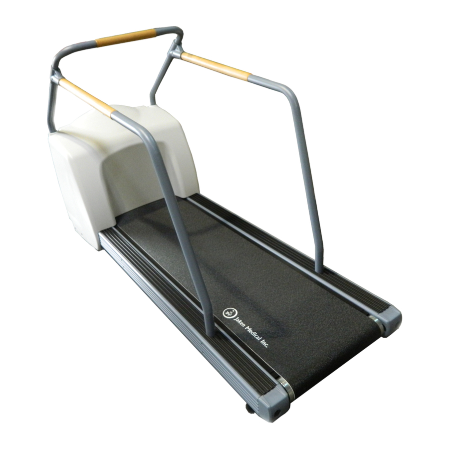
Page 23: Side View
Equipment Overview: General Description Side View Emergency Stop (ESTOP) Handrails Shroud Walking Belt Elevation Racks and Wheels Level Adjusting Feet Revision A GE T2100 Treadmill 2021403-031... -
Page 24: Rear View
Equipment Overview: General Description Rear View Standing Feet (For support when standing GE T2100 Treadmill upright on this end.) Connection Panel GE T2100 Treadmill Revision A 2021403-031... -
Page 25: Connection Panel
Equipment Overview: General Description Connection Panel The following illustration describes the connectors on the connection panel of the GE T2100 Treadmill, and identifies the general location of the serial number. RS 232 Serial Port RS 422 Serial Port Emergency Stop... - Page 26 Equipment Overview: General Description For your notes GE T2100 Treadmill Revision A 2021403-031...
-
Page 27: Installation
Installation Revision A GE T2100 Treadmill 2021403-031... - Page 28 For your notes GE T2100 Treadmill Revision A 2021403-031...
-
Page 29: Tools Required
This slight elevation provides for free wheel movement and prevents the shroud from scraping the floor. If you are moving the GE T2100 Treadmill after it has been in operation, use the controlling equipment to set the grade to approximately 7%. -
Page 30: Installation Checklist
Installation: Installation Checklist 3. When you have maneuvered the GE T2100 Treadmill into its new location, gently lower the end of the bed assembly to the floor. Installation Checklist The Installation Checklist is provided as a guide for the field engineer when installing a GE T2100 Treadmill. -
Page 31: Domestic Electrical Safety Tests
The voltage measurements should be: 200 to 240 nominal VAC between the two “hot” contacts. ❶ GROUND NOTE For proper and safe operation of the GE T2100 Treadmill, ensure the power source is clean. See “Power/Environmental Specifications” page A-4 for more details. Revision A... -
Page 32: Equipment Assembly
As recommended by the American Heart Association Exercise Standards (Special Report, Vol 82, No 6), the GE T2100 Treadmill should have front and side rails installed for patients to steady themselves. An emergency stop switch must be visible and readily accessible. - Page 33 7. Reassemble the shroud and align the grommets properly. Align the side rails to the predrilled guide holes in the front rails. Bolts T-bracket 2 Places Nuts 2 Places Typical two places Revision A GE T2100 Treadmill 2021403-031...
-
Page 34: Install Emergency Stop Switch
NOTE The emergency stop switch must be installed and the ESTOP cable plugged in to the GE T2100 Treadmill connection panel for the GE T2100 Treadmill to operate. If the ESTOP is not installed, the GE T2100 Treadmill will not operate. -
Page 35: Ground Continuity Test
COM 1, COM 2, COM C or COM D. The CASE RSS modem requires the use of either COM 1 or COM 2. Move the GE T2100 Treadmill interface cable to COM C or COM D only as necessary. -
Page 36: Secure The Cables
4-5. Check Emergency Stop Switch 1. Manually control the speed of the GE T2100 Treadmill from the controlling device. With the belt moving at a relatively high speed, press the emergency stop switch. The GE T2100 Treadmill belt will stop promptly but the belt will not lock, allowing for removal of foreign objects. - Page 37 1. Remove controlling device (CASE, MTC-1) cable or turn off the controlling device. 2. Unlock the emergency stop switch. 3. Connect the AC power cable on the GE T2100 Treadmill to the wall outlet. WARNING POWER CABLES – Route the AC Power cable away from moving parts.
-
Page 38: Check Ge T2100 Treadmill Level
0.0%. 2. Check the GE T2100 Treadmill level with a carpenter’s level. 3. If the GE T2100 Treadmill is uneven, adjust the feet at the rear of the GE T2100 Treadmill until it is level. 4. If you cannot level the GE T2100 Treadmill safely, move it to another location. -
Page 39: Leakage Test Diagrams
Total system leakage current must not exceed 300 microamperes. Table 1. Leakage Tests and Maximum Allowable Leakage Currents Test Applies To Maximum Current (µA) Ground-wire-leakage-to-ground GE T2100 Treadmill Gnd open = 1000 Chassis-leakage-to-ground GE T2100 Treadmill Gnd open = 500 Gnd closed = 100 Leakage Test Diagrams These diagrams show only a representation of how a typical leakage current tester functions. -
Page 40: Test #2
“To be tested” power connector on back of tester (may not be labeled on some testers). Tester Tester Polarity power Norm cord power Line Line cord Neutral Unit under Neutral test (UUT) Probe to Meter exposed chassis connectors 3-14 GE T2100 Treadmill Revision A 2021403-031... -
Page 41: Functional Checkout
Check the walking belt tightness. Get on the GE Adjust the belt tension. See “Walking Belt T2100 Treadmill and try to stop the belt at a slow Tension Adjustment” on page 4-5. speed with your feet, holding onto the handrail. - Page 42 Communicate with Host Can Host control elevation and speed? 1. Check that interface cable is properly connected. 2. Replace Interface cable. 3. Use the GE T2100 Treadmill Diagnostic Utility (TDU) to help troubleshoot the problem. See “GE T2100 Treadmill Diagnostic Utility (TDU)”...
-
Page 43: Double-Check Handles
Was leakage test performed by Biomed and did it “Equipment Assembly” on page 3-6. pass? Double-Check Handles Check to make sure all handles are secure. Verify that all screws on the handles are fastened securely. Revision A GE T2100 Treadmill 3-17 2021403-031... - Page 44 Installation: Functional Checkout For your notes 3-18 GE T2100 Treadmill Revision A 2021403-031...
-
Page 45: Maintenance
Maintenance Revision A GE T2100 Treadmill 2021403-031... - Page 46 For your notes GE T2100 Treadmill Revision A 2021403-031...
-
Page 47: Introduction
A regular equipment maintenance program helps prevent unnecessary equipment and power failures and also reduces possible health hazards. To help you establish a systematic maintenance routine, GE Medical Systems Information Technologies recommends that you periodically perform the maintenance and test procedures described in this manual, including: “Inspection and Cleaning”... -
Page 48: Inspection And Cleaning
Handrail and hardware Exterior Cleaning Turn the GE T2100 Treadmill system off. Clean the exterior surfaces with a clean, soft cloth and a mild dishwashing detergent diluted in water. Wring out the excess water from the cloth and take care not to drip solutions on the e-box connections and ports. -
Page 49: Walking Belt Tracking And Tension Adjustment
If the belt tracks to one side or the other, then you must adjust the belt tracking. It is not unusual for the GE T2100 Treadmill belt to move slightly off center while a person with a heavy gait is exercising. A properly adjusted belt re-centers itself when the person steps off the GE T2100 Treadmill. -
Page 50: Walking Belt Tracking Adjustment
3. If either adjustment in step 2 results in an over-adjustment of the belt tracking, loosen the pulley screw that was tightened and wait several minutes for the GE T2100 Treadmill belt position to stabilize. Then tighten the other pulley adjustment screw. -
Page 51: Theory Of Operation
Theory of Operation Revision A GE T2100 Treadmill 2021403-031... - Page 52 For your notes GE T2100 Treadmill Revision A 2021403-031...
-
Page 53: Ge T2100 Treadmill Block Diagram
Theory of Operation: GE T2100 Treadmill Block Diagram GE T2100 Treadmill Block Diagram Revision A GE T2100 Treadmill 2021403-031... -
Page 54: Power Board (Pcb) Theory
Initial Board Conditions The power board initial conditions are all at 0V. Power Input Requirements The GE T2100 Treadmill is used on single phase AC. The specific power ratings are 200-240VAC, 50-60 Hz, 16A. Power Distribution/Isolation The power board receives 200 to 240VAC power (nominal 220V). The isolation transformer supplies 12V to two switching regulators. -
Page 55: Power Supplies
These capacitors provide 3.3 Farads of capacitance that give the processor board power to logically power down activities in case of a loss of power to the GE T2100 Treadmill. Processor Board Connectors The power board has two connectors that directly interface with the processor board. -
Page 56: Elevation Sensor
The I/O connectors on the power board have current-limiting resistors, Zener diodes, or filtering capacitors wherever possible to prevent EMI from escaping the board. These components also limit rise-time and voltages which may come from ESD or other noise sources. GE T2100 Treadmill Revision A 2021403-031... -
Page 57: Power Board Input/Output Signal Requirements
See the illustration below for location of the J PINs. Table 1. J1 10-Pin Ribbon Between Power Board and Processor Board PIN # NAME TYPE IN/OUT FREQ COMMENT J1-1 +5.1V Digital Power Supply J1-2 DGND Digital Ground Supply Revision A GE T2100 Treadmill 2021403-031... - Page 58 IN/OUT FREQ. COMMENTS J6-1 220V_UP 50-60 Hz Power Up Elevation J6-2 J6-3 220V_DN 50-60 Hz Power Down Elevation J6-4 220V_UP 50-60 Hz Power Up Elevation J6-5 J6-6 220V_DN 50-60 Hz Power Down Elevation J6-7 GE T2100 Treadmill Revision A 2021403-031...
- Page 59 Low Limit Switch Table 6. J10, J11, J12 AC Power to Drive Controller PIN # NAME TYPE IN/OUT FREQ. COMMENTS J10-1 Ground J11-1 LINE 50-60 Hz Line Power Out J12-1 LINE 50-60 Hz Line Power Out Revision A GE T2100 Treadmill 2021403-031...
- Page 60 Line Power Out Table 8. J14 Power Cable to Processor Board PIN # NAME TYPE IN/OUT FREQ. COMMENTS J14-1 +5V ISO ISO Power Supply J14-2 ISOGND ISO Ground Supply J14-3 +VUNREG ISO Power Supply 5-10 GE T2100 Treadmill Revision A 2021403-031...
-
Page 61: Processor Board (Pcb) Theory
Theory of Operation: Processor Board (PCB) Theory Processor Board (PCB) Theory General Description The processor board and power board function together to control the GE T2100 Treadmill. The processor board contains the following: Micro-controller CPU circuitry (MC9S12DG128) " Flash Memory (calibration/history data) "... -
Page 62: Processor Circuitry
Its code is stored in the 128 KB Flash EPROM. The MC9s12DG128 addresses its memory internally. The processor handles all the I/O, including two serial channels, 4 analog inputs, and digital inputs and outputs to control the GE T2100 Treadmill grade, speed, calibration and ESTOP processes. Analog Inputs Ratiometric Inputs Elevation feedback (from the pot), +5.1V ISO ref, VUNREG ref are... -
Page 63: Esd And Emi Compatibility
250 VAC Operation The processor board’s main task is to monitor the proper GE T2100 Treadmill operation by testing selected variables from the system. In case of any variable operating out of specs, the firmware will first detect the event, then log it, and finally stop any further operation. -
Page 64: Self-Calibration
GE T2100 Treadmill starts to elevate (approximately 4 seconds). ESTOP In order to operate the GE T2100 Treadmill, the ESTOP plug must be attached to its receptacle on the processor board. Failure to perform this action will initiate a RESET* sequence on the microcontroller disabling any further power up sequence. -
Page 65: Processor Board Power Input Requirements
100 mA 100 mV 5.5 V +24V +24 VDC +/- 2% +/- 5% 600 mA 100 mV 25 V Processor Board Input/Output Signal Requirements See the illustration below for location of the J PINs. Revision A GE T2100 Treadmill 5-15 2021403-031... - Page 66 +24V Digital Gnd Supply J2-6 D_ESTOP* LOGIC PULSE Deceleration eStop Signal Table 12. J3 Host DB-9 COnnector PIN # NAME TYPE IN/OUT FREQ COMMENT J3-1 ISOGND ISO Gnd Supply J3-2 +5V ISO ISO Power Supply 5-16 GE T2100 Treadmill Revision A 2021403-031...
- Page 67 Drive RS422 Serial Comm J4-9 Table 14. J6 Isolated Power Input Connector PIN # NAME TYPE IN/OUT FREQ COMMENT J6-1 +5V ISO ISO Power Supply J6-2 ISOGND ISO Gnd Supply J6-3 +VUNREG ISO Power Supply Revision A GE T2100 Treadmill 5-17 2021403-031...
- Page 68 LIMIT* LOGIC PULSE Limit Switch Feedback J9-6 DGND Digital Gnd Supply J9-7 ELEV_FB Pot Elevation Feedback J9-8 DGND Digital Gnd Supply J9-9 UP/DOWN* LOGIC PULSE ELevation Direction Ctrl J9-10 +24V Digital Power Supply 5-18 GE T2100 Treadmill Revision A 2021403-031...
-
Page 69: Drive Controller Theory
The overall feedback loop is called the velocity loop or outer loop of the drive. While this system controls motor speed, it cannot control the exact motor speed since some error signal is Revision A GE T2100 Treadmill 5-19 2021403-031... - Page 70 Any speed error results in an output from the integrator that builds with time and causes an output to the current loop. This loop, therefore, will seek zero speed error. This is the type of velocity loop used in the GE T2100 Treadmill drive.
-
Page 71: Electrical Requirements
The orange wire from the side of the enclosure is connected to the sheetmetal enclosure and should be connected to the designated terminal on the power terminal block. Do not connect this wire to the GE T2100 Treadmill frame which would cause a safety hazard. - Page 72 Theory of Operation: Electrical Requirements For your notes 5-22 GE T2100 Treadmill Revision A 2021403-031...
-
Page 73: Troubleshooting
Troubleshooting Revision A GE T2100 Treadmill 2021403-031... - Page 74 For your notes GE T2100 Treadmill Revision A 2021403-031...
-
Page 75: Quickcheck Items
Treadmill will not operate. Power Switch When turning the GE T2100 Treadmill power switch off, there is a period of approximately 1 second when the remaining power cycles through the system. The GE T2100 Treadmill will not power up until all remaining power has cycled through the system. -
Page 76: Burn-In Mode
1. Remove controlling device (CASE, MTC-1) cable or turn off the controlling device. 2. Unlock the emergency stop switch. 3. Connect the AC power cable on the GE T2100 Treadmill to the wall outlet. WARNING POWER CABLES – Route the AC Power cable away from moving parts. - Page 77 Power Switch 4. Press and hold in the Calibration button. 5. Turn the power switch on the GE T2100 Treadmill to On. 6. Continue to hold the Calibration button until the GE T2100 Treadmill starts changing elevation (at least 4 seconds). This initiates the calibration routine.
- Page 78 The GE T2100 Treadmill elevates to 10°. d. The GE T2100 Treadmill elevates to 12.5°. e. The GE T2100 Treadmill activates the walking belt. The walking belt goes from 0 to 21.7 km/h (13.5 mph) in increments of .8 km/h (0.5 mph) every 7.5 seconds.
-
Page 79: Visual Inspection
Fraying or other damage Bent prongs or pins Cracked housing Loose screws in plugs Check that each terminal on the X1 connector is tightened securely. See “Drive Controller X1 PIN descriptions” on page 7-22 for torque requirements. Revision A GE T2100 Treadmill 2021403-031... - Page 80 PCBs Power Source Faulty wiring, especially AC outlet. See “AC Line Voltage Test” on page 3-5 Circuit not dedicated to system (Power source problems can cause static discharge, resetting problems, and noise) GE T2100 Treadmill Revision A 2021403-031...
-
Page 81: Ge T2100 Treadmill Diagnostic Utility (Tdu)
(Instead of the serial number, an optional 16-digit text can be entered.) Connect treadmill – A connection to the GE T2100 Treadmill will be established. This must be done before you can download a log file. The GE T2100 Treadmill characteristics (Type, Version, ...) are shown in the status line when the connection is done. - Page 82 Erase treadmill events – The GE T2100 Treadmill events will be erased in the device flash. All previous events stored are lost. The power up time, belt time, and elevation time are reset.
-
Page 83: Tdu Application Error Definitions
GE T2100 Treadmill, the scratch file 'TDU Dwnld.txt' could not be opened. If the TDU was viewing an event log or done retrieving from the GE T2100 Treadmill the log, the log file could not be opened. Verify the file exists in the default TDU directory. -
Page 84: Download The Tdu
For laptop/PC – Connect an RS232 DB9 cable (pn 700609-001) to " the serial port on the FE laptop and the DB9 connector on the GE T2100 Treadmill, and launch TDU. For CASE – Make sure the CASE is connected to the GE T2100 "... -
Page 85: Tdu Error Log Date And Time Information
January 1, 2050, 0:00:00 and is then stored into the flash memory. When power is applied to the GE T2100 Treadmill, the SDT is set to the saved SDT in the flash memory. While power is applied, the system updates the SDT every second. - Page 86 Troubleshooting: GE T2100 Treadmill Diagnostic Utility (TDU) Host Synchronized Mode When the GE T2100 Treadmill receives a valid date and time from a host device, such as CASE v6 or the TDU, the GE T2100 Treadmill will enter the Host Synchronized Mode. The GE T2100 Treadmill will stay in this mode until power is lost to the GE T2100 Treadmill.
-
Page 87: Tdu Troubleshooting Tables And Status Leds
If self-calibration has been performed, the LEDs will all turn off and then behave as described in the table below. When power is removed from the e-box, all LEDs will turn on until the system has completed the shutdown routines. Status LEDs Revision A GE T2100 Treadmill 6-15 2021403-031... - Page 88 1. Verify the ESTOP switch is correctly installed 2. Check the fuses 3. Check the power test points for +24v and +5v If all the items above are working correctly, the problem is not in the e-box. 6-16 GE T2100 Treadmill Revision A 2021403-031...
-
Page 89: Tdu Troubleshooting Table
0x02 Fatal Belt Error Measures the drive motor RPM. (Halts 1. Powercycle the GE T2100 Treadmill and monitor the GE T2100 Current Treadmill for reoccurrence of this error. (This may be an isolated Operation) incident.) 2. Check for loose wiring and connections between the drive controller and the drive motor. - Page 90 The ambient temperature inside the e-box has reached 65° C (Halts <XX> (149° F). Current 1. Remove power from the GE T2100 Treadmill and allow to cool Operation) (where XX equals the off. temperature in Celsius) 2. Power up the GE T2100 Treadmill and monitor the GE T2100 Treadmill for reoccurrence of this error.
- Page 91 <01> Could not check for drive controller, or the processor board and the host. Current errors. 1. Powercycle the GE T2100 Treadmill and monitor the GE T2100 Operation) <02> Could not check for drive Treadmill for reoccurrence of this error. (This may be an isolated axis errors.
- Page 92 Celsius) rise to near-fatal levels. (65° C is fatal.) 1. Remove power from the GE T2100 Treadmill and allow to cool off. 2. Power up the GE T2100 Treadmill and monitor the GE T2100 Treadmill for reoccurrence of this error.
-
Page 93: Drive Controller Status Led
Flashing Firmware download in progress. Green Solid Red Drive is disabled, but no errors are latched. Alternating Undervoltage warning (no AC power to the X1 connector), but no errors Red/Green are latched. Flashing Revision A GE T2100 Treadmill 6-21 2021403-031... - Page 94 If an undervoltage trip occurs in conjunction with another error, the drive will flash the code of the additional error. See the troubleshooting table below for the event / error code and it’s corresponding red flashing LED. 6-22 GE T2100 Treadmill Revision A 2021403-031...
-
Page 95: Tdu Troubleshooting Table For Drive Controller
0x10 DC bus over-voltage trip Indicates the DC Bus voltage has exceeded the overvoltage level. 1. Powercycle the GE T2100 Treadmill and monitor the GE T2100 Treadmill for reoccurrence of this error. (This may be an isolated incident.) 2. Verify that the AC power supply voltage is correct. See “AC Line... - Page 96 Indicates loss of encoder/resolver feedback and may indicate that the feedback cable has become detached, one of the signals has broken, or noise is present. 1. Powercycle the GE T2100 Treadmill and monitor the GE T2100 Treadmill for reoccurrence of this error. (This may be an isolated incident.) 2.
- Page 97 1. Powercycle the GE T2100 Treadmill and monitor the GE T2100 Treadmill for reoccurrence of this error. (This may be an isolated incident.) 2.
- Page 98 Other errors, including: Internal supply error. Encoder supply error. Parameter restore failure. Power base not recognized. Under voltage trip. 1. Powercycle the GE T2100 Treadmill and monitor the GE T2100 Treadmill for reoccurrence of this error. (This may be an isolated incident.) 2.
-
Page 99: Power Supply Voltage Checks And Fuses
+/- 5% DGND TP4 +24V +24 VDC +/- 5% GND_24V TP3 Also verify that U15, pin 8, has 8.2 VDC (+/- 5%) Processor Board Voltage Check Test Points TP2, TP3, TP4 TP5, TP6, TP7 Revision A GE T2100 Treadmill 6-27 2021403-031... -
Page 100: Power Board Voltage Checks
Nominal value Test range Test point Reference ISO Power +5V_ISO 5.1V +/- 5% ISOGND TP4 Non-Isolated DGND 5.1V +/- 5% DGND TP2 Power Power Board Voltage Check Test Points TP1, TP2 TP4, TP5 6-28 GE T2100 Treadmill Revision A 2021403-031... -
Page 101: Power Board Fuse Locations
The 20A and 2.5A fuses are located on the power board. Remove the cover of the e-box to access and change these fuses. The 1/2A fuses are accessed at the connector panel on the back of the GE T2100 Treadmill. 2.5 A Fuses (2) - Page 102 Troubleshooting: Power Supply Voltage Checks and Fuses For your notes 6-30 GE T2100 Treadmill Revision A 2021403-031...
-
Page 103: Assembly/Disassembly
Assembly/Disassembly Revision A GE T2100 Treadmill 2021403-031... - Page 104 For your notes GE T2100 Treadmill Revision A 2021403-031...
-
Page 105: Assembly And Disassembly Procedures
Assembly/Disassembly: Assembly and Disassembly Procedures Assembly and Disassembly Procedures Required Tools and Supplies To maintain and repair the GE T2100 Treadmill, you will need the following: Standard hand tools, including: Socket and Driver set – 9mm (3/8”) or 12mm (1/2”) drive, "... -
Page 106: Location Of Major Sub-Assemblies
(“floating”) ground when power is applied. Unplug the unit from the power source before proceeding. Drive Controller Electronics Box (e-box) Connector Panel Flywheel Elevation Pot (under Electronics Box) Elevation Motor and Worm Gear Elevation Limit Switch GE T2100 Treadmill Revision A 2021403-031... - Page 107 Assembly/Disassembly: Assembly and Disassembly Procedures Drive Motor Walking Belt Drive Electronics Box Belt (e-box) Front Roller Rear Roller Revision A GE T2100 Treadmill 2021403-031...
-
Page 108: Front Roller Replacement
Motor Replacement” on page 7-12 for steps relative to loosening the drive belt. 3. Loosen the walking belt tension bolts on the end of the GE T2100 Treadmill. Tension Bolts 4. On the drive-belt side of the GE T2100 Treadmill, remove the 3 bolts fastening the walking belt drive gear to the roller. - Page 109 “Adjust Drive Belt Tracking” on page 7-17. 10. Adjust walking belt tracking and tension. See “Walking Belt Tension Adjustment” on page 4-5. 11. Calibrate the GE T2100 Treadmill. See “Self-Calibration” on page 3- 10.” Revision A GE T2100 Treadmill 2021403-031...
-
Page 110: Rear Roller Replacement
Rear Roller Replacement 1. Turn the power switch off and disconnect the power cord from the wall outlet. 2. Remove the walking belt tension bolts on the end of the GE T2100 Treadmill and remove the end caps. Tension Bolts 3. -
Page 111: Walking Belt And Board Replacement
3. Remove the tension bolt and the right end cap. 4. Loosen the keeper nut on the right foot, and unscrew and remove the right foot. Loosen Left Tension Bolt Remove Right Tension Bolt and End Cap Remove Right Foot Revision A GE T2100 Treadmill 2021403-031... - Page 112 Assembly/Disassembly: Walking Belt and Board Replacement 5. On the front right side of the GE T2100 Treadmill, remove the eight, 1/2-inch bolts that hold the frame’s sliding bracket in place. Sliding Bracket Bolts, 8 Places Sliding Bracket 6. Slide the bracket left, into the frame.
- Page 113 Assembly/Disassembly: Walking Belt and Board Replacement 4. Place the new walking board on the GE T2100 Treadmill with the beveled edges facing down, towards the rollers. 5. Secure the new walking board to the bed assembly with the 8 Allen- head screws.
-
Page 114: Drive Motor Replacement
4. Unscrew the wires from the X1 connector that lead to the motor. See “Drive Controller X1 PIN descriptions” on page 7-22. 5. Cut any plastic retaining straps. Motor Power Motor Control Cable Cable 6. Loosen the 4 motor mounting bolts, but DO NOT remove them. 7-12 GE T2100 Treadmill Revision A 2021403-031... - Page 115 7. Lower the motor using the 2 drive belt tension adjustment bolts until the drive belt can be removed from the sprocket. Drive Belt Tension Adjustment Bolts 2 Upper Motor Mounting Bolts Sprocket Drive Belt 2 Lower Motor Mounting Bolts (underneath the motor) Revision A GE T2100 Treadmill 7-13 2021403-031...
- Page 116 14. Remove the 4 motor mounting bolts and carefully remove the motor. NOTE The drive motor weighs 33 lbs. (15 k) 15. Swap motors and re-assemble in reverse order following the note below when installing the hub and flywheel. 7-14 GE T2100 Treadmill Revision A 2021403-031...
- Page 117 16. When the new drive motor is installed, adjust the drive belt tension and tracking. See “Drive Belt Adjustments” on page 7-16 and “Adjust Drive Belt Tracking” on page 7-17. 17. Calibrate the GE T2100 Treadmill. See “Self-Calibration” on page 3- 10.” Revision A GE T2100 Treadmill 7-15...
-
Page 118: Drive Belt Replacement And Adjustments
Tighten these 1/2-inch bolts to adjust the drive belt tension (clockwise to tighten). Drive Belt Adjustment Bolts 2 Places 2 Upper Motor Mounting Bolts 2 Lower Motor Mounting Bolts (underneath the motor) 7-16 GE T2100 Treadmill Revision A 2021403-031... - Page 119 If the drive belt tracks off center on the lower sprocket, adjust the position of the top sprocket until the drive belt tracks in the center of the lower sprocket. When the drive belt is tracking Revision A GE T2100 Treadmill 7-17 2021403-031...
- Page 120 Assembly/Disassembly: Drive Belt Replacement and Adjustments correctly, calibrate the GE T2100 Treadmill. See “Self-Calibration” page 3-10.” 7-18 GE T2100 Treadmill Revision A 2021403-031...
-
Page 121: Elevation Motor Replacement
7-25. 5. Disconnect the elevation motor power cable plug and jumpers at the electronics box and remove all tie wraps on the cable. 6. Place the GE T2100 Treadmill on its side so the elevation motor is on top. WARNING The elevation motor wormgear supports the elevation shaft when the motor is in place. - Page 122 See “Potentiometer Installation Procedure:” on page 7-23 for procedures when installing the potentiometer. 11. Replace the tie wraps for the elevation motor wiring harness. 12. Calibrate the GE T2100 Treadmill. See “Self-Calibration” on page 3- 10.” 7-20 GE T2100 Treadmill...
-
Page 123: Drive Controller Replacement
3. Disconnect all connectors from the drive controller. 4. Remove the 4 nuts from the drive controller mounting bracket and remove the mounting bracket and drive controller from the GE T2100 Treadmill. 5. Remove the 4 nuts from the drive controller fastening points. -
Page 124: Drive Controller X1 Pin Descriptions
Orange-Yellow wire earth/ground going to the motor. Can be inverted with the other Gnd. Orange wire earth/ground going to the ground terminal on the power board. Can be inverted with the other Gnd. 7-22 GE T2100 Treadmill Revision A 2021403-031... -
Page 125: Elevation Potentiometer Replacement
Assembly/Disassembly: Elevation Potentiometer Replacement Elevation Potentiometer Replacement General Replace the Elevation Potentiometer Harness on GE T2100 Treadmills experiencing elevation hesitation and seeking problems or a faulty GE T2100 Treadmill stop condition during an elevation change. Elevation Potentiometer Harness Assembly Replacement 1. - Page 126 This must be done in order to maintain the 1–2 turns established in Step 4. Also be sure that the cables are toward the rear of the GE T2100 Treadmill. Attach the tube far enough on to the elevation shaft such that the mounting plate is within 1/16th inch or less of the threaded stand-offs.
- Page 127 Manually increase the elevation to a 25% grade and confirm that 25.0 is displayed. 10. Re-assemble the remaining components to complete the overall GE T2100 Treadmill assembly. Potentiometer Removal Guidelines NOTE If it is necessary to remove the potentiometer with the intention of re-installation, please follow these guidelines to reduce the risk of damage to the potentiometer.
- Page 128 If this does occur, the entire potentiometer harness will require replacement.The potentiometer is susceptible to damage if axial pulling forces are applied to the shaft. Do not attempt to remove the potentiometer by grabbing the potentiometer and pulling it off. 7-26 GE T2100 Treadmill Revision A 2021403-031...
- Page 129 3. Gently push the tube to the left to remove it from the elevation shaft. NOTE If needle-nose pliers are not available, a standard slotted screwdriver can be used to work the coupling tube off the elevation shaft. Revision A GE T2100 Treadmill 7-27 2021403-031...
-
Page 130: Pcbs And Power Supply Replacement
Ribbon Cable from Power PCB to Processor PCB Power Supply Power PCB to 24V Power Supply Harness Power PCB Power-In Filter to Power Harness PCB Harness 275A EMI Filter Switch to Filter Harness 7-28 GE T2100 Treadmill Revision A 2021403-031... - Page 131 5. Fasten the new PCB/power supply to the e-box using the mounting screws. 6. Reconnect any wiring harnesses/connections. 7. Replace the e-box cover and the shroud. 8. Calibrate the GE T2100 Treadmill. See “Self-Calibration” on page 3- 10.” Revision A...
- Page 132 Assembly/Disassembly: PCBs and Power Supply Replacement For your notes 7-30 GE T2100 Treadmill Revision A 2021403-031...
-
Page 133: Ordering Parts
Ordering Parts Revision A GE T2100 Treadmill 2021403-031... - Page 134 For your notes GE T2100 Treadmill Revision A 2021403-031...
-
Page 135: Field Replaceable Units
Braking Resistor & Harness 2023446-001 Communication Harness Processor to Drive Controller 2023442-001 24Volt Distribution Harness 2026180-001 Shroud w/ T2100 label (front) 2026390-001 Shroud Cover w/ service label (rear) 2022341-001 Power PCB (located in the e-box) 2021939-001 Processor PCB/Service & Host I/F PCB (located in the e-box) - Page 136 2023406-002 FUSE 13/32 FLM 20 Amp SLOW F4, F6 420824-001 FUSE SB, 2.5 Amp, 250Volt F1, F2 700609-001 RS 232 Interface Cable (for CASE to GE T2100 Treadmill, and GE T2100 Treadmill to TDU on laptop) 408890-001 Elevation Motor 408895-001...
- Page 137 Appendix A – Technical Specifications Revision A GE T2100 Treadmill 2021403-031...
- Page 138 For your notes GE T2100 Treadmill Revision A 2021403-031...
-
Page 139: Appendix A - Technical Specifications
73.7 cm x 195.6 cm (29 in x 77 in) Walking Surface Height 14.0 cm (5.5 in) Handrail Height Above Walking Surface Front: 101.6 cm (40 in) Side: Maximum 88.9 cm (35 in) descending at 5° angle to 81.3 cm (32 in) Revision A GE T2100 Treadmill 2021403-031... - Page 140 Handling of Disposable Supplies and Use only parts and accessories manufactured or recommended by Other Consumables GE Medical System Information Technologies. Follow manufacturer’s instructions for use for disposable/consumable product. Follow local environmental guidelines concerning the disposal of hazardous materials (e.g. lead acid batteries).
-
Page 141: Ul Classification
500 hPa to 1060 hPa (375 mmHg to 795 mmHg) UL Classification Medical Equipment With Respect to Electric Shock, Fire, and Mechanical Hazards Only, In Accordance with UL 60601-1, CAN/CSA C22.2 No.601.1, and IEC 60601-1 XXXX Revision A GE T2100 Treadmill 2021403-031... - Page 142 Appendix A – Technical Specifications: Technical Specifications GE T2100 Treadmill Revision A 2021403-031...
-
Page 143: Appendix B - Electromagnetic Compatibility (Emc
Appendix B – Electromagnetic Compatibility (EMC) Revision A GE T2100 Treadmill 2021403-031... - Page 144 For your notes GE T2100 Treadmill Revision A 2021403-031...
- Page 145 Appendix B – Electromagnetic Compatibility (EMC): Electromagnetic Compatibility (EMC) Electromagnetic Compatibility (EMC) Changes or modifications to this system not expressly approved by GE Medical Systems can cause EMC issues with this or other equipment. This system is designed and tested to comply with applicable regulation regarding EMC and must be installed and put into service according to the EMC information stated in this appendix.
-
Page 146: Electromagnetic Emissions
Guidance and manufacturer’s declaration – electromagnetic emissions The GE T2100 Treadmill is intended for use in the electromagnetic environment specified below. The customer or user of the GE T2100 Treadmill should assure that it is used in such an environment. -
Page 147: Electromagnetic Immunity
Guidance and manufacturer’s declaration – electromagnetic immunity The GE T2100 Treadmill is intended for use in the electromagnetic environment specified below. The customer or user of the GE T2100 Treadmill should assure that it is used in such an environment. - Page 148 Guidance and manufacturer’s declaration – electromagnetic immunity The GE T2100 Treadmill is intended for use in the electromagnetic environment specified below. The customer or user of the GE T2100 Treadmill should assure that it is used in such an environment.
-
Page 149: Separation Distance
Portable and mobile RF communications equipment and the GE T2100 Treadmill The GE T2100 Treadmill is intended for use in the electromagnetic environment on which radiated RF disturbances are controlled. The customer or the user of the GE T2100 Treadmill can help prevent electromagnetic interference by maintaining a minimum distance between portable and mobile RF communications equipment (transmitters) and the GE T2100 Treadmill as recommended below, according to the maximum output power of the communications equipment. -
Page 150: Exceptions
Guidance Electrostatic Do not expose the connection panel at the rear of the discharge (ESD) Direct discharge I/O connectors compliance level to 4kV only GE T2100 Treadmill to any source of ESD while in operation. Electrical fast transient/burst No Exceptions... -
Page 151: Compliant Cables And Accessories
The table below lists cables, transducers, and other applicable accessories with which GE Medical Systems claims EMC compliance. NOTE: Any supplied accessories that do not affect EMC compliance are not included. Maximum Cable / Cord... - Page 152 Appendix B – Electromagnetic Compatibility (EMC): Compliant Cables and Accessories For your notes B-10 GE T2100 Treadmill Revision A 2021403-031...