
Related Manuals for GE Discovery LS


Summary of Contents for GE Discovery LS
- Page 1 GE Healthcare Discovery LS System Service Manual OPERATING DOCUMENTATION 2307224-100 Rev 6...
- Page 2 GE H EALTHCARE 2307224-100, R LS S IRECTION EVISION ISCOVERY YSTEM ERVICE ANUAL Page 2...
- Page 3 HEALTHCARE 2307224-100, R LS S IRECTION EVISION ISCOVERY YSTEM ERVICE ANUAL IMPORTANT PRECAUTIONS LANGUAGE WARNING • This Service Manual is available in English only. • If a customer's service provider requires a language other than English, it (EN) is the customer's responsibility to provide translation services. •...
- Page 4 Serviceanleitung gelesen und verstanden zu haben. • Wird diese Warnung nicht beachtet, so kann es zu Verletzungen des Kundendiensttechnikers, des Bedieners oder des Patienten durch stromschläge, Mechanische oder Sonstige gefahren kommen. ΠΡΟΕΙΔΟΠΟΙΗΣΗ • Το παρόν εγχειρίδιο σέρβις διατίθεται στα αγγλικά μόνο.
- Page 5 HEALTHCARE 2307224-100, R LS S IRECTION EVISION ISCOVERY YSTEM ERVICE ANUAL AÐVÖRUN • Þessi þjónustuhandbók er eingöngu fáanleg á ensku. • Ef að þjónustuveitandi viðskiptamanns þarfnast annas tungumáls en (IS) ensku, er það skylda viðskiptamanns að skaffa tungumálaþjónustu. • Reynið ekki að afgreiða tækið nema að þessi þjónustuhandbók hefur verið...
- Page 6 GE H EALTHCARE 2307224-100, R LS S IRECTION EVISION ISCOVERY YSTEM ERVICE ANUAL ADVARSEL • Denne servicehåndboken finnes bare på engelsk. • Hvis kundens serviceleverandør trenger et annet språk, er det kundens (NO) ansvar å sørge for oversettelse. • Ikke forsøk å reparere utstyret uten at denne servicehåndboken er lest og forstått.
- Page 7 HEALTHCARE 2307224-100, R LS S IRECTION EVISION ISCOVERY YSTEM ERVICE ANUAL UPOZORNENIE • Tento návod na obsluhu je k dispozícii len v angličtine. • Ak zákazníkov poskytovateľ služieb vyžaduje iný jazyk ako angličtinu, (SK) poskytnutie prekladateľských služieb je zodpovednos″ou zákazníka. •...
- Page 8 In performing all electrical work on these products, GE will use its own specially trained field engineers. All of GE’s electrical work on these products will comply with the requirements of the applicable electrical codes.
- Page 9 GE Healthcare Radiation Safety Officer to use radioactive materials to service this equipment. GE Healthcare Services is required to notify the applicable U.S. state agency PRIOR to any source service event involving pin source handling. See NUC/PET Radioactive material guides for specific instruction or contact your EHS Specialist.
- Page 10 GE H EALTHCARE 2307224-100, R LS S IRECTION EVISION ISCOVERY YSTEM ERVICE ANUAL Page 10 Important Precautions...
- Page 11 HEALTHCARE 2307224-100, R LS S IRECTION EVISION ISCOVERY YSTEM ERVICE ANUAL Revision History Revision Date Reason for Change 10/14/01 First release 2/02 CH 2: Safety update; CH 5: Software install corrections and update; CH 10: Planned Maintenance update; CH 11: Wiring Connections update; App A: System Calibration Quick Guide added Updated Software Load from Cold (LFC) 11/19/02...
- Page 12 GE H EALTHCARE 2307224-100, R LS S IRECTION EVISION ISCOVERY YSTEM ERVICE ANUAL Revision Date Reason for Change 03/07/07 Changed "eNTEGRA" to "Xeleris". CH 1: - Updated the manual references in Sections 1.3 on page - Added new Sections: 1.4 on page 34, Required Skill Set and Tools and 1.5 on page...
-
Page 13: Table Of Contents
General Installation Safety Measures................42 Section 1.7 Regulatory Information..................42 1.7.1 Standard Compliance ...................... 42 Chapter 2 Discovery LS System Safety Information ............43 Section 2.1 CT System Safety ..................... 43 Section 2.2 Normal CT System Operational Safety............43 2.2.1 Potential Hazards ...................... - Page 14 GE H EALTHCARE 2307224-100, R LS S IRECTION EVISION ISCOVERY YSTEM ERVICE ANUAL 2.2.2 Safety Awareness Indicators................... 44 2.2.2.1 Labels ......................44 2.2.2.2 Lights and Lamps .................... 44 2.2.3 Emergency Switches, Buttons and Locks ............... 45 2.2.3.1 System Emergency Off (E-Off) Switch ............45 2.2.3.2...
- Page 15 GE H EALTHCARE 2307224-100, R LS S IRECTION EVISION ISCOVERY YSTEM ERVICE ANUAL 2.7.1.3 Circuit Breakers and Switches - CPDU............63 2.7.1.4 Mechanical Hazards - None................64 2.7.2 New Global Power Distribution Unit (NGPDU) ..............64 2.7.2.1 Hazard Awareness Indicators - NGPDU ............65 2.7.2.2...
- Page 16 GE H EALTHCARE 2307224-100, R LS S IRECTION EVISION ISCOVERY YSTEM ERVICE ANUAL 3.3.1.3 PDU ......................... 81 3.3.2 Gantry ..........................81 3.3.3 Detector Ring ........................82 3.3.4 PCU..........................82 3.3.5 Power Switch Box ......................82 3.3.6 Gantry Motion Control Board Rack ................. 82 Section 3.4...
- Page 17 GE H EALTHCARE 2307224-100, R LS S IRECTION EVISION ISCOVERY YSTEM ERVICE ANUAL Chapter 5 Console ........................ 107 Section 5.1 CT-PET Console Functional Description ............. 107 Section 5.2 Console Connections ..................109 Chapter 6 Table ........................111 Section 6.1 CT-PET Table Functional Description ............111 6.1.1...
- Page 18 GE H EALTHCARE 2307224-100, R LS S IRECTION EVISION ISCOVERY YSTEM ERVICE ANUAL 6.2.6.11 Install the Table Bulkhead (If Necessary) ............143 6.2.6.12 Install the Base Axis Motor I Cable (P/N 2323724) ........144 6.2.6.13 Install the Clutch Control I Cable (P/N 2340390)........... 145 6.2.6.14 Install Clutch Driver Unit (P/N 2340282)............
- Page 19 GE H EALTHCARE 2307224-100, R LS S IRECTION EVISION ISCOVERY YSTEM ERVICE ANUAL 6.2.10 Manual Table Wiring...................... 213 Section 6.3 Troubleshooting Tips..................215 6.3.1 Potentiometer Counts Differ ..................215 6.3.1.1 Symptom ......................215 6.3.1.2 Probable Causes and Suggestions..............215 6.3.2 CT-PET Position Latch Solenoid Fails to Engage ............
- Page 20 GE H EALTHCARE 2307224-100, R LS S IRECTION EVISION ISCOVERY YSTEM ERVICE ANUAL Section 7.2 CT Gantry Field Replaceable Units (FRUs) ..........226 Section 7.3 CT Gantry Replacement Procedures ............226 Section 7.4 PET Gantry Field Replaceable Units (FRUs) ..........226 Section 7.5...
- Page 21 Power and Data Cables Checklist..............263 10.1.1 CT Electronics Cabinet ....................263 10.1.2 PET Electronics Cabinet....................264 10.1.3 Discovery LS Console ....................265 10.1.4 Table Retractor Cables....................266 10.1.4.1 Manual Table Retractor Cables ..............266 10.1.4.2 Automated and Extended Table Retractor Cables......... 267 10.1.5 Secondary Base Cables ....................
- Page 22 GE H EALTHCARE 2307224-100, R LS S IRECTION EVISION ISCOVERY YSTEM ERVICE ANUAL 11.2.4 Secondary Base Cables....................302 Section 11.3 Covers......................303 11.3.1 Cover Sections and Components ................. 304 Section 11.4 Brackets for the Covers - Required Parts ............ 309 11.4.1 Brackets ........................
- Page 23 GE H EALTHCARE 2307224-100, R LS S IRECTION EVISION ISCOVERY YSTEM ERVICE ANUAL Section A.1 System Drawings ................... 339 Section A.2 Part Lists ......................342 A.2.1 Gantry and Cables......................342 A.2.2 Base Casting ......................... 342 A.2.3 Legs ..........................343 A.2.4 Linear Bearings......................
- Page 24 GE H EALTHCARE 2307224-100, R LS S IRECTION EVISION ISCOVERY YSTEM ERVICE ANUAL Page 24 Table of Contents...
- Page 25 Gantry Rotation Lock Out ........................38 Discovery LS System Safety Information ......43 Figure 2-1: Laser Light Warning and Regulatory Compliance Labels ..............44...
- Page 26 GE H EALTHCARE 2307224-100, R LS S IRECTION EVISION ISCOVERY YSTEM ERVICE ANUAL Figure 3-11: Grounding Diagram ........................... 92 Figure 3-12: PDU Circuit Breaker Switches ......................94 Figure 3-13: Image Monitor Screen Showing PET and Exam Rx Icons on Desktop Selection Area ..... 95 Figure 3-14: Desktop Selection Area Showing Shut-Down Button ................
- Page 27 GE H EALTHCARE 2307224-100, R LS S IRECTION EVISION ISCOVERY YSTEM ERVICE ANUAL Figure 6-28: Determine the Right Secondary Base Rail Revision ................133 Figure 6-29: CT Drill Template Hole Labels (Viewed from the Rail Exterior) ............134 Figure 6-30: Finish Tapping the "A" Holes ......................134 Figure 6-31: Fasten CT Drill Template to Right Rail Exterior ................135...
- Page 28 GE H EALTHCARE 2307224-100, R LS S IRECTION EVISION ISCOVERY YSTEM ERVICE ANUAL Figure 6-84: CT Plug ............................170 Figure 6-85: CT Detent/Flag Assembly ........................ 171 Figure 6-86: PET Detent/Flag Assembly ......................172 Figure 6-87: Adjust PET Detent for Recorded Distance Between Scan Planes ..........173 Figure 6-88: PET Detent Adjuster, P/N 2332092 ....................
- Page 29 GE H EALTHCARE 2307224-100, R LS S IRECTION EVISION ISCOVERY YSTEM ERVICE ANUAL Figure 6-140: Hardware Configuration Panel ......................211 Figure 6-141: Final PET and CT Flag Adjustment ....................212 Figure 6-142: Adjust PET Flag ..........................213 Figure 6-143: 2328900-2SCH ..........................213 Figure 6-144: 2338513SCH ............................214...
- Page 30 Electrical Connections ..........263 Figure 10-1: Discovery LS Grounding Connections (Manual and Automated Tables) ........274 Figure 10-2: CT System with H2 Interconnect Diagram (Manual Tables) ............
- Page 31 Figure A-3: Discovery LS Linear Bearing Assembly and Adjuster Assembly .............340 System Calibration Quick Guide ........347...
-
Page 32: Direction 2307224-100, Revision Discovery Ls System Service Manual
GE H EALTHCARE 2307224-100, R LS S IRECTION EVISION ISCOVERY YSTEM ERVICE ANUAL Page 32 List of Figures... -
Page 33: Preface
ANUAL Chapter 1 - Preface Scope of this Manual The manual provides installation and service information for the Discovery LS PET-CT imaging system and contains the following chapters: • Chapter 1 - Preface • Chapter 2 - System Safety Information •... -
Page 34: Required Skill Set And Tools
All mechanical installers must meet these minimum requirements. Only people trained and experienced in the service process of a GE PET Discovery scanner should perform the work described in this document. All training records will be kept and verified in My Learning. -
Page 35: Tools Required
ERVICE ANUAL 1.4.2 Tools Required Table 1-1 lists the tools recommended for the DLS installation, but not supplied by GE. Table 1-1: : Recommended Installation Tools Description Quantity Standard Field Engineer’s Tool Kit May need the additional tools listed below:... -
Page 36: System Lock-Out And Tag-Out (Loto)
GE H EALTHCARE 2307224-100, R LS S IRECTION EVISION ISCOVERY YSTEM ERVICE ANUAL System Lock-Out and Tag-Out (LOTO) Please follow the current LOTO procedures at the installation site. The instructions that follow are general. This manual assumes anyone working on the system is trained to safely LOTO the system at the A1 panel, according to the current standards and criteria. -
Page 37: Electrical Energy
HEALTHCARE 2307224-100, R LS S IRECTION EVISION ISCOVERY YSTEM ERVICE ANUAL 1.5.2 Electrical Energy 1.5.2.1 Removing Power from the System 1.) To prepare for shutdown of the equipment, notify affected personnel working in the area, via verbal communication, that LOTO is being performed. 2.) Bring the system software down at the Operator console. -
Page 38: Gantry Rotation (Mechanical And Gravitational Energy)
GE H EALTHCARE 2307224-100, R LS S IRECTION EVISION ISCOVERY YSTEM ERVICE ANUAL 1.5.3 Gantry Rotation (Mechanical and Gravitational Energy) 1.5.3.1 Disable Gantry Rotation 1.) Remove the right side gantry cover and place in a safe location. 2.) Disable the Axial Drive from the STC Backplane. -
Page 39: General Safety Guidelines
7.) The service engineer must be well acquainted with the Safety chapter of the Discovery LS Operator Guide, P.N. 2288677-100. 8.) Safe servicing requires that the field engineer has a thorough knowledge of all equipment controls and safety devices. -
Page 40: Iec Symbols
GE H EALTHCARE 2307224-100, R LS S IRECTION EVISION ISCOVERY YSTEM ERVICE ANUAL WARNING WARNINGS ARE USED TO IDENTIFY CONDITIONS OR ACTIONS FOR WHICH A SPECIFIC HAZARD IS KNOWN TO EXIST, WHICH MAY CAUSE SEVERE PERSONAL INJURY, DEATH OR SUBSTANTIAL PROPERTY DAMAGE IF THE INSTRUCTIONS ARE IGNORED. -
Page 41: General Hazards
HEALTHCARE 2307224-100, R LS S IRECTION EVISION ISCOVERY YSTEM ERVICE ANUAL 1.6.3 General Hazards Some repair/replacement procedures require the removal of protective covers, exposing parts at high temperatures or with pinch points. Read the safety/warning labels and follow the instructions in this System Service Manual to prevent burns or injuries. -
Page 42: General Installation Safety Measures
The manufacturer takes no responsibility for any interference caused by the use of non- recommended interconnect cables or by unauthorized change or modifications to the Discovery LS equipment. Unauthorized changes or modifications may void the users’ authority to operate the equipment. -
Page 43: Discovery Ls System Safety Information
If any of the covers should become damaged, contact your local GE Sales or Service representative immediately for replacement or repair. Only qualified service personnel trained in the service and operation of this scanner should remove any cover or service this equipment. -
Page 44: Safety Awareness Indicators
ISCOVERY YSTEM ERVICE ANUAL 2.2.2 Safety Awareness Indicators Numerous indicators are employed in the Discovery LS system to promote safety awareness. 2.2.2.1 Labels Figure 2-1: Laser Light Warning and Regulatory Compliance Labels Figure 2-2: X-ray Icon 2.2.2.2 Lights and Lamps Gantry and Console X-Ray On Indicator Lamps Both the gantry and the console have x-ray indicator displays. -
Page 45: Emergency Switches, Buttons And Locks
If a room warning light was installed and connected to the CT system correctly, the room warning light will illuminate whenever X-rays are present, by default. The room warning light can also be configured to illuminate whenever high voltage is present. See the Discovery LS System Installation Manual, Direction 2317946-100 for wiring and configuration details. 2.2.3... -
Page 46: System Emergency Stop (E-Stop) Switches
Figure 2-6, or at the console, shown in Figure 2-7. E-Stop Button Reset and Lamp Figure 2-6: Gantry E-Stop Reset Button Console (SCIM) E-Stop Button Figure 2-7: Console E-Stop Button Page 46 Chapter 2 - Discovery LS System Safety Information... -
Page 47: Figure 2-8: Table Tape Switches
Sudden movement of an unlatched cradle can cause the system to lose track of positioning information, especially during use of an injector. Cradle Latch/ Unlatch Button Figure 2-9: Cradle Latch Button Chapter 2 - Discovery LS System Safety Information Page 47... -
Page 48: Compact Power Distribution Cover Lock (Cpdu Only)
Take the following precautions when working on, near or around the gantry: • Never wear loose clothing or jewelry. Clothing might become entangled in the rotating assembly and jewelry can short to high voltages. Page 48 Chapter 2 - Discovery LS System Safety Information... -
Page 49: Ct Gantry Electrical
• High voltage DC for X-ray generation. Only measurement equipment isolated from ground can be used to measure HVDC on this system. Use of grounded measurement equipment can result in serious personal injury and/or equipment damage. • 120 VAC for power supplies. Chapter 2 - Discovery LS System Safety Information Page 49... -
Page 50: Safety Awareness Indicators
120 VAC are labeled. However, the 120 VAC present in the gantry is of sufficient amperage to cause electrocution. See Figure 2-12 for the types of labels used in the gantry. Page 50 Chapter 2 - Discovery LS System Safety Information... - Page 51 Green ENBL Indicates the Gantry 120 VAC Contactor in the PDU is enabled. Note: The descriptions in Table 2-1 for DS1 through DS8 apply when its associated LED is illuminated. Chapter 2 - Discovery LS System Safety Information Page 51...
-
Page 52: Service Outlet
A number of service switches are provided as means of disabling hazards at particular points in the gantry for ease of service. The gantry service switches are: • STC Service Switches • Power Pan Circuit Breaker • Gantry E-Stop Page 52 Chapter 2 - Discovery LS System Safety Information... -
Page 53: Figure 2-14: Location Of Stc Service Switches (Shown In Off Position) And Leds
Switch enables or disables Gantry 120 VAC function. Default position is up (enable). With S4 Off, 120 VAC to the gantry and table service outlets is controlled by CB3 in the PDU only. Chapter 2 - Discovery LS System Safety Information Page 53... -
Page 54: Power Pan Circuit Breaker
• Moving assemblies (rotational) • Assembly weights (tube and covers) • Chemicals, such as slip-ring brush dust and oils (x-ray tube, HV tank and tilt drive hydraulic oil) • Heat sources (tube) Page 54 Chapter 2 - Discovery LS System Safety Information... -
Page 55: Fastener Torque Specifications
• Newton-Meters (Nm) into ft-lbs, multiply Nm by 0.73756 • Newton-Meters (Nm) into in-lbs, multiply Nm by 8.85075 Note: Do not round off either of the operands, as resulting accuracy will be reduced. (Results are rounded values.) Chapter 2 - Discovery LS System Safety Information Page 55... - Page 56 35.4 2.95 40.8 44.3 3.69 51.0 53.1 4.43 61.2 62.0 5.16 71.4 70.8 5.90 81.6 79.7 6.64 91.8 88.5 7.38 14.8 22.1 29.5 36.9 44.3 51.6 59.0 66.4 73.8 1020 Page 56 Chapter 2 - Discovery LS System Safety Information...
-
Page 57: Rotational Locking Pin
• Turn the handle counter-clockwise until the teeth on the lock and the rotating assembly are fully disengaged and the teeth clear each other sufficiently. Teeth Engage Handle Disengage Figure 2-17: Rotational Lock Assembly Operation Chapter 2 - Discovery LS System Safety Information Page 57... -
Page 58: X-Ray Tube Hoist
Never use rags or cloths on the slip-ring and brushes. CAUTION When cleaning the slip-ring and brush area, do not touch the slip-ring or the brushes with your bare fingers. Skin oil can damage the rings and brushes. Page 58 Chapter 2 - Discovery LS System Safety Information... -
Page 59: Clean-Up And Personal Hygiene
Dispose of personal protection equipment and rags properly. Place all materials that contain brush debris (such as the HEPA vacuum cleaner filter, paper toweling, gloves, and old brush assemblies) in a sealed plastic bag and return to the GE Recycling Center:... -
Page 60: Table
S2 120 VAC Drives - Enables/disables 24 V Power Supply for DRIVES DRIVES 24 HR table cradle and elevation. S3 120 VAC 24 HR-Enables/disables 120 VAC Table Power. Figure 2-19: Table Switches Page 60 Chapter 2 - Discovery LS System Safety Information... -
Page 61: Mechanical Hazards
Console (H3 or GOC1) The Console On/Off Power Switch is shown in Figure 2-21. Console Power Switch Figure 2-21: H3 Console On/Off Power Switch (Front Cover Removed) Chapter 2 - Discovery LS System Safety Information Page 61... -
Page 62: Power Distribution Units
N L1 L2 L3 A3TB1 440V X-ray Light & Service Door Interlock Oulet Input Input Power Power Panel Panel System Panel Panel Figure 2-22: CPDU Front and Rear (Exposed View) Page 62 Chapter 2 - Discovery LS System Safety Information... -
Page 63: Hazard Awareness Indicators - Cpdu
CB5 - Gantry Rotating Power, Tilt Power and Communications CB6 - Main Axial Drive Power CB7 - Master 120/208 VAC Power (CB1, 3, 4 and 5) ! " # Figure 2-24: CPDU Circuit Breakers Chapter 2 - Discovery LS System Safety Information Page 63... -
Page 64: Mechanical Hazards - None
The CPDU’s top cover employs latches on both sides to hold the cover in the open position. See Figure 2-23. 2.7.2 New Global Power Distribution Unit (NGPDU) The NGPDU is shown in Figure 2-26. Figure 2-26: NGPDU Front and Rear (Exposed View) Page 64 Chapter 2 - Discovery LS System Safety Information... -
Page 65: Hazard Awareness Indicators - Ngpdu
Protected Service Outlets - NGPDU Refer to Figure 2-28. The service outlet is protected by a circuit breaker. The outlet is located on the Terminal panel. Figure 2-28: NGPDU Circuit Breakers Chapter 2 - Discovery LS System Safety Information Page 65... -
Page 66: Circuit Breakers And Switches - Ngpdu
Colors assigned are shown below to signify the hazard levels. An information note or rating label is on a white background. Safety signal definitions are explained in Section 1.6.1. Page 66 Chapter 2 - Discovery LS System Safety Information... -
Page 67: Safety Labels
Inside the electronics cabinet on top of the PDU. ELECTRIC SHOCK HAZARD Instructions: LOCK-OUT AND TAG-OUT THE Follow the label instructions anytime there is a need to work inside the PDU. FACILITY POWER DISCONNECT BEFORE REMOVING THESE COVERS Chapter 2 - Discovery LS System Safety Information Page 67... - Page 68 High voltage is present at these locations in the high voltage power supply, cables and casettes. Turn off the HV circuits if you need to work in these DANGER areas. HIGH VOLTAGE Example: Page 68 Chapter 2 - Discovery LS System Safety Information...
- Page 69 A high current hazard is present at the backplane PDU BEFORE ANY of the REDDOG and its power supply. Follow the label instructions or severe burns may be caused SERVICE IN THIS AREA by accidental short circuits. Chapter 2 - Discovery LS System Safety Information Page 69...
- Page 70 Fused areas. RATING REPLACEMENT FUSES Instructions: The fuses in the PCU must be replaced with the same type and rating fuses in order to provide the same overcurrent protection. White Page 70 Chapter 2 - Discovery LS System Safety Information...
-
Page 71: Mechanical Motion Labels
Instructions: WATCH YOUR FINGERS The collimator motion and the radioactive source loader may move while there is service access to the marked pinch points. Exercise caution at these closing points! Chapter 2 - Discovery LS System Safety Information Page 71... -
Page 72: Laser Related Labels
LASER RADIATION WHEN OPEN DO NOT STARE INTO BEAM Yellow BASE COVER Yellow EUROPE: BASE COVER LASER RADIATION DO NOT STARE INTO BEAM CLASS 2 LASER PRODUCT Yellow Yellow BASE COVER Page 72 Chapter 2 - Discovery LS System Safety Information... -
Page 73: Radiation Safety Labels
Minimize exposure time! Use the long handle tool! Magenta Do not remove unshielded pins from the room! Yellow CAUTION RADIOACTIVE PINS! PIN REMOVAL WILL INCREASE DOSE RATE; USE THE PROVIDED TOOL TO HANDLE PINS Example: Chapter 2 - Discovery LS System Safety Information Page 73... -
Page 74: Thermal Hazard
PET gantry. In addition, make sure that all equipment and furniture is moved well away from the area behind and around the gantry. Page 74 Chapter 2 - Discovery LS System Safety Information... -
Page 75: Ct-Pet Emergency Stops
• Refer to Figure 2-29. The CT gantry E-Stop button is located on the right side of the gantry close to the STC back plane. E-Stop E-Stop Figure 2-29: CT Gantry E-Stop Chapter 2 - Discovery LS System Safety Information Page 75... -
Page 76: Ct-Pet Table Safety
TABLE MUST ONLY BE MOVED TO HOME POSITION FROM THE CT SCAN POSITION. FAILURE TO COMPLY WITH THIS WARNING MAY RESULT IN THE STRETCHER COLLIDING WITH THE CT GANTRY WITH CONSEQUENT DAMAGE TO THE PATIENT AND/OR THE TABLE. Page 76 Chapter 2 - Discovery LS System Safety Information... -
Page 77: Secondary Base Drive Mechanism Safety (Automated Tables)
MAKE SURE THAT THE CABLE IS PROPERLY INSERTED INTO THE FLOOR DUCT TO AVOID DAMAGE TO THE CABLE AND/OR ELECTRICAL SHORT CIRCUIT BY SECONDARY BASE MOVEMENT OR COLLISION WITH OTHER ITEMS OF EQUIPMENT OR FURNITURE. Chapter 2 - Discovery LS System Safety Information Page 77... -
Page 78: Ct-Pet Safety Labels
Warns against the danger of On the cover of the KB Box receiving an electric shock if in the table secondary base high voltage cables in the KB Box are exposed. Page 78 Chapter 2 - Discovery LS System Safety Information... -
Page 79: Dls System Functional Description
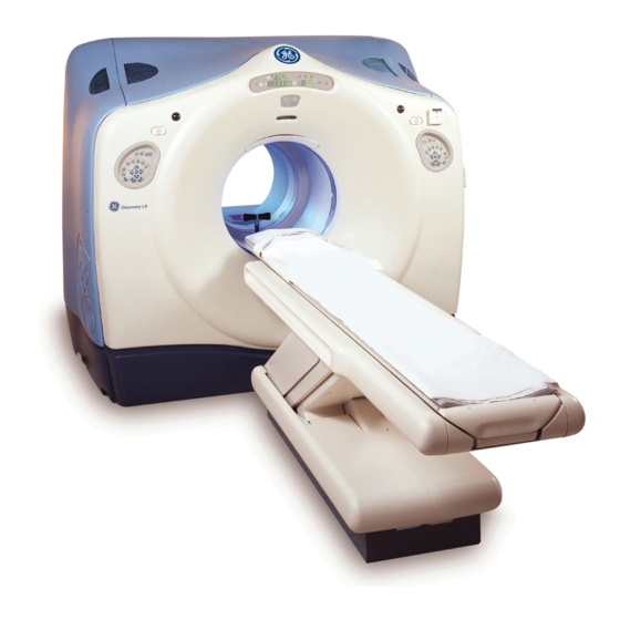
Specification, Direction 2103139-100. Introduction The Discovery LS product is the first combined CT-PET system introduced by GE that combines diagnostic quality CT with premium PET. This imaging system is based on the Advance PET and the LightSpeed Plus (4-Slice), LightSpeed Ultra (8-Slice), or LightSpeed 16 (16-Slice) CT GE systems. -
Page 80: Pdu
GE H EALTHCARE 2307224-100, R LS S IRECTION EVISION ISCOVERY YSTEM ERVICE ANUAL 3.2.1 CT Systems used with the DLS may have either a Compact PDU (CPDU) or the shorter New Global PDU (NGPDU). Refer to Figure 3-9. The PDU distributes system power. Power travels from the PDU to the Gantry. -
Page 81: Slip-Ring Infrastructure
HEALTHCARE 2307224-100, R LS S IRECTION EVISION ISCOVERY YSTEM ERVICE ANUAL 3.2.7 Slip-Ring Infrastructure The slip-ring infrastructure consists of the following architecture: • 4 CU Rings for STC/OBC Communications • 2 RF Rings for DAS data transfer • 3 CU Rings for Safety Interlock •... -
Page 82: Detector Ring
The radioactive sources are used for calibration and attenuation correction. Electrical Requirements The Discovery LS combined CT-PET system has separate electrical requirements for the CT and PET. These requirements are exactly the same requirements for the Advance PET and the LightSpeed CT systems. -
Page 83: Patient Table
700 mm clearance for service access between the two gantries. CT-PET LAN (Local Area Network) The Discovery LS LAN is a common CT-PET network that integrates both the CT and the PET original LAN networks. It carries data and commands between all of the subsystems: OWS PET, WS CT, Table, Gantry CT, Gantry PET, SHARC and EDCAT. -
Page 84: Figure 3-3: Original Ct And Pet Network
GE H EALTHCARE 2307224-100, R LS S IRECTION EVISION ISCOVERY YSTEM ERVICE ANUAL Figure 3-3: Original CT and PET Network Page 84 Chapter 3 - DLS System Functional Description... -
Page 85: Figure 3-4: Integrated Ct And Pet Networks (Option 1)
HEALTHCARE 2307224-100, R LS S IRECTION EVISION ISCOVERY YSTEM ERVICE ANUAL Figure 3-4: Integrated CT and PET Networks (Option 1) Chapter 3 - DLS System Functional Description Page 85... -
Page 86: Figure 3-5: Integrated Ct And Pet Networks (Option 2)
GE H EALTHCARE 2307224-100, R LS S IRECTION EVISION ISCOVERY YSTEM ERVICE ANUAL Figure 3-5: Integrated CT and PET Networks (Option 2) Page 86 Chapter 3 - DLS System Functional Description... -
Page 87: Lan Connections For Systems With Turbosharc
HEALTHCARE 2307224-100, R LS S IRECTION EVISION ISCOVERY YSTEM ERVICE ANUAL 3.7.1 LAN Connections for Systems with TurboSHARC This section describes the LAN connections between the PET and CT systems, the hospital DICOM network, and the Xeleris workstation for systems with Turbo SHARC. Figure 3-6: LAN Connections for Systems with Turbo SHARC Chapter 3 - DLS System Functional Description Page 87... -
Page 88: Figure 3-7: Turbo Sharc Cabinet Selections
GE H EALTHCARE 2307224-100, R LS S IRECTION EVISION ISCOVERY YSTEM ERVICE ANUAL Figure 3-7: Turbo SHARC Cabinet Selections Page 88 Chapter 3 - DLS System Functional Description... -
Page 89: E-Stop Safety
HEALTHCARE 2307224-100, R LS S IRECTION EVISION ISCOVERY YSTEM ERVICE ANUAL Workstation SHARC Backplane Optical Drive Data Tape Drive RS232 Terminal Server Bulkhead SCSI GANTRY EDCAT Backplane Figure 3-8: RS232 PET Connection with Turbo SHARC E-Stop Safety Another circuit that was integrated in the CT and PET subsystems is the CT and PET hardware Emergency Stop. -
Page 90: Figure 3-9: Electrical Block Diagram
GE H EALTHCARE 2307224-100, R LS S IRECTION EVISION ISCOVERY YSTEM ERVICE ANUAL Figure 3-9: Electrical Block Diagram Page 90 Chapter 3 - DLS System Functional Description... -
Page 91: Figure 3-10: Data Flow / Control Block Diagram
HEALTHCARE 2307224-100, R LS S IRECTION EVISION ISCOVERY YSTEM ERVICE ANUAL Figure 3-10: Data Flow / Control Block Diagram Chapter 3 - DLS System Functional Description Page 91... -
Page 92: Figure 3-11: Grounding Diagram
GE H EALTHCARE 2307224-100, R LS S IRECTION EVISION ISCOVERY YSTEM ERVICE ANUAL Figure 3-11: Grounding Diagram Page 92 Chapter 3 - DLS System Functional Description... -
Page 93: System Start-Up
HEALTHCARE 2307224-100, R LS S IRECTION EVISION ISCOVERY YSTEM ERVICE ANUAL 3.10 System Start-Up System start-up comprises the following steps: 1.) Power up the PET computer. 2.) Power up the CT computer, the Scan monitor and the Image monitor. Note: System start-up as described below, activates all firmware, the CT subsystems and the CT and PET host computers. -
Page 94: Powering Up The Pet Peripherals And Subsystems
GE H EALTHCARE 2307224-100, R LS S IRECTION EVISION ISCOVERY YSTEM ERVICE ANUAL 3.10.1 Powering Up the PET Peripherals and Subsystems In case it is necessary to power up the PET peripherals and subsystem, follow the instructions below: To power up the PET peripherals and subsystems: Make sure that the Voltage Select Switch is set to the correct voltage and the Circuit Breaker CB12 is On (both located in front of the cabinet). -
Page 95: Switching To The Pet User Interface Display On The Scan Monitor
HEALTHCARE 2307224-100, R LS S IRECTION EVISION ISCOVERY YSTEM ERVICE ANUAL 3.10.2 Switching to the PET User Interface Display on the Scan Monitor The Scan Monitor is used to display either the CT or the PET user interface. The default view of the Scan Monitor is the CT prescription. -
Page 96: System Shut-Down
GE H EALTHCARE 2307224-100, R LS S IRECTION EVISION ISCOVERY YSTEM ERVICE ANUAL 3.11 System Shut-Down The PET firmware and subsystems can be shut down using the procedure described in Section 3.11.2 The PET-CT software is shut down at two levels: •... -
Page 97: Switching Off Power To Pet Subsystems And Peripherals
HEALTHCARE 2307224-100, R LS S IRECTION EVISION ISCOVERY YSTEM ERVICE ANUAL a.) To turn off the system, press the [Power] button on the CT computer. Power button Figure 3-15: CT Computer b.) To restart the system, click [Restart] or press any key on the keyboard. 4.) To shutdown the PET computer, press the [Power] button on the Sun computer. -
Page 98: Shutting Down The Ct And Pet Applications
GE H EALTHCARE 2307224-100, R LS S IRECTION EVISION ISCOVERY YSTEM ERVICE ANUAL Electronics Cabinet, to the Off position. Figure 3-17: PDU Circuit Breaker Switches 3.11.3 Shutting Down the CT and PET Applications The applications can be shut down, leaving the host computers operating systems as well as all firmware and subsystems running. -
Page 99: Figure 3-19: Service Desktop Showing Utilities/Tools Menu
HEALTHCARE 2307224-100, R LS S IRECTION EVISION ISCOVERY YSTEM ERVICE ANUAL To shut down the CT and PET applications: 1.) From the Desktop Selection Area on the Image Monitor (right monitor), click the [Shutdown] button (Figure 3-18). The Service Desktop displays. 2.) Click the [Toolboxes/Utilities] button. -
Page 100: Resetting Ct Subsystems
GE H EALTHCARE 2307224-100, R LS S IRECTION EVISION ISCOVERY YSTEM ERVICE ANUAL 3.11.4 Resetting CT Subsystems Reset any of the CT subsystems using the following procedure: 1.) Click the [Service] icon on the desktop. The Service Desktop displays. System Reset Button Figure 3-20: CT Service Desktop 2.) From the Service Desktop, click the [System Reset] button. -
Page 101: Rebooting Pet Subsystems
HEALTHCARE 2307224-100, R LS S IRECTION EVISION ISCOVERY YSTEM ERVICE ANUAL 3.11.5 Rebooting PET Subsystems The individual PET Advance subsystems may be rebooted by typing the corresponding acronym into the "terminate -reboot" command line. The command line accepts multiple subsystem acronyms, separated by a space. - Page 102 GE H EALTHCARE 2307224-100, R LS S IRECTION EVISION ISCOVERY YSTEM ERVICE ANUAL Page 102 Chapter 3 - DLS System Functional Description...
-
Page 103: Service Desktop, Tools And Diagnostics
HEALTHCARE 2307224-100, R LS S IRECTION EVISION ISCOVERY YSTEM ERVICE ANUAL Chapter 4 - Service Desktop, Tools and Diagnostics More information about the features described in this section can be found in the following manuals: • LightSpeed 2.X System Service Manual, Direction 2243314-100 (for 4-slice SDAS Systems) •... -
Page 104: Service Desktop Main Menu
GE H EALTHCARE 2307224-100, R LS S IRECTION EVISION ISCOVERY YSTEM ERVICE ANUAL 4.1.1 Service Desktop Main Menu The Service Desktop is the entry point for all service tools and diagnostics. The desktop is designed with nine major functional tools each with its own purpose: •... -
Page 105: Service Desktop Functionality
HEALTHCARE 2307224-100, R LS S IRECTION EVISION ISCOVERY YSTEM ERVICE ANUAL 4.1.2 Service Desktop Functionality The users of the Service Desktop have different needs than the technologists, radiologists, doctors, and other users of the system. Therefore, the functionality for the Service Desktop differs from that of the other desktops. -
Page 106: Figure 4-4: Systems Reset
GE H EALTHCARE 2307224-100, R LS S IRECTION EVISION ISCOVERY YSTEM ERVICE ANUAL Refer to Figure 4-4. The System Resets function allows resetting and downloading the scanner hardware as required to prepare the system for the scanning operation. Access Systems Resets as follows: 1.) Select Systems Resets from the Service Desktop. -
Page 107: Chapter 5 Console
HEALTHCARE 2307224-100, R LS S IRECTION EVISION ISCOVERY YSTEM ERVICE ANUAL Chapter 5 - Console For service information and procedures for the CT console components, refer to the following manuals: • LightSpeed 2.X System Service Manual, Direction 2243314-100 (for 4-slice SDAS Systems) •... -
Page 108: Figure 5-1: Locations Of Console Components (H2 Shown)
GE H EALTHCARE 2307224-100, R LS S IRECTION EVISION ISCOVERY YSTEM ERVICE ANUAL Communications between the CT Host and SRU take place primarily using a network channel and serial connections. Using the network channel allows sharing of resources on the CT Host disk by the SRU (client). -
Page 109: Console Connections
HEALTHCARE 2307224-100, R LS S IRECTION EVISION ISCOVERY YSTEM ERVICE ANUAL Console Connections Figure 5-3: Console Block Diagram (H2 Shown) Chapter 5 - Console Page 109... - Page 110 GE H EALTHCARE 2307224-100, R LS S IRECTION EVISION ISCOVERY YSTEM ERVICE ANUAL Page 110 Chapter 5 - Console...
-
Page 111: Chapter 6 Table
HEALTHCARE 2307224-100, R LS S IRECTION EVISION ISCOVERY YSTEM ERVICE ANUAL Chapter 6 - Table CT-PET Table Functional Description 6.1.1 Table Overview The patient table is a common CT-PET subsystem used for both acquisition procedures. The table positions the patient in the imager’s Field of View (FOV). The table moves in the cradle horizontal and vertical axes for patient positions. -
Page 112: Manual Table
• 2352370: Roller Cover Collector • 2331112: Cover Table - CT Cover Interface • 2277548: Plug Side Cover H2 • 2371256-100: Discovery LS ME1 to ME1.5 Table Upgrade FMI Instruction 6.2.1.2 Required Tools In addition to the standard tool kit, the following tools are needed: •... -
Page 113: Before Beginning
HEALTHCARE 2307224-100, R LS S IRECTION EVISION ISCOVERY YSTEM ERVICE ANUAL 6.2.2 Before Beginning Before the system is shut down to begin this upgrade, raise the table to its maximum height. 6.2.3 Pre-Mechanical Installation Follow the procedures in this section to prepare the system for the Mechanical Installation Team. CAUTION The FE must be present to warm-up the system, take initial measurements, shut down, and lock-out/tag-out the system. -
Page 114: Mechanical Installation
GE H EALTHCARE 2307224-100, R LS S IRECTION EVISION ISCOVERY YSTEM ERVICE ANUAL 6.2.4 Mechanical Installation There will be parts left over after completing this upgrade. 6.2.4.1 Remove the Table Covers 1.) Refer to Figure 6-1. Remove all the metal covers from the secondary base. (Follow local facility guidelines to discard or recycle the metal base covers.) -
Page 115: Figure 6-3: Remove The Table Side Covers
HEALTHCARE 2307224-100, R LS S IRECTION EVISION ISCOVERY YSTEM ERVICE ANUAL 3.) Refer to Figure 6-3. Remove the table top side covers. (Each side cover is held in place with two quarter-turn captive screws, located on the under the table top.) 4.) Refer to Figure 6-3. -
Page 116: Figure 6-4: Remove The Side Elevator Covers
GE H EALTHCARE 2307224-100, R LS S IRECTION EVISION ISCOVERY YSTEM ERVICE ANUAL b.) Refer to Figure 6-4. Use a 1/8 inch Allen wrench to remove the two screws and ground braid that fasten each cover into place. c.) Remove the elevator covers and set aside. -
Page 117: Figure 6-5: Remove The Etc Cover
HEALTHCARE 2307224-100, R LS S IRECTION EVISION ISCOVERY YSTEM ERVICE ANUAL 6.) Refer to Figure 6-5. Remove the ETC cover. a.) If necessary, use a flat-blade screwdriver to loosen the two captive thumb screws that fasten the cover into place. b.) Set the cover aside. -
Page 118: Remove The Base Cover Brackets
GE H EALTHCARE 2307224-100, R LS S IRECTION EVISION ISCOVERY YSTEM ERVICE ANUAL 8.) Refer to Figure 6-7. Use a 1/8 inch Allen wrench to remove the four screws that fasten the Elevator/Tilt Drive Assembly cover into place. 9.) Set the cover and hardware aside. -
Page 119: Figure 6-9: Characterization Calibration Bracket
HEALTHCARE 2307224-100, R LS S IRECTION EVISION ISCOVERY YSTEM ERVICE ANUAL 3.) Refer to Figure 6-9. Remove the characterization bracket, located near the fans on the right front corner of the ETC chassis. a.) Use a 5 mm Allen wrench to remove the M6 socket-head cap screw that fastens the characterization calibration bracket into place. -
Page 120: Figure 6-11: Remove The Tab From The Calibration Bar
GE H EALTHCARE 2307224-100, R LS S IRECTION EVISION ISCOVERY YSTEM ERVICE ANUAL c.) Refer to Figure 6-11. * If the Calibration Bar has a metal tab on the left side of the bar, proceed to Step * If the Calibration Bar does not have a metal tab on the left side of the bar, proceed to Section 6.2.4.3. -
Page 121: Install The Mechanical Stop Assembly
HEALTHCARE 2307224-100, R LS S IRECTION EVISION ISCOVERY YSTEM ERVICE ANUAL 6.2.4.3 Install the Mechanical Stop Assembly At least four versions of the Secondary Base currently exist in the field. Some versions contain both a front and rear mechanical stop, some contain a single front or rear stop, and at least one version has no mechanical stops at all. -
Page 122: Remove The Manual Control Hardware
GE H EALTHCARE 2307224-100, R LS S IRECTION EVISION ISCOVERY YSTEM ERVICE ANUAL Note: The kit may contain a pre-assembled mechanical stop. If not, use Figure 6-13 as a guide to assemble a mechanical stop for your system. If the table has no mechanical stops, locate and remove the following parts from the kit:... -
Page 123: Unfasten And Remove The Cables
6-14. Use a 3 mm Allen wrench to remove the three socket-head cap screws that fasten the KB box to the bracket on the casting. 2.) Return the KB Box (and clutch motor casting) to GE Headquarters. Chapter 6 - Table... -
Page 124: Remove The Pedal Assembly
GE H EALTHCARE 2307224-100, R LS S IRECTION EVISION ISCOVERY YSTEM ERVICE ANUAL 6.2.5.4 Remove the Pedal Assembly 1.) Refer to Figure 6-15. Use a 6 mm Allen wrench to remove the two socket-head cap screws that fasten the pedal to the side of the table base. -
Page 125: Remove The Switch Rail
HEALTHCARE 2307224-100, R LS S IRECTION EVISION ISCOVERY YSTEM ERVICE ANUAL 3.) Refer to Figure 6-17. Use a 6 mm Allen wrench to remove the CT and PET position limit switches from the table. (Each limit switch fastens to the table with two socket-head cap screws.) Remove the switch rail. -
Page 126: Disconnect And Discard The Ct-Pet Positions Cable (P/N 2318721)
GE H EALTHCARE 2307224-100, R LS S IRECTION EVISION ISCOVERY YSTEM ERVICE ANUAL 6.2.5.7 Disconnect and Discard the CT-PET Positions Cable (P/N 2318721) The ETC I/F J8 connection consists of three cables and a pigtail. Two cables go to the PET and CT limit switches, and one cable goes to the Gantry. -
Page 127: Remove The Cable Harness (P/N 2271256) From The Table
HEALTHCARE 2307224-100, R LS S IRECTION EVISION ISCOVERY YSTEM ERVICE ANUAL 6.2.5.8 Remove the Cable Harness (P/N 2271256) from the Table The ETC I/F J8 connection consists of three cables and a pigtail. Two cables go to the PET and CT limit switches and one cable goes to the Gantry. -
Page 128: Remove The Intf Sw And Cl Cont I Cable (P/N 2309066) From The Table
GE H EALTHCARE 2307224-100, R LS S IRECTION EVISION ISCOVERY YSTEM ERVICE ANUAL 6.2.5.9 Remove the INTF SW and CL CONT I Cable (P/N 2309066) from the Table Some versions of the M1 Table do not have Table bulkheads. The cables attach directly to the cable connections in the table retractor. -
Page 129: Remove The Motor Clutch Assembly (P/N 2309067)
HEALTHCARE 2307224-100, R LS S IRECTION EVISION ISCOVERY YSTEM ERVICE ANUAL 6.2.5.10 Remove the Motor Clutch Assembly (P/N 2309067) For best results, check the table and secondary base with a level before removing the motor clutch assembly. Check level again, before fastening the covers into place. If necessary, adjust the table levelers to re-level the table and secondary base. -
Page 130: Assemble And Attach The Spreader Bar Assembly
GE H EALTHCARE 2307224-100, R LS S IRECTION EVISION ISCOVERY YSTEM ERVICE ANUAL 6.2.5.11 Assemble and Attach the Spreader Bar Assembly 1.) Locate and remove the following Spreader Bar Assembly components from the kit: Quantity Part Number Description 2356111 Spreader Bar... -
Page 131: Figure 6-25: Secondary Base Spreader Bar Clamped Into Place
HEALTHCARE 2307224-100, R LS S IRECTION EVISION ISCOVERY YSTEM ERVICE ANUAL 3.) Refer to Figure 6-25. Clamp the Side Pieces of the Spreader Bar to the secondary base rails. (Do not remove any table anchors.) 4.) Tighten the Spreader Bar bolts. Figure 6-25: Secondary Base Spreader Bar Clamped into Place 5.) Refer to Figure... -
Page 132: Install The Automated Base Hardware
GE H EALTHCARE 2307224-100, R LS S IRECTION EVISION ISCOVERY YSTEM ERVICE ANUAL 7.) Refer to Figure 6-27. Use a 13 mm or 1/2 in. socket wrench to remove: a.) Five bolts that fasten the motor clutch assembly to the right Secondary Base side rail. -
Page 133: Determine The Right Secondary Base Rail Revision
HEALTHCARE 2307224-100, R LS S IRECTION EVISION ISCOVERY YSTEM ERVICE ANUAL 6.2.6.2 Determine the Right Secondary Base Rail Revision Determine the secondary base revision by counting the number of access holes in the right rail while facing the Gantry. All tables use the CT Drill Template. •... -
Page 134: Attach The Ct Template And Drill The Hole(S)
GE H EALTHCARE 2307224-100, R LS S IRECTION EVISION ISCOVERY YSTEM ERVICE ANUAL 6.2.6.3 Attach the CT Template and Drill the Hole(s) All table revisions use the CT template. Follow the instructions in this section to attach the CT Drill Template, P/N 2355224, to the right secondary base side rail. -
Page 135: Figure 6-31: Fasten Ct Drill Template To Right Rail Exterior
HEALTHCARE 2307224-100, R LS S IRECTION EVISION ISCOVERY YSTEM ERVICE ANUAL 2.) Refer to Figure 6-31. (The CT Drill Template attaches to the exterior of the side rail through the "A" holes just tapped.) Use a 3 mm Allen wrench to fasten two M4 socket-head cap bolts (P/N 328417P7) through the template. -
Page 136: Determine The Pet Detent Location
GE H EALTHCARE 2307224-100, R LS S IRECTION EVISION ISCOVERY YSTEM ERVICE ANUAL 6.2.6.4 Determine the PET Detent Location The specified distance between the CT scan plane and PET scan plane equals 675 mm +/-14 mm. For the PET detent holes drilled into the Revision 3 rail and the PET plugs (Revision 0, 1, and 2), position the PET detent 675 mm from the CT detent. -
Page 137: Attach The Pet Template And Drill The Standard Pet Detent Holes
HEALTHCARE 2307224-100, R LS S IRECTION EVISION ISCOVERY YSTEM ERVICE ANUAL 6.2.6.5 Attach the PET Template and Drill the Standard PET Detent Holes Revision 0, 1 and 2 tables use the PET Drill template. Revision 3 tables do not use this template. Follow the instructions in this section to attach the PET Drill Template, P/N 2355334, to the right secondary base side rail. -
Page 138: Figure 6-33: Pet Drill Template (Exterior View)
GE H EALTHCARE 2307224-100, R LS S IRECTION EVISION ISCOVERY YSTEM ERVICE ANUAL 4.) Refer to Figure 6-33. Fasten the template into place with the two clamp blocks and four sets of M6 hardware. 5.) Use a 5 mm Allen wrench to tighten the M6 hardware. -
Page 139: Fasten Pet Detent Offset Template (P/N 2371258) To Revision 3 Rail
HEALTHCARE 2307224-100, R LS S IRECTION EVISION ISCOVERY YSTEM ERVICE ANUAL 6.2.6.6 Fasten PET Detent Offset Template (P/N 2371258) to Revision 3 Rail If the distance between the PET and CT scan planes on the system is less than 661 mm, a new set of PET detent and PET detent adjuster holes must be drilled closer to the CT detent. -
Page 140: Fasten The Pet Detent Offset Template To The Revision 0, 1 Or 2 Rail
GE H EALTHCARE 2307224-100, R LS S IRECTION EVISION ISCOVERY YSTEM ERVICE ANUAL 6.2.6.7 Fasten the PET Detent Offset Template to the Revision 0, 1 or 2 Rail If the distance between the PET and CT scan planes on the system is less than 661 mm, a new set of PET detent and PET detent adjuster holes must be drilled closer to the CT detent. -
Page 141: Drill A New Set Of Pet Detent Holes 10Mm Closer To The Ct Detent
HEALTHCARE 2307224-100, R LS S IRECTION EVISION ISCOVERY YSTEM ERVICE ANUAL 6.2.6.8 Drill a New Set of PET Detent Holes 10mm Closer to the CT Detent Follow the instructions in this section if the distance between PET and CT scan planes falls between 651 and 661mm. -
Page 142: Install The New Clutch Motor Assembly
GE H EALTHCARE 2307224-100, R LS S IRECTION EVISION ISCOVERY YSTEM ERVICE ANUAL 5.) Vacuum all debris from the area. These holes shift the PET detent adjuster 20 mm. These holes shift the PET detent 20 mm closer to the CT detent. -
Page 143: Install The Table Bulkhead (If Necessary)
HEALTHCARE 2307224-100, R LS S IRECTION EVISION ISCOVERY YSTEM ERVICE ANUAL 3.) Use a 13 mm or 1/2 inch socket to reattach the new assembly to the secondary base. a.) Fasten the motor clutch assembly to the right secondary base side rail with five bolts. b.) Fasten the motor clutch assembly to the left secondary base side rail with four bolts. -
Page 144: Install The Base Axis Motor I Cable (P/N 2323724)
GE H EALTHCARE 2307224-100, R LS S IRECTION EVISION ISCOVERY YSTEM ERVICE ANUAL 6.2.6.12 Install the Base Axis Motor I Cable (P/N 2323724) Install the Base Axis Motor I Cable between J11 on the rear of the table bulkhead and the J5 connector on the Cradle Tilt/Elevation Driver Assembly. -
Page 145: Install The Clutch Control I Cable (P/N 2340390)
HEALTHCARE 2307224-100, R LS S IRECTION EVISION ISCOVERY YSTEM ERVICE ANUAL 6.2.6.13 Install the Clutch Control I Cable (P/N 2340390) Install the Clutch Control Cable from the rear of the Table bulkhead (J12) to the (future) Clutch Driver Unit location before installing the Clutch Driver Unit. 1.) Insert the J12 connector of Cable P/N 2340390 into the rear of the Table bulkhead. -
Page 146: Install Clutch Driver Unit (P/N 2340282)
GE H EALTHCARE 2307224-100, R LS S IRECTION EVISION ISCOVERY YSTEM ERVICE ANUAL 6.2.6.14 Install Clutch Driver Unit (P/N 2340282) Follow the instructions in this section to install the Clutch Driver Unit, P/N 2340282. CAUTION Refer to Figure 6-43. The Clutch Driver Unit bracket may require modification to fit into the space provided by filing the holes or grinding the edge of the bracket. -
Page 147: Install The Clutch Driver Unit Power Cable (P/N 2338088)
HEALTHCARE 2307224-100, R LS S IRECTION EVISION ISCOVERY YSTEM ERVICE ANUAL 6.2.6.15 Install the Clutch Driver Unit Power Cable (P/N 2338088) Refer to Figure 6-45. Make a mental note of the wire color before disconnecting A1 and A2 on the ETC ASM side of the filter. -
Page 148: Attach The Ground Wire (P/N 2338084) To The Clutch Driver Unit
GE H EALTHCARE 2307224-100, R LS S IRECTION EVISION ISCOVERY YSTEM ERVICE ANUAL 5.) Refer to Figure 6-47. Reattach the filter wires to the filter. a.) Attach the black wire to the left side of the filter. b.) Attach the white wire to the right side of the filter. -
Page 149: Replace The Etc Interface Board
4.) Remove the new ETC I/F Board from its static protection bag and fasten it into place. 5.) Place the old ETC I/F Board into the static protection bag, and follow local guidelines to return the board to GE. 6.) Fasten the ETC I/F cables back into place. -
Page 150: Install The Base Cmd Adapter Cable (P/N 2338086)
GE H EALTHCARE 2307224-100, R LS S IRECTION EVISION ISCOVERY YSTEM ERVICE ANUAL 6.2.6.18 Install the Base CMD Adapter Cable (P/N 2338086) The next series of cables originate or terminate at the ETC Board. For best results, route the cables under the ETC mounting tray before connecting them to the ETC Board. -
Page 151: Install The Ct-Pet Position Optical Sensor (P/N 2350570)
HEALTHCARE 2307224-100, R LS S IRECTION EVISION ISCOVERY YSTEM ERVICE ANUAL 6.2.6.19 Install the CT-PET Position Optical Sensor (P/N 2350570) For best results, route P/N 2350570 under the ETC Board before making the connection. 1.) Locate and remove the CT-PET Position Optical Sensor from the kit. 2.) Refer to Figure 6-52. -
Page 152: Install The Base Driver Enable Ribbon Cable (P/N 2340386)
GE H EALTHCARE 2307224-100, R LS S IRECTION EVISION ISCOVERY YSTEM ERVICE ANUAL 6.) Refer to Figure 6-54 (shows the cable tie-off to J14 on the main ETC Board). Tie-wrap the old J8 connector to another cable on the ETC assembly to keep it out of the way. -
Page 153: Figure 6-56: Attach New Ribbon Cable To Etc I/F J4
HEALTHCARE 2307224-100, R LS S IRECTION EVISION ISCOVERY YSTEM ERVICE ANUAL 2.) Refer to Figure 6-56. Attach the ETC I/F J4 side of the Base Drive Enable Cable, P/N 2340386, to the ETC I/F J4 connector. Connect new cable to J4. Figure 6-56: Attach New Ribbon Cable to ETC I/F J4 3.) Refer to Figure... -
Page 154: Figure 6-58: Connect New Ribbon Cable To Existing Ribbon Cable
GE H EALTHCARE 2307224-100, R LS S IRECTION EVISION ISCOVERY YSTEM ERVICE ANUAL 4.) Refer to Figure 6-58. Connect the existing ribbon cable, P/N 2271251, to the adapter side of the new Base Drive Enable ribbon cable, P/N 2340386. Figure 6-58: Connect New Ribbon Cable to Existing Ribbon Cable 5.) Refer to... -
Page 155: Install Base Cmd Adapter (P/N 2304737)
HEALTHCARE 2307224-100, R LS S IRECTION EVISION ISCOVERY YSTEM ERVICE ANUAL 6.2.6.21 Install Base CMD Adapter (P/N 2304737) Refer to Figure 6-60. The CMD adapter has three connectors with captive hardware. It is difficult to attach the existing cable with the CMD Adapter fastened onto the ETC I/F Board. It is easier to attach the existing cable to the back of the CMD Adaptor before attaching the adaptor to the ETC I/F Board. -
Page 156: Figure 6-62: Attach Existing Signal Harness To J1 On Cmd Adapter
GE H EALTHCARE 2307224-100, R LS S IRECTION EVISION ISCOVERY YSTEM ERVICE ANUAL 2.) Refer to Figure 6-62. Attach the Signal Harness J7 connector to CMD Adapter J1, and tighten the screws. Attach existing J7 cable to CMD Adapter before fastening the CMD Adaptor in place. -
Page 157: Attach Flanges (P/N 2320158) To The Secondary Base
HEALTHCARE 2307224-100, R LS S IRECTION EVISION ISCOVERY YSTEM ERVICE ANUAL 4.) Refer to Figure 6-64. Attach the Base CMD Adaptor Cable, P/N 2338086, to J2 of the CMD Adapter, and tighten the screws. (The Base CMD Adapter Cable, P/N 2338086 was installed in Section 6.2.6.18. -
Page 158: Figure 6-65: Left Cover Flange With Adhesive Tie-Wrap Mounts
GE H EALTHCARE 2307224-100, R LS S IRECTION EVISION ISCOVERY YSTEM ERVICE ANUAL CAUTION To prevent potential interference during table base motion, ALWAYS orient the mounts as shown in Figure 6-65. ALWAYS remove the protective backing, and use the adhesive base to fasten the mounts to the left rail flange. -
Page 159: Attach Clutch Motor Cables
HEALTHCARE 2307224-100, R LS S IRECTION EVISION ISCOVERY YSTEM ERVICE ANUAL 4.) Refer to Figure 6-66. Attach three tie-wrap mounts, P/N 46-208747P2, to the front end of the table rail. (If possible, align each adhesive mount to a pre-drilled and tapped M5 hole.) 5.) Orient the mounts vertically as shown in Figure 6-65, and wipe the area with alcohol to ensure... -
Page 160: Figure 6-68: Route Clutch Motor Cables Beneath Front Of Table
GE H EALTHCARE 2307224-100, R LS S IRECTION EVISION ISCOVERY YSTEM ERVICE ANUAL a.) Attach Base Potentiometer E, P/N 2323729, to J1 of the bulkhead. (Refer to Figure 6-69. Cable P/N 2323729 has a pigtail permanently attached to the gantry end of the cable.) b.) Attach Clutch Control E, P/N 2323726, to J2 of the bulkhead. -
Page 161: Reassemble The Secondary Base Drive Belt
HEALTHCARE 2307224-100, R LS S IRECTION EVISION ISCOVERY YSTEM ERVICE ANUAL 2. Refer to Figure 6-69. Be careful when making the gantry connections. Look for the connectors in the harness next to the lower left front quadrant of the gantry. •... -
Page 162: Figure 6-71: Drive Belt Fastener Plate
GE H EALTHCARE 2307224-100, R LS S IRECTION EVISION ISCOVERY YSTEM ERVICE ANUAL 2.) Refer to Figure 6-71. Wrap the belt around the two drive pulleys, and bring the ends together over the fastener plate. Clamp belt into place over the fastener plate (shown with clamp hardware). -
Page 163: Figure 6-73: Reassemble The Drive Belt
HEALTHCARE 2307224-100, R LS S IRECTION EVISION ISCOVERY YSTEM ERVICE ANUAL 4.) Refer to Figure 6-73. Position the belt so the marks on the belt line up with the edges of the belt clamp. (Orient the belt clamp with the smooth surface facing up and the corrugated side against the teeth on the belt.) 5.) Use a 4 mm Allen wrench to fasten the clamp into place with four sets of belt clamp hardware. -
Page 164: Set The Table Position Pot
GE H EALTHCARE 2307224-100, R LS S IRECTION EVISION ISCOVERY YSTEM ERVICE ANUAL 6.2.6.25 Set the Table Position Pot Follow the procedure in this section to set up and secure the table position pot that is attached to the Clutch Motor casting. -
Page 165: Attach The Ct-Pet Position Latch Mounting Plate
HEALTHCARE 2307224-100, R LS S IRECTION EVISION ISCOVERY YSTEM ERVICE ANUAL 6.2.6.26 Attach the CT-PET Position Latch Mounting Plate NOTICE Two types of linear rail bearing blocks exist in the field. The size of the pre-drilled and tapped holes in the bearing blocks determines the type of mounting plate to use. The kit contains both plates and both sets of hardware. -
Page 166: Install The Pet-Ct Position Latch Assembly
GE H EALTHCARE 2307224-100, R LS S IRECTION EVISION ISCOVERY YSTEM ERVICE ANUAL NOTICE Do not install the plate backward. 3.) Orient the plate as shown in Figure 6-77. • The edge of the plate with two holes faces the rear of the table. -
Page 167: Figure 6-79: Ct-Pet Latch In Position
HEALTHCARE 2307224-100, R LS S IRECTION EVISION ISCOVERY YSTEM ERVICE ANUAL 2.) Locate and remove following hardware from the upgrade kit: Part Number Description Quantity 2340721 GS Positioning Unit (CT-PET Position Latch Assembly) 46-328417P13 M6 x 16 mm Hexagon Socket Screw 2315373-4 M6 Lock Washer 2109878-3... -
Page 168: Install The Ct And Pet Detent/Flag Assemblies
GE H EALTHCARE 2307224-100, R LS S IRECTION EVISION ISCOVERY YSTEM ERVICE ANUAL 6.2.6.28 Install the CT and PET Detent/Flag Assemblies The CT-PET Position Latch rolls into two detents that attach to the right side rail. The first time, the detents are attached directly to the rail. -
Page 169: If A Pet Plug Is Required
HEALTHCARE 2307224-100, R LS S IRECTION EVISION ISCOVERY YSTEM ERVICE ANUAL 6.2.6.29 If a PET Plug Is Required 1.) Refer to Figure 6-81. If working with a Revision 0, 1, or 2 table rail, the PET Plug, P/N 2342038, is installed in the fifth access hole from the front of the table. Revision 0 Side Rail (Seven Access Holes) PET plug in fifth Access hole. -
Page 170: If A Ct Plug Is Required
GE H EALTHCARE 2307224-100, R LS S IRECTION EVISION ISCOVERY YSTEM ERVICE ANUAL 6.2.6.30 If a CT Plug Is Required 1.) Refer to Figure 6-83. If working with a Revision 0 rail, the CT Plug, P/N 2342039, is installed in the seventh access hole from the front of the table. -
Page 171: Install The Ct Detent And Flag Assembly
HEALTHCARE 2307224-100, R LS S IRECTION EVISION ISCOVERY YSTEM ERVICE ANUAL 6.2.6.31 Install the CT Detent and Flag Assembly Refer to Figure 6-85. The CT Detent Flag Assembly fastens to right rear table rail with two M5 mounting bolts. The CT detent is fixed in place and provides the table Z-Axis reference. Flag Use a 4 mm Allen wrench to fasten M5 mounting bolts. -
Page 172: Install The Pet Detent And Flag Assembly
GE H EALTHCARE 2307224-100, R LS S IRECTION EVISION ISCOVERY YSTEM ERVICE ANUAL 6.2.6.32 Install the PET Detent and Flag Assembly The PET Detent/Flag assembly attaches near the middle of the right table rail with three M5 mounting bolts. Center the bolts in the slots when fastening the PET Detent/Flag assembly to the rail. -
Page 173: Assemble And Install Pet Detent Adjuster
HEALTHCARE 2307224-100, R LS S IRECTION EVISION ISCOVERY YSTEM ERVICE ANUAL 4. Refer to Figure 6-87. a.) If necessary, loosen the flag hardware, and turn the adjusters to center the flag over the notch in the CT and PET detent. b.) Measure the distance between the leading edges of the CT and PET flags. -
Page 174: Shim The Pet Detent Assembly
GE H EALTHCARE 2307224-100, R LS S IRECTION EVISION ISCOVERY YSTEM ERVICE ANUAL 3.) Refer to Figure 6-89. Use a 3 mm Allen wrench to fasten the adjuster block to the side rail. 4.) Adjust the set screw until it just touches the PET detent. -
Page 175: Figure 6-90: Check Relationship Between Roller Arm And Pin Out Of Detent
HEALTHCARE 2307224-100, R LS S IRECTION EVISION ISCOVERY YSTEM ERVICE ANUAL 2.) Refer to Figure 6-90. Check the relationship between the roller arm and position latch pin. • A gas spring provides the roller arm tension. • Whenever the CT-PET position latch is out of the detent, the roller arm rests against the latch pin, as shown in the Figure 6-90 detail. -
Page 176: Figure 6-92: Check Relationship Between Roller Arm And Pin In The Detent
GE H EALTHCARE 2307224-100, R LS S IRECTION EVISION ISCOVERY YSTEM ERVICE ANUAL 4.) Refer to Figure 6-92. Push the table into the detent, and check the roller arm. (A gap of at least 0.5 mm should exist between the roller arm and latch pin. -
Page 177: Install Optical Sensor (P/N 2350570)
HEALTHCARE 2307224-100, R LS S IRECTION EVISION ISCOVERY YSTEM ERVICE ANUAL 6.2.6.35 Install Optical Sensor (P/N 2350570) CAUTION Refer to Figure 6-93. To prevent damage to the optical sensor, temporarily fasten it into place with one screw. After the sensor mounting bracket is adjusted and the clearance checked, fasten the sensor into place with both screws. -
Page 178: Figure 6-95: Align The Optical Sensor To The Flag
GE H EALTHCARE 2307224-100, R LS S IRECTION EVISION ISCOVERY YSTEM ERVICE ANUAL 5.) Refer to Figure 6-95. Check for clearance between the optical sensor and the flag plate. (Refer Figure 6-94. If the optical sensor touches the top or bottom surface of the flag plate, bend the optical sensor bracket until the distances from the sensor to the flag plate surfaces appear equal.) -
Page 179: Align The Flag Plates To The Optical Sensor
HEALTHCARE 2307224-100, R LS S IRECTION EVISION ISCOVERY YSTEM ERVICE ANUAL 6.2.6.36 Align the Flag Plates to the Optical Sensor Follow the procedure in this section to align the flag to the optical sensor. 1.) Refer to Figure 6-96. When the optical sensor is over the flag, the edges are not visible. Use a pencil or marker to mark the edges of the flag on both flag plates. -
Page 180: Install The Table Latch
GE H EALTHCARE 2307224-100, R LS S IRECTION EVISION ISCOVERY YSTEM ERVICE ANUAL 6.2.6.37 Install the Table Latch 1.) Refer to Figure 6-98. Locate and remove the Table Latch Assembly from the upgrade kit. During normal operation, the latch holds the table in the patient loading (CT) position. -
Page 181: Figure 6-100: Fasten Service Latch To Table Rail With Three Sets Of M5 Hardware
HEALTHCARE 2307224-100, R LS S IRECTION EVISION ISCOVERY YSTEM ERVICE ANUAL 3.) Locate and remove the following hardware that matches the table rail revision from the upgrade kit: Part Number Description Quantity Table Revision 46-214695P23 M5 x 12 mm Socket-Head Cap Screw If Revision 3 46-328432P8 M5 Lock Washer... -
Page 182: Adjust The Table Latch
GE H EALTHCARE 2307224-100, R LS S IRECTION EVISION ISCOVERY YSTEM ERVICE ANUAL 6.2.6.38 Adjust the Table Latch Follow the procedure in this section to adjust the CT-PET Position assembly and Table Latch. 1.) Push the table into the CT position. Lower the Table Latch bar and pin into place. -
Page 183: Figure 6-103: Reposition The Solenoid
HEALTHCARE 2307224-100, R LS S IRECTION EVISION ISCOVERY YSTEM ERVICE ANUAL 3.) If the 3 mm clearance cannot be obtained between the bottom of the Table latch and the CT-PET Position Latch Arm, reposition the solenoid. a.) Refer to Figure 6-103. -
Page 184: Figure 6-105: Adjust The Solenoid Spring
GE H EALTHCARE 2307224-100, R LS S IRECTION EVISION ISCOVERY YSTEM ERVICE ANUAL 5.) Refer to Figure 6-105. Use a 2.5 mm Allen wrench to loosen the solenoid spring bracket. Lift up latch arm. Screws on Solenoid Spring Bracket Figure 6-105: Adjust the Solenoid Spring 6.) Refer to... -
Page 185: Install The New Characterization Bracket
HEALTHCARE 2307224-100, R LS S IRECTION EVISION ISCOVERY YSTEM ERVICE ANUAL 6.2.6.39 Install the New Characterization Bracket NOTICE Install this bracket BEFORE the fourth Top Cover bracket is installed. (See Section 6.2.6.40.) 1.) Locate and remove the following parts from the upgrade kit: Part Number Description Quantity... -
Page 186: Install The Top Cover Brackets
GE H EALTHCARE 2307224-100, R LS S IRECTION EVISION ISCOVERY YSTEM ERVICE ANUAL 6.2.6.40 Install the Top Cover Brackets NOTICE Do NOT install the fourth cover bracket until the characterization bracket is installed. 1.) Refer to Figure 6-108. Use a 5 mm Allen wrench to fasten three of the four top cover brackets to the ETC Assembly. -
Page 187: Install The Fourth Top Cover Bracket
HEALTHCARE 2307224-100, R LS S IRECTION EVISION ISCOVERY YSTEM ERVICE ANUAL 6.2.6.41 Install the Fourth Top Cover Bracket 1.) Locate and remove the following hardware from the installation kit: Part Number Description Quantity 2332371 Cover Bracket (Right Rear) 46-328417P4 M4 x 12 mm Socket-Head Cap Screw 46-328432P2 M4 Lock Washer 46-328430P2... -
Page 188: Install The Cosmetic Cradle Caps
GE H EALTHCARE 2307224-100, R LS S IRECTION EVISION ISCOVERY YSTEM ERVICE ANUAL NOTICE The captive screw at the bottom of the ETC mounting tray is rounded to fit easily into the connector. Pivot the ETC mounting tray into place, and push down until the captive screw drops into place. -
Page 189: Install Table Secondary Base Covers
HEALTHCARE 2307224-100, R LS S IRECTION EVISION ISCOVERY YSTEM ERVICE ANUAL 6.2.7 Install Table Secondary Base Covers Follow the procedure in this section to attach the covers to the Secondary Base of the Automated Table. All Secondary Base cover hardware currently ships in a large plastic bag. For best results, sort and inventory the hardware before you start to attach the brackets to the table base. - Page 190 GE H EALTHCARE 2307224-100, R LS S IRECTION EVISION ISCOVERY YSTEM ERVICE ANUAL 6.2.7.2 Table Cover and Bracket Task List Note: All the drawings in this section are shown without the upper table assembly. Refer to Figure 6-112. Assemble the lower table covers and brackets in the following order: 1.) Install the roller cover assembly:...
-
Page 191: Install The Roller Cover Assembly
HEALTHCARE 2307224-100, R LS S IRECTION EVISION ISCOVERY YSTEM ERVICE ANUAL 6.2.7.3 Install the Roller Cover Assembly CAUTION The roller canister is too small to accommodate a cover long enough to stretch to the service position. After the roller cover assembly is installed and the roller cover attached to the bracket on the table, REMEMBER to detach the cover each time the table is moved to the service position. -
Page 192: Figure 6-114: Secondary Base Side Rail Slot Locations
GE H EALTHCARE 2307224-100, R LS S IRECTION EVISION ISCOVERY YSTEM ERVICE ANUAL 3.) Refer to Figure 6-114. Locate the slots that will be used to fasten the cover guides to the inside surface of the secondary table base. Insert screws from the outside. -
Page 193: Attach The Cover Bracket To The Secondary Base
HEALTHCARE 2307224-100, R LS S IRECTION EVISION ISCOVERY YSTEM ERVICE ANUAL 6.2.7.5 Attach the Cover Bracket to the Secondary Base Follow the procedure in this section to attach the cover bracket to the secondary base and align it to the roller cover guides. 1.) The cover bracket shares the same holes and hardware as the cable retractor bracket. -
Page 194: Reposition The Ground Bus Bar
GE H EALTHCARE 2307224-100, R LS S IRECTION EVISION ISCOVERY YSTEM ERVICE ANUAL 4.) Refer to Figure 6-118. Lay a ruler or the flat edge of an allen wrench across the top of the bracket to the lower cover guide rail. -
Page 195: Attach Canister Brackets To Head End Of The Secondary Base
HEALTHCARE 2307224-100, R LS S IRECTION EVISION ISCOVERY YSTEM ERVICE ANUAL 6.2.7.7 Attach Canister Brackets to Head End of the Secondary Base 1.) Locate and remove the Right Canister Bracket Assembly, P/N 2332626-2, and the Left Canister Bracket Assembly, P/N 2332626, from the upgrade kit. (The canister brackets are mirror images.) 2.) Refer to Figure... -
Page 196: Attach The Drip Trough To The Roller Canister Assembly
GE H EALTHCARE 2307224-100, R LS S IRECTION EVISION ISCOVERY YSTEM ERVICE ANUAL 6.2.7.8 Attach the Drip Trough to the Roller Canister Assembly The drip trough diverts fluids away from the roller canister assembly, and onto the floor. 1.) Refer to Figure 6-121. -
Page 197: Attach The Roller Cover Canister To The Secondary Base
HEALTHCARE 2307224-100, R LS S IRECTION EVISION ISCOVERY YSTEM ERVICE ANUAL 6.2.7.9 Attach the Roller Cover Canister to the Secondary Base For best results, use two people to install the Roller Cover Canister, P/N 2331848. Use a 5 mm Allen wrench to fasten the canister assembly to the table with four sets of the following M6 hardware: •... -
Page 198: Install The Idler Roller And Align It To The Roller Cover Guides
GE H EALTHCARE 2307224-100, R LS S IRECTION EVISION ISCOVERY YSTEM ERVICE ANUAL 6.2.7.10 Install the Idler Roller and Align it to the Roller Cover Guides 1.) Locate and remove the idler roller, P/N 2331848, from the kit. 2.) Refer to Figure 6-123. -
Page 199: Figure 6-125: Align Idler Roller To Roller Cover Guides
HEALTHCARE 2307224-100, R LS S IRECTION EVISION ISCOVERY YSTEM ERVICE ANUAL 5.) Refer to Figure 6-125. Roller adjustments: a.) Rest an Allen wrench or ruler between the top of the idle roller and the top surface of the lower roller cover guide. b.) Raise or lower the idler roller in its slot, until the top of the roller is even with the top surface of the lower roller cover guide. -
Page 200: Figure 6-127: Check Cover Clearances
GE H EALTHCARE 2307224-100, R LS S IRECTION EVISION ISCOVERY YSTEM ERVICE ANUAL 8.) To close the cover: a.) Slide the roller cover toward the table while you slide the table forward. b.) Use a 4 mm Allen wrench to fasten the cover into place with three M6 x 12 flat-head screws, P/N 2103580-12. -
Page 201: Fasten The Side Skirts To The Secondary Base
HEALTHCARE 2307224-100, R LS S IRECTION EVISION ISCOVERY YSTEM ERVICE ANUAL 6.2.7.11 Fasten the Side Skirts to the Secondary Base Four side skirts and a back cap enclose the bottom of the secondary base. Attach the longer right and left side covers to the secondary base first, then attach the front right and left side covers. Do not fasten the back cap into place until the rear top covers are installed. -
Page 202: Figure 6-129: Side Covers - Exploded View
GE H EALTHCARE 2307224-100, R LS S IRECTION EVISION ISCOVERY YSTEM ERVICE ANUAL CAUTION Refer to Figure 6-129. Do NOT install the bottom cover screw between the PET and CT Detents, on the right side of the table. This screw will interfere with the table travel between the two positions, causing the table to jolt as the latch rolls over the head of the screw. -
Page 203: Attach The Interface Cover Between The Dls Table And Gantry
HEALTHCARE 2307224-100, R LS S IRECTION EVISION ISCOVERY YSTEM ERVICE ANUAL c.) Refer to Figure 6-130. Fit the front side covers over the long side covers. Use screwdriver or bolt to prevent the cover from retracting into the canister. Attach Rear Side Covers first. Front Side Cover overlaps rear cover. -
Page 204: Fasten The Rear Covers To The Secondary Base
GE H EALTHCARE 2307224-100, R LS S IRECTION EVISION ISCOVERY YSTEM ERVICE ANUAL 6.2.7.13 Fasten the Rear Covers to the Secondary Base The Top Cover attaches directly to the table, and travels with the table as it moves between the PET and CT detents. -
Page 205: Attach The Top Cap Assembly To The Secondary Base
HEALTHCARE 2307224-100, R LS S IRECTION EVISION ISCOVERY YSTEM ERVICE ANUAL 6.2.7.14 Attach the Top Cap Assembly to the Secondary Base Refer to Figure 6-134. The Top Cap Assembly, P/N 2320161, attaches to the foot end of the secondary base, and rests on flanges attached to the side rails. When the table moves back to the CT detent, the metal Table Top Cover, P/N 2333078, slides beneath the Top Cap Assembly. -
Page 206: Attach The Back Cap To The Foot End Of The Secondary Base
GE H EALTHCARE 2307224-100, R LS S IRECTION EVISION ISCOVERY YSTEM ERVICE ANUAL 6.2.7.15 Attach the Back Cap to the Foot End of the Secondary Base Follow the procedure in this section to attach the back cover brackets and the Back Cap to the foot end of the secondary base. -
Page 207: Figure 6-136: Back Cap (P/N2320164) Rear View W/ Profile Bracket
HEALTHCARE 2307224-100, R LS S IRECTION EVISION ISCOVERY YSTEM ERVICE ANUAL 3.) Refer to Figure 6-136 Figure 6-137. Locate and remove the Back Cap, P/N 2320164, from the kit. Figure 6-136: Back Cap (P/N2320164) Rear View w/ Profile Bracket Chapter 6 - Table Page 207... -
Page 208: Finish The Mechanical Installation
GE H EALTHCARE 2307224-100, R LS S IRECTION EVISION ISCOVERY YSTEM ERVICE ANUAL 4.) Mount the Back Cap on the Motor Base. Make sure that the flange of the Back Profile clips into the Top Cap, as shown in Figure 6-137. -
Page 209: Figure 6-138: Me 1.5 Table Block Diagram
HEALTHCARE 2307224-100, R LS S IRECTION EVISION ISCOVERY YSTEM ERVICE ANUAL Figure 6-138: ME 1.5 Table Block Diagram Chapter 6 - Table Page 209... -
Page 210: Completion
GE H EALTHCARE 2307224-100, R LS S IRECTION EVISION ISCOVERY YSTEM ERVICE ANUAL 6.2.9 Completion This section contains the instructions for the Field Engineer. 1.) Refer to Figure 6-139. If new Gantry keypads were shipped, install them at this time. (The new keypads replace the gantry tilt buttons with PET and CT position buttons.) -
Page 211: Direction 2307224-100, Revision Discovery Ls System Service Manual
HEALTHCARE 2307224-100, R LS S IRECTION EVISION ISCOVERY YSTEM ERVICE ANUAL 17.) Refer to Figure 6-140. Click TABLE TYPE Autobase. Figure 6-140: Hardware Configuration Panel 18.) Click ACCEPT to close the panel with the current selections. 19.) Restart applications. 20.) Flash download: a.) Click the SERVICE icon to open the Service Desktop. -
Page 212: Figure 6-141: Final Pet And Ct Flag Adjustment
GE H EALTHCARE 2307224-100, R LS S IRECTION EVISION ISCOVERY YSTEM ERVICE ANUAL e.) Select MECHANICAL CHARACTERIZATION. f.) Select BASE, and follow the on screen instructions. g.) Manually push the table to the CT position. If the table is already in the CT position, push it off the detent and push it back into place. -
Page 213: Manual Table Wiring
HEALTHCARE 2307224-100, R LS S IRECTION EVISION ISCOVERY YSTEM ERVICE ANUAL Adjusting Screw Loosen hardware with 2.5 mm Allen wrench. Figure 6-142: Adjust PET Flag 8. Return to Step 21. Characterize the base for the second time. 9. Run another hardware reset. 10. -
Page 214: Figure 6-144: 2338513Sch
GE H EALTHCARE 2307224-100, R LS S IRECTION EVISION ISCOVERY YSTEM ERVICE ANUAL Figure 6-144: 2338513SCH Page 214 Chapter 6 - Table... -
Page 215: Troubleshooting Tips
HEALTHCARE 2307224-100, R LS S IRECTION EVISION ISCOVERY YSTEM ERVICE ANUAL Troubleshooting Tips 6.3.1 Potentiometer Counts Differ 6.3.1.1 Symptom Potentiometer (pot) counts differ by fewer than 100 counts when the table base moves from CT to PET. 6.3.1.2 Probable Causes and Suggestions Refer to Figure 6-139 Figure... -
Page 216: Ct-Pet Position Latch Solenoid Fails To Engage
GE H EALTHCARE 2307224-100, R LS S IRECTION EVISION ISCOVERY YSTEM ERVICE ANUAL 6.3.2 CT-PET Position Latch Solenoid Fails to Engage 6.3.2.1 Symptom Refer to Figure 6-78 page 166. The CT-PET Position Latch Solenoid fails to engage. 6.3.2.2 Probable Causes and Suggestions 1.) Bad solenoid. -
Page 217: Gantry Does Not Run System Light Tests
HEALTHCARE 2307224-100, R LS S IRECTION EVISION ISCOVERY YSTEM ERVICE ANUAL 6.3.7 Gantry Does Not Run System Light Tests 6.3.7.1 Symptom The gantry will not run the system light tests during initial power up. 6.3.7.2 Probable Causes and Suggestions Motor Clutch assembly cable improperly connected. Check the Y-cable connections to the gantry harness. -
Page 218: Replacing The Secondary Base Front Pulley
GE H EALTHCARE 2307224-100, R LS S IRECTION EVISION ISCOVERY YSTEM ERVICE ANUAL 2.) Refer to Figure 6-147. Loosen the four screws holding the timing belt clamp, and remove the clamp with the belt. Clamp Screws (4) Belt Ends Figure 6-147: Timing Belt Clamp 3.) Insert the new timing belt over the pulley and through the slot in the cam rollers block. -
Page 219: Replacing The Secondary Base Motor
HEALTHCARE 2307224-100, R LS S IRECTION EVISION ISCOVERY YSTEM ERVICE ANUAL 6.5.3 Replacing the Secondary Base Motor 1.) Loosen the two coupling screws. (Refer to 1 in Figure 6-148 for position; screws are not shown.) Figure 6-148: Secondary Base Motor - General View 2.) Remove the four screws holding the motor on the motor base. -
Page 220: Figure 6-150: Motor Assembly And Coupling Removed
GE H EALTHCARE 2307224-100, R LS S IRECTION EVISION ISCOVERY YSTEM ERVICE ANUAL 5.) Refer to Figure 6-150. Remove the motor assembly. Figure 6-150: Motor Assembly and Coupling Removed 6.) Take the new motor, insert the coupling, and push the coupling to the motor flange. -
Page 221: Replacing The Secondary Base Motor Coupling
HEALTHCARE 2307224-100, R LS S IRECTION EVISION ISCOVERY YSTEM ERVICE ANUAL 6.5.4 Replacing the Secondary Base Motor Coupling 1.) Loosen the two coupling screws. (See 1 in Figure 6-148 for position; screws not shown.) 2.) Remove the four screws holding the motor on the motor base. (See 2 in Figure 6-148). - Page 222 GE H EALTHCARE 2307224-100, R LS S IRECTION EVISION ISCOVERY YSTEM ERVICE ANUAL Page 222 Chapter 6 - Table...
-
Page 223: Chapter 7 Gantry
2286765-100, Chapter 1, Section 2 - Gantry. CT-PET Gantry Functional Description 7.1.1 Mechanical Description The Discovery LS gantry is built from two main building blocks: • CT Gantry – LightSpeed Plus (4-slice), LightSpeed Ultra (8-slice), or LightSpeed 16 (16-slice) • PET Gantry – PET Advance... -
Page 224: Gantry Transport Mechanism
GE H EALTHCARE 2307224-100, R LS S IRECTION EVISION ISCOVERY YSTEM ERVICE ANUAL 7.1.2.1 Gantry Transport Mechanism Refer to Figure 7-1. The PET and the CT Gantries are installed close to one another. In order to enable service access for the gantries, the PET gantry is installed on a set of rollers on one side and a linear bearing assembly on the other. -
Page 225: Gantry-Table Cable Routing
One of the major concerns in connecting two different systems, such as the LightSpeed CT and the PET Advance, is with the need for registration between the images. Discovery LS uses a combination of software and mechanical registration techniques. Image registration is initially based on a mechanical registration of both gantries, such that the isocenter of both gantries is located along the same line. -
Page 226: Electrical Description
7.1.3 Electrical Description The CT and PET gantries operate as sub-systems of the overall Discovery LS system and are connected through the system Ethernet LAN. The functionality of each gantry subsystem remains the same as in stand-alone PET Advance and CT LightSpeed installations. -
Page 227: Pet Gantry Replacement Procedures
HEALTHCARE 2307224-100, R LS S IRECTION EVISION ISCOVERY YSTEM ERVICE ANUAL PET Gantry Replacement Procedures For repair procedures for the Advance PET gantry components: Refer to the Advance PET Imaging Repair Procedures, Direction 2100323. 7.5.1 PET Gantry Drive Mechanism Replacement (P/N 2290248) The PET Gantry drive mechanism is shown in Figure 7-3. -
Page 228: Figure 7-5: Pet Gantry Drive Mechanism Sub-Assemblies (View 1)
GE H EALTHCARE 2307224-100, R LS S IRECTION EVISION ISCOVERY YSTEM ERVICE ANUAL 2.) Refer to Figure 7-5. To assemble the new unit, put the tracking Trapezoidal Nut, P/N 2294692, into the Nut Bearing Housing, P/N HB60002064. Distances Tracking Trapezoidal Screw... -
Page 229: Figure 7-6: Pet Gantry Drive Mechanism Sub-Assemblies (View 2)
HEALTHCARE 2307224-100, R LS S IRECTION EVISION ISCOVERY YSTEM ERVICE ANUAL 4.) Refer to Figure 7-6. Assemble the Nut Rotation Stopper, P/N 2299099, onto the Tracking Trapezoidal Nut using four M4 x 10 mm screws. Note: All screws are assembled with flat and lock washers. 5.) Take the assembled unit and fasten it to the Driving Nut Holder, P/N 2294699, using two M10 x 30 mm screws. -
Page 230: Figure 7-7: Driving Mechanism - External Assembly
GE H EALTHCARE 2307224-100, R LS S IRECTION EVISION ISCOVERY YSTEM ERVICE ANUAL 7.) Refer to Figure 7-7. Assemble the small Nut Bearing Housing, P/N HB60002014, to the Tracking Bearing Basis using two M8 x 16 mm screws. Retaining Ring Bearing Housing Figure 7-7: Driving Mechanism –... -
Page 231: Gantry Cables Or Retractor Replacement
HEALTHCARE 2307224-100, R LS S IRECTION EVISION ISCOVERY YSTEM ERVICE ANUAL 11.) Grease the end of the trapezoidal screw, insert the tracking trapezoidal screw into the flange, and assemble the unit on the adjustable baseplate using three M6 x 10 mm screws. Loosely tighten these screws. -
Page 232: Figure 7-10: Retractors Mechanical Connection (General View 1)
GE H EALTHCARE 2307224-100, R LS S IRECTION EVISION ISCOVERY YSTEM ERVICE ANUAL Figure 7-10: Retractors Mechanical Connection (General View 1) Figure 7-11: Retractors Mechanical Connection (General View 2) Page 232 Chapter 7 - Gantry... -
Page 233: Replacing The External Retractor Or Its Cables
HEALTHCARE 2307224-100, R LS S IRECTION EVISION ISCOVERY YSTEM ERVICE ANUAL 7.5.2.1 Replacing the External Retractor or its Cables The 14 AEDI Cables, P/N 46-325061, are routed through the external retractor as illustrated in Figure 7-12. AEDI AEDI AEDI AEDI AEDI AEDI AEDI... -
Page 234: Figure 7-13: Placing Cable Inside Retractor
GE H EALTHCARE 2307224-100, R LS S IRECTION EVISION ISCOVERY YSTEM ERVICE ANUAL 5.) Refer to Figure 7-13. Replace and lay the cables inside the retractor. The length of each cable that protrudes from the side to which the bracket is assembled is given in Table 7-1. -
Page 235: Figure 7-14: External Retractor Connected To Legs Crossbeam
HEALTHCARE 2307224-100, R LS S IRECTION EVISION ISCOVERY YSTEM ERVICE ANUAL 8.) Refer to Figure 7-14 Figure 7-15. Fold the retractor and connect the bracket to the legs crossbeam using four M6 x 20 mm screws. External Retractor Bracket Clips Legs Crossbeam Length of Protruding... -
Page 236: Replacing The Internal Retractor Or Its Cables
GE H EALTHCARE 2307224-100, R LS S IRECTION EVISION ISCOVERY YSTEM ERVICE ANUAL 7.5.2.2 Replacing the Internal Retractor or its Cables The following cables are routed through the internal retractor as shown in Figure 7-16. RS232 ETHERNET ETHERNET FIBER-OPTIC INSIDE THE... - Page 237 HEALTHCARE 2307224-100, R LS S IRECTION EVISION ISCOVERY YSTEM ERVICE ANUAL 5.) Refer to Figure 7-13. Replace and lay the cables inside the retractor. The length of each cable that protrudes from the side to which the bracket is assembled is given in Table 7-2.
-
Page 238: Figure 7-17: External And Internal Retractors Connected To Legs Crossbeam
GE H EALTHCARE 2307224-100, R LS S IRECTION EVISION ISCOVERY YSTEM ERVICE ANUAL 8.) Refer to Figure 7-17 Figure 7-18. Fold the retractor and connect the bracket to the legs crossbeam using four 6 x 20 mm screws. External Retractor... -
Page 239: Connecting External Pet Cables & New Ct-Pet Cables To New A36-1, A36-2, A37-1
HEALTHCARE 2307224-100, R LS S IRECTION EVISION ISCOVERY YSTEM ERVICE ANUAL 7.5.3 Connecting External PET Cables & New CT-PET Cables to New A36-1, A36-2, A37-1 Panels • The external PET cables and the new CT-PET cables are connected to the new A36-1, A36- 2, and A37-1 brackets as shown in Figure 7-19. -
Page 240: Replacement Of The Short Positioning Pin (P/N 2287052)
GE H EALTHCARE 2307224-100, R LS S IRECTION EVISION ISCOVERY YSTEM ERVICE ANUAL 7.5.4 Replacement of the Short Positioning Pin (P/N 2287052) 1.) Refer to Figure 7-21. Remove the four screws holding the pin base. Screw (4) on Pin Base... -
Page 241: Procedures And Adjustments
HEALTHCARE 2307224-100, R LS S IRECTION EVISION ISCOVERY YSTEM ERVICE ANUAL Procedures and Adjustments 7.6.1 Removing the Covers for PET Gantry Service Movement 1.) Refer to Figure 7-23. Open the two locks on the Rear Bottom Cover, and pull the cover out. CT Right Side Cover Bottom Right Cover Rear Bottom Cover... - Page 242 GE H EALTHCARE 2307224-100, R LS S IRECTION EVISION ISCOVERY YSTEM ERVICE ANUAL Page 242 Chapter 7 - Gantry...
-
Page 243: System Qc, Calibration And Functional Tests
As a prerequisite to the VQC calibration procedure, the secondary base of the table must be initially aligned. For a full description of the initial table alignment, refer to the Discovery LS Installation Manual, Direction 2289039-100, Section 5.2.2 - Initial Table Positioning. -
Page 244: Reset The Software Alignment Parameters
GE H EALTHCARE 2307224-100, R LS S IRECTION EVISION ISCOVERY YSTEM ERVICE ANUAL 8.1.1.2 Reset the Software Alignment Parameters The following procedure explains how to reset (set to default values) the software alignment parameters. The software realignment procedure uses the definition of CT Reconstruction (X, Y, Pan) and the Z-cradle motion parameters, which it takes from configuration files. -
Page 245: Scanning And Reconstructing The Vqc Phantom
HEALTHCARE 2307224-100, R LS S IRECTION EVISION ISCOVERY YSTEM ERVICE ANUAL 8.1.1.4 Scanning and Reconstructing the VQC Phantom Important - Prerequisite for Scanning VQC Phantom: The image quality is very important for the accuracy of the measurements and for calibration. The CT and PET systems must be fully calibrated and blank scans for CT and PET must be updated. -
Page 246: Figure 8-4: Patient Information Screen
GE H EALTHCARE 2307224-100, R LS S IRECTION EVISION ISCOVERY YSTEM ERVICE ANUAL 3.) Refer to Figure 8-4. In the opened Patient Information screen, enter the following: • Patient ID: VQC, current date, and test number, for example: VQC_8_13_N1. • Patient Name: Same as Patient ID. -
Page 247: Figure 8-5: Selecting The Protocol
HEALTHCARE 2307224-100, R LS S IRECTION EVISION ISCOVERY YSTEM ERVICE ANUAL 4.) Refer to Figure 8-5. Click below the patient’s legs in the Protocol Selection area, and choose the Volumetric QC protocol from the drop-down menu. The Volumetric QC protocol can be selected by clicking under the feet in the picture of the patient. -
Page 248: Vqc Processing And Software Realignment
GE H EALTHCARE 2307224-100, R LS S IRECTION EVISION ISCOVERY YSTEM ERVICE ANUAL 8.1.1.5 VQC Processing and Software Realignment 1.) Set the system into PET mode by clicking the [PET] icon on the Image Monitor desktop area. The Scan Monitor displays the PET main screen. -
Page 249: Figure 8-8: Images Database Navigator Showing Image Sets List
HEALTHCARE 2307224-100, R LS S IRECTION EVISION ISCOVERY YSTEM ERVICE ANUAL 5.) Refer to Figure 8-8. From the Patient List, click the entry representing the calibration acquisition. A list of image sets displays. Image Image Figure 8-8: Images Database Navigator Showing Image Sets List 6.) From the Image Sets list in Figure 8-8, select the two image sets that represent the CT and... - Page 250 GE H EALTHCARE 2307224-100, R LS S IRECTION EVISION ISCOVERY YSTEM ERVICE ANUAL Service personnel should ignore these messages and proceed to mechanical realignment in Section 8.1.1.6. Image Alignment Table The Image Alignment Table shows the accuracy of alignment between PET and CT images. The alignment results are calculated for the phantom landmarks in the center of FOV and 20 cm from the center of FOV.
-
Page 251: Mechanical Alignment Table
ANUAL 8.1.1.6 Mechanical Alignment Table Important: Mechanical alignment must only be performed by a GE qualified service engineer. 1.) Choose Options from the Volumetric QC Panel. 2.) Choose Show Mechanical Calibration from the drop-down list. The Mechanical Calibration parameters (shown in Figure 8-10) display in the Planes Alignment Panel. -
Page 252: Options
Based on the Mechanical Calibration Table described in Section 8.1.1.5, table and gantry alignment adjustments are now performed NOTICE Service corrections to the plane alignment adjusters may only be performed by a qualified GE Service Engineer. 8.1.2.1 .Aligning the Table Align the table according to the Gantry Alignment Table as follows: 1.) Move the Secondary Base PET Positioning Block by the Z distance that is indicated in the... -
Page 253: Gantry Alignment Prerequisites
HEALTHCARE 2307224-100, R LS S IRECTION EVISION ISCOVERY YSTEM ERVICE ANUAL 2.) Refer to Figure 8-11. After adjustment, make sure that the Z Adjustment Screw is firmly positioned against the PET Positioning Block, and tighten the three screws loosened earlier. Loosen 3 screws. -
Page 254: Preparing The Gantry For Adjustment
GE H EALTHCARE 2307224-100, R LS S IRECTION EVISION ISCOVERY YSTEM ERVICE ANUAL 4.) Loosen the screws on the driving assembly holding bracket (shown in Figure 8-14), and remove the holding bracket from the leg of the gantry enabling the gantry to move freely along its transport rails. -
Page 255: Figure 8-15: Securing Screws On Rollers
HEALTHCARE 2307224-100, R LS S IRECTION EVISION ISCOVERY YSTEM ERVICE ANUAL 2.) Unscrew all the baseplate screws (shown in Figure 8-14) sufficiently to take the pressure off the spring washers and allow the baseplate to be adjusted. 3.) Move the gantry to the middle of its travel range. 4.) Make sure that the securing screws (shown in Figure 8-15) on the high-load roller adjusters... -
Page 256: Aligning The Gantry
GE H EALTHCARE 2307224-100, R LS S IRECTION EVISION ISCOVERY YSTEM ERVICE ANUAL 8.1.2.4 Aligning the Gantry 1.) Raise the Gantry left side dolly until the front high-load roller clears the floor (5 mm minimum). Note: When raising the Gantry, always lift the left side first and lower it last. -
Page 257: Figure 8-18: Mechanical Stoppers Adjustment Screws
HEALTHCARE 2307224-100, R LS S IRECTION EVISION ISCOVERY YSTEM ERVICE ANUAL 11.) Refer to Figure 8-18. Move the gantry to its home position, and secure it to the mechanical stoppers, adjusting the screws of the mechanical stoppers as follows: a.) Remove screws marked 2. b.) Loosen screws marked 1. - Page 258 YSTEM ERVICE ANUAL For Discovery LS systems, the following changes to this procedure should be made: 1.) The alignment of the phantom is performed using the inner laser light only. Landmarks should be defined only with the inner laser light in the CT position.
-
Page 259: Planned Maintenance (Pm)
ANUAL Chapter 9 - Planned Maintenance (PM) In addition to the maintenance procedures for the new Discovery LS components described on the following pages, the maintenance schedules for the CT and the PET components included in the system as detailed in the documents listed hereunder, must be followed carefully: •... -
Page 260: Lubrication Of Pet Gantry Driving Mechanism
GE H EALTHCARE 2307224-100, R LS S IRECTION EVISION ISCOVERY YSTEM ERVICE ANUAL 9.1.1 Lubrication of PET Gantry Driving Mechanism The recommended grease used for the PET gantry linear rail and the secondary base rails: Grease Lithium THK AFB, Catalog Number: CH060000120. -
Page 261: Greasing The Pet Gantry Linear Bearings
HEALTHCARE 2307224-100, R LS S IRECTION EVISION ISCOVERY YSTEM ERVICE ANUAL 9.1.1.4 Greasing the PET Gantry Linear Bearings Figure 9-1: Greasing the Linear Bearings 1.) Remove the screw or grease fitting from the lubrication points. 2.) If necessary, clean the linear rail using medical alcohol. 3.) Attach a grease gun to the grease fittings and fill them with 2.9 g (three full grease pumps) of AFB grease. -
Page 262: Maintenance Of Cables And Connectors
ISCOVERY YSTEM ERVICE ANUAL Maintenance of Cables and Connectors Table 9-1 provides descriptions and frequencies of the Discovery LS procedures for maintenance of cables and connectors. Table 9-3: Maintenance Procedures of Cables and Connectors Description of Procedure Frequency Comment Visual inspection and verification of all table bulkhead connections. -
Page 263: Electrical Connections
Systems) • LightSpeed 4.X Schematics Manual, Direction 2341962-100 (for 16-slice MDAS Systems) 10.1 Power and Data Cables Checklist The following sections contain tables that list all the cables connecting the Discovery LS subsystems. 10.1.1 CT Electronics Cabinet The cables that connect to the CT Electronics cabinet are Red Coded. -
Page 264: Pet Electronics Cabinet
GE H EALTHCARE 2307224-100, R LS S IRECTION EVISION ISCOVERY YSTEM ERVICE ANUAL 10.1.2 PET Electronics Cabinet Table 10-2: PET Electronics Cabinet Cables Cable Connector Part Number Destination Notes Service Outlets CAB1 A3 46-311772P1 Gantry Includes Power TS 8 Ground... -
Page 265: Discovery Ls Console
HEALTHCARE 2307224-100, R LS S IRECTION EVISION ISCOVERY YSTEM ERVICE ANUAL 10.1.3 Discovery LS Console Table 10-3: Discovery LS Console Cables Cable Connector Part Number Destination Notes SHARC-OWS Cable OWS1 A6 46-311828G3 Pet PDU Serial 3 Magic-OWS Cable OWS1 A6... -
Page 266: Manual Table Retractor Cables
IRECTION EVISION ISCOVERY YSTEM ERVICE ANUAL 10.1.4 Table Retractor Cables 10.1.4.1 Manual Table Retractor Cables Table 10-4: Discovery LS Dynamic Table Cables (Manual Tables) Cable Connector Part Number Destination Table I/F J1 EXT Table Bulkhead 2295952 CT Gantry (Cable 2265881-2) -
Page 267: Automated And Extended Table Retractor Cables
LS S IRECTION EVISION ISCOVERY YSTEM ERVICE ANUAL 10.1.4.2 Automated and Extended Table Retractor Cables Table 10-5: Discovery LS Dynamic Table Cables (Automated & Extended Tables) Cable Connector Part Number Destination Table I/F J1 EXT Table Bulkhead 2295952 CT Gantry... -
Page 268: Secondary Base Cables
Bulkhead J12 CT-PET Positions ETC I/F J8 2318721 Pedal Mechanism 10.1.5.2 Automated and Extended Table Secondary Base Cables Table 10-7: Discovery LS Static Table Cables (Automated and Extended Tables) Cable Connector Part Number Destination Secondary Base (SB) Ground Screw 2340388... -
Page 269: Ct Gantry Cables
HEALTHCARE 2307224-100, R LS S IRECTION EVISION ISCOVERY YSTEM ERVICE ANUAL 10.1.6 CT Gantry Cables The cables that connect to the CT Gantry are Blue Coded. 10.1.6.1 CT Gantry Cables – Manual Table Table 10-8: CT Gantry Cables (Manual Tables) Part Cable Connector... -
Page 270: Ct Gantry Cables - Automated And Extended Table
GE H EALTHCARE 2307224-100, R LS S IRECTION EVISION ISCOVERY YSTEM ERVICE ANUAL 10.1.6.2 CT Gantry Cables – Automated and Extended Table Table 10-9: CT Gantry Cables (Automated and Extended Tables) Part Cable Connector Destination Notes Number Scan Interlock 2271060... -
Page 271: Pet Gantry
HEALTHCARE 2307224-100, R LS S IRECTION EVISION ISCOVERY YSTEM ERVICE ANUAL 10.2 PET Gantry Table 10-10: PET Gantry Cables Part Number Part Number Cable Connector Destination (Tilt Version) (Non Tilt Version) AEDI A37-1 J17 46-325061P1 2121185 PET PDU CAB1 A3 J7 AEDI A37-1 J18 46-325061P1... -
Page 272: Wiring Diagrams
Base Axis Motor M KB Box Table Motor Note 1 - See Discovery LS Site Preparation Manual, Direction 2317947-100, Section 6.3.7. Note 2 - See one of the following appropriate manuals: • LightSpeed 2.X Installation Manual, Direction 2243312-100 (for 4-slice SDAS Systems) •... -
Page 273: Automated And Extended Table Grounding Connections
Base Axis Motor M SB Connector Bracket Table Motor Note 1 - See Discovery LS Site Preparation Manual, Direction 2317947-100, Section 6.3.7. Note 2 - See one of the following appropriate manuals: • LightSpeed 2.X Installation Manual, Direction 2243312-100 (for 4-slice SDAS Systems) •... -
Page 274: Figure 10-1: Discovery Ls Grounding Connections (Manual And Automated Tables)
GE H EALTHCARE 2307224-100, R LS S IRECTION EVISION ISCOVERY YSTEM ERVICE ANUAL Figure 10-1: Discovery LS Grounding Connections (Manual and Automated Tables) Page 274 Chapter 10 - Electrical Connections... -
Page 275: Ct Cable Connections
HEALTHCARE 2307224-100, R LS S IRECTION EVISION ISCOVERY YSTEM ERVICE ANUAL 10.3.2 CT Cable Connections Figure 10-2: CT System with H2 Interconnect Diagram (Manual Tables) Chapter 10 - Electrical Connections Page 275... -
Page 276: Figure 10-3: Ct System With Goc1 & Cpdu Interconnect Diagram (Manual Tables)
GE H EALTHCARE 2307224-100, R LS S IRECTION EVISION ISCOVERY YSTEM ERVICE ANUAL Figure 10-3: CT System with GOC1 & CPDU Interconnect Diagram (Manual Tables) Page 276 Chapter 10 - Electrical Connections... -
Page 277: Figure 10-4: Ct System With Goc1 & Ngpdu Interconnect Diagram (Manual Tables)
HEALTHCARE 2307224-100, R LS S IRECTION EVISION ISCOVERY YSTEM ERVICE ANUAL Figure 10-4: CT System with GOC1 & NGPDU Interconnect Diagram (Manual Tables) Chapter 10 - Electrical Connections Page 277... -
Page 278: Figure 10-5: Discovery Ls Ct Cables (Manual Tables)
GE H EALTHCARE 2307224-100, R LS S IRECTION EVISION ISCOVERY YSTEM ERVICE ANUAL Figure 10-5: Discovery LS CT Cables (Manual Tables) Page 278 Chapter 10 - Electrical Connections... -
Page 279: Figure 10-6: Ct System With H2 Interconnect Diagram (Automated Tables)
HEALTHCARE 2307224-100, R LS S IRECTION EVISION ISCOVERY YSTEM ERVICE ANUAL Figure 10-6: CT System with H2 Interconnect Diagram (Automated Tables) Chapter 10 - Electrical Connections Page 279... -
Page 280: Figure 10-7: Ct System With Goc 1 & Cpdu Interconnect Diagram (Automated Tables)
GE H EALTHCARE 2307224-100, R LS S IRECTION EVISION ISCOVERY YSTEM ERVICE ANUAL Figure 10-7: CT System with GOC 1 & CPDU Interconnect Diagram (Automated Tables) Page 280 Chapter 10 - Electrical Connections... -
Page 281: Figure 10-8: Ct System With Goc1 & Ngpdu Interconnect Diagram (Automated Tables)
HEALTHCARE 2307224-100, R LS S IRECTION EVISION ISCOVERY YSTEM ERVICE ANUAL Figure 10-8: CT System with GOC1 & NGPDU Interconnect Diagram (Automated Tables) Chapter 10 - Electrical Connections Page 281... -
Page 282: Figure 10-9: Discovery Ls Ct Cables (Automated Tables)
GE H EALTHCARE 2307224-100, R LS S IRECTION EVISION ISCOVERY YSTEM ERVICE ANUAL Figure 10-9: Discovery LS CT Cables (Automated Tables) Page 282 Chapter 10 - Electrical Connections... -
Page 283: Pet Cable Connections
HEALTHCARE 2307224-100, R LS S IRECTION EVISION ISCOVERY YSTEM ERVICE ANUAL 10.3.3 PET Cable Connections Figure 10-10 shows the PET system interconnections (excluding power). Power connections are shown in Figure 10-11. Ethernet Cable 46-311844G2 Fiber-Optic Cable (Source Position) 46-311920P3 14 x AEDI Cables 46-325061P1 or 2121185 Serial Link Cables 46-311828 ELECTRONICS CABINET... -
Page 284: Figure 10-11: Pet System Power Interconnections
GE H EALTHCARE 2307224-100, R LS S IRECTION EVISION ISCOVERY YSTEM ERVICE ANUAL SCANNER ROOM Label both ends #1 Label both ends #2 Label both ends #3 UP TO 100 ft Power cable for gantry and table Flexible conduit ELECTRONICS... -
Page 285: E-Stop Wiring
HEALTHCARE 2307224-100, R LS S IRECTION EVISION ISCOVERY YSTEM ERVICE ANUAL 10.4 E-Stop Wiring Figure 10-12: PET E-Stop Wiring Chapter 10 - Electrical Connections Page 285... -
Page 286: Figure 10-13: Ct E-Stop Wiring
GE H EALTHCARE 2307224-100, R LS S IRECTION EVISION ISCOVERY YSTEM ERVICE ANUAL Figure 10-13: CT E-Stop Wiring Page 286 Chapter 10 - Electrical Connections... -
Page 287: Chapter 11 Replacement Parts
HEALTHCARE 2307224-100, R LS S IRECTION EVISION ISCOVERY YSTEM ERVICE ANUAL Chapter 11 - Replacement Parts 11.1 PET Gantry Figure 11-1: Gantry Rear View Chapter 11 - Replacement Parts Page 287... - Page 288 GE H EALTHCARE 2307224-100, R LS S IRECTION EVISION ISCOVERY YSTEM ERVICE ANUAL Item Part Number Description Quantity Yes/No 2287062 Legs Cross Beam 2290093 Bulkhead Bracket Left 2290094 Bulkhead Bracket Power 2290095 Bulkhead Bracket Data 2296528 Static Retractor Bracket (not...
-
Page 289: Figure 11-2: Base Plate And Rollers
HEALTHCARE 2307224-100, R LS S IRECTION EVISION ISCOVERY YSTEM ERVICE ANUAL Figure 11-2: Base Plate and Rollers Item Part Number Description Quantity Yes/No 2290246 High Load Rollers Assembly 2285908 Linear Base Plate 2287054 Rollers Base Plate Table 11-2: High-Load Roller Parts Chapter 11 - Replacement Parts Page 289... -
Page 290: Figure 11-3: Linear Bearing Assembly And Adjusters
GE H EALTHCARE 2307224-100, R LS S IRECTION EVISION ISCOVERY YSTEM ERVICE ANUAL Figure 11-3: Linear Bearing Assembly and Adjusters Page 290 Chapter 11 - Replacement Parts... -
Page 291: Figure 11-4: Positioning Pin
HEALTHCARE 2307224-100, R LS S IRECTION EVISION ISCOVERY YSTEM ERVICE ANUAL Item Part Number Description Quantity Yes/No 2292298 Adjuster Spherical Washer D (Lower) 2287048 Adjuster Leveling 2290076 Adjuster Lock Ring 2292296 Adjuster Lock Washer 2292302 Adjuster Spherical Washer C (Upper) 2290248 Linear Driving Assembly HG01041720E... -
Page 292: Figure 11-5: Pet Gantry Retractor Assembly (Schematic Illustration Only)
GE H EALTHCARE 2307224-100, R LS S IRECTION EVISION ISCOVERY YSTEM ERVICE ANUAL Clips Legs Crossbeam Figure 11-5: PET Gantry Retractor Assembly (Schematic Illustration Only) Item Part Number Description Quantity Yes/No HF00371251 Inner Cable Retractor HF00371251 Outer Cable Retractor 2296529... - Page 293 HEALTHCARE 2307224-100, R LS S IRECTION EVISION ISCOVERY YSTEM ERVICE ANUAL Item Part Number Description Quantity Yes/No 2295381 E-Stop/Sources CT Cable (Not shown in Illustration.) 2295382 E-Stop/Sources CT-PET Cable (Not shown in Illustration.) 2295383 E-Stop/Sources PET Cable (Not shown in Illustration.) 2295965 CAN Bus Terminator (Not shown in Illustration.)
-
Page 294: Table
GE H EALTHCARE 2307224-100, R LS S IRECTION EVISION ISCOVERY YSTEM ERVICE ANUAL 11.2 Table 11.2.1 Secondary Base Covers Figure 11-6: Secondary Base Covers Item Part Number Description Quantity Yes/No 2309060 Top Cover, Secondary Base 2309046 Back Cover, Secondary Base... -
Page 295: Secondary Base Components
HEALTHCARE 2307224-100, R LS S IRECTION EVISION ISCOVERY YSTEM ERVICE ANUAL 11.2.2 Secondary Base Components Figure 11-7: Secondary Base Components (1) Chapter 11 - Replacement Parts Page 295... -
Page 296: Figure 11-8: Secondary Base Components (2)
GE H EALTHCARE 2307224-100, R LS S IRECTION EVISION ISCOVERY YSTEM ERVICE ANUAL Figure 11-8: Secondary Base Components (2) Page 296 Chapter 11 - Replacement Parts... -
Page 297: Direction 2307224-100, Revision Discovery Ls System Service Manual
HEALTHCARE 2307224-100, R LS S IRECTION EVISION ISCOVERY YSTEM ERVICE ANUAL Figure 11-9: Secondary Base Components (3) Chapter 11 - Replacement Parts Page 297... -
Page 298: Figure 11-10: Secondary Base Components (4)
GE H EALTHCARE 2307224-100, R LS S IRECTION EVISION ISCOVERY YSTEM ERVICE ANUAL Figure 11-10: Secondary Base Components (4) Page 298 Chapter 11 - Replacement Parts... - Page 299 HEALTHCARE 2307224-100, R LS S IRECTION EVISION ISCOVERY YSTEM ERVICE ANUAL Item Part Number Description Quantity Yes/No 0010 2304631 Pulley for Motor 0060 2304646 Shaft 2 0070 2304647 Belt Base 0080 2304652 Pulley Shaft 4 0090 2304654 Key, 3.2 x 3.2 mm 0110 2304666 Pulley, Base Axis...
-
Page 300: Irection Evision Iscovery Ls System Ervice Anual
GE H EALTHCARE 2307224-100, R LS S IRECTION EVISION ISCOVERY YSTEM ERVICE ANUAL Item Part Number Description Quantity Yes/No 0700 2329498 Pedal Pin 0520 HB10011012F Bearing for Cam Followers Roller 0530 HB201161902 Bearing Ball, Deep Groove 15 0540 HB201161903 Bearing Ball, Deep Groove 175... -
Page 301: Figure 11-11: Table Retractor Components
HEALTHCARE 2307224-100, R LS S IRECTION EVISION ISCOVERY YSTEM ERVICE ANUAL 11.2.3 Table Retractor Components Figure 11-11: Table Retractor Components Item Part Number Description Quantity Yes/No 0010 2309773 Retractor Cable Assembly – Internal, Table 0020 2309774 Retractor Cable Assembly – Middle, Table 0030 2309775... -
Page 302: Secondary Base Cables
GE H EALTHCARE 2307224-100, R LS S IRECTION EVISION ISCOVERY YSTEM ERVICE ANUAL 11.2.4 Secondary Base Cables Item Part Number Description Quantity Yes/No 2309063 Pedals LS Cable 2309066 Interface Switch and Clutch Control Cable 2318721 CT-PET Positions Cable 2301800 Ground ETC Backplane Cable... -
Page 303: Covers
2307224-100, R LS S IRECTION EVISION ISCOVERY YSTEM ERVICE ANUAL 11.3 Covers Figure 11-12 shows a general view of the Discovery LS set of covers. Figure 11-12: Discovery LS Covers – General View Chapter 11 - Replacement Parts Page 303... -
Page 304: Cover Sections And Components
LS S IRECTION EVISION ISCOVERY YSTEM ERVICE ANUAL 11.3.1 Cover Sections and Components The Discovery LS CT and PET gantry covers comprise the sections and additional components that are shown in Figure 11-13, Figure 11-14, Figure 11-15, Figure 11-16, and... -
Page 305: Figure 11-14: Gantry Covers - Side View
HEALTHCARE 2307224-100, R LS S IRECTION EVISION ISCOVERY YSTEM ERVICE ANUAL Figure 11-14: Gantry Covers – Side View Chapter 11 - Replacement Parts Page 305... -
Page 306: Figure 11-15: Front View Showing Control Keys, Front Display And Breathing Lights
GE H EALTHCARE 2307224-100, R LS S IRECTION EVISION ISCOVERY YSTEM ERVICE ANUAL Figure 11-15: Front View Showing Control Keys, Front Display and Breathing Lights Page 306 Chapter 11 - Replacement Parts... -
Page 307: Figure 11-16: Left And Right E-Stop Buttons And Source Indicators
HEALTHCARE 2307224-100, R LS S IRECTION EVISION ISCOVERY YSTEM ERVICE ANUAL Figure 11-16: Left and Right E-Stop Buttons and Source Indicators Figure 11-17: Rear E-Stop Button and Source Indicator Chapter 11 - Replacement Parts Page 307... - Page 308 GE H EALTHCARE 2307224-100, R LS S IRECTION EVISION ISCOVERY YSTEM ERVICE ANUAL Table 11-11: Discovery LS Gantry Cover Sections Description of Cover Section Part Number Front Cover 2309570 CT Top Cover 2309571 PET Top Cover 2309572 PET Right Side Cover...
-
Page 309: Brackets For The Covers - Required Parts
HEALTHCARE 2307224-100, R LS S IRECTION EVISION ISCOVERY YSTEM ERVICE ANUAL 11.4 Brackets for the Covers - Required Parts 11.4.1 Brackets Description Quantity Part Number Comment Single Omega Bracket GEMS 2316395DDW Embedded in cover. Double Bracket GEMS 2316396DDW Double Bracket (Bumper) GEMS 2320238DDW PET Top Bracket GEMS 2316397DDW... -
Page 310: Accessories
Table 11-12. Assembly of the cover brackets is described in the Discovery LS Installation Manual, Direction 2317946-100, Chapter 8. To assemble the covers: 1.) Install the Front Display (17) and Breathing Lights (18) inside the front cover, and connect the electrical harnesses to the display board. -
Page 311: Chapter 12 Troubleshooting
EVISION ISCOVERY YSTEM ERVICE ANUAL Chapter 12 - Troubleshooting This chapter contains information that will help when troubleshooting the Discovery LS system and comprises the following sections: • 12.1 – System Software Operation Issues on page 311. • 12.2 – Manual Table Operation Issues on page 316. - Page 312 Keyboard does not respond, KVM switch fault. (See the Reset KVM switch by disconnecting all incoming or gives wrong characters. connectors and reconnecting. Discovery LS Service Manual, Direction 2307224- 100.) Mouse does not respond. KVM switch fault (see Reset KVM switch as above.
- Page 313 HEALTHCARE 2307224-100, R LS S IRECTION EVISION ISCOVERY YSTEM ERVICE ANUAL Problem Likely Cause Suggested Action Cannot load study in Xeleris CT and PET do not Reselect the input or redo the acquisition. PET-CT review protocol have the same Reselect the input or redo the acquisition. ("Inconsistent data, sequence length.
- Page 314 GE H EALTHCARE 2307224-100, R LS S IRECTION EVISION ISCOVERY YSTEM ERVICE ANUAL Problem Likely Cause Suggested Action CT host shutting down 1.Incompatability between Stop launching of CT application (there is the automatically after bringing CT software to CT firmware.
- Page 315 After typing cu petows in Incorrect NULL modem Make sure that the NULL modem cable is the winterm, the screen cable connection. properly connected. (See the Discovery LS does not respond to Installation Manual 2317946-100, Section input. 4.11.1.) After pressing [PET...
-
Page 316: Manual Table Operation Issues
GE H EALTHCARE 2307224-100, R LS S IRECTION EVISION ISCOVERY YSTEM ERVICE ANUAL 12.2 Manual Table Operation Issues This section contains a list of problems that may be encountered during operation of the Discovery LS Manual table, suggests their likely causes and the action that can be taken to rectify the problem. -
Page 317: Clutch Fails To Engage/Disengage
HEALTHCARE 2307224-100, R LS S IRECTION EVISION ISCOVERY YSTEM ERVICE ANUAL Suggested Action/ Problem Likely Cause Replace if Necessary After base axis stops at • Faulty pin locking mechanism. • Repair/replace pin locking limit switch, the workstation • Faulty connections of Position mechanism. -
Page 318: Base Axis Does Not Move
GE H EALTHCARE 2307224-100, R LS S IRECTION EVISION ISCOVERY YSTEM ERVICE ANUAL 12.2.2 Base Axis Does Not Move If the base axis does not move, perform the following checks: 1.) Check if a mechanical interference exists. 2.) Check if the locking mechanism is malfunctioning and causing the limit switch to remain continuously pressed. -
Page 319: Base Axis Moves Constantly
HEALTHCARE 2307224-100, R LS S IRECTION EVISION ISCOVERY YSTEM ERVICE ANUAL 12.2.3 Base Axis Moves Constantly If the base axis moves constantly, take the following action: 1.) Disconnect the Remote Control Cable (2309065): a.) If the base axis continues to move, replace the KB Box. b.) If the base axis stops moving, check the Remote Control Cable, P/N 2309065, and verify that the switch works correctly and is not stuck in one position. -
Page 320: Figure 12-2: Discovery Ls - Base Axis Wiring Diagram
200mA KB GND Screw 120 HI Clutch Motor KB box harness GE-2309068 Base Axis Motor M KB box harness GE-2309067 GE-2309068 Bridge Neutral S uppressor Figure 12-2: Discovery LS - Base Axis Wiring Diagram Page 320 Chapter 12 - Troubleshooting... -
Page 321: Figure 12-3: Discovery Ls Ct Cables
HEALTHCARE 2307224-100, R LS S IRECTION EVISION ISCOVERY YSTEM ERVICE ANUAL Figure 12-3: Discovery LS CT Cables Chapter 12 - Troubleshooting Page 321... -
Page 322: Automated Table Operation Issues
GE H EALTHCARE 2307224-100, R LS S IRECTION EVISION ISCOVERY YSTEM ERVICE ANUAL 12.3 Automated Table Operation Issues This section contains a list of problems that may be encountered during operation of the Discovery LS Automated table, suggests their likely causes, and the action that can be taken to rectify the problem. -
Page 323: Figure 12-4: Clutch Driver Unit (Cdu)
HEALTHCARE 2307224-100, R LS S IRECTION EVISION ISCOVERY YSTEM ERVICE ANUAL 2.) Perform the following checks: a.) Check the 200 mA SB fuse on the Clutch Driver Unit. CAUTION DISCONNECT J1 POWER BEFORE CHECKING THE FUSE. b.) Disconnect the CDU Power Cable, P/N 2338088, from the J200 connector. * Verify that the voltage between the input pins is 120 VAC. -
Page 324: Figure 12-5: Troubleshooting For Clutch Fails To Engage/Disengage (Automated Tables)
GE H EALTHCARE 2307224-100, R LS S IRECTION EVISION ISCOVERY YSTEM ERVICE ANUAL 5.) Check the ETC Interface J7 (Pins 11 and 12). Verify that when the [Cradle Release] button is pressed and released on the control panel, the voltage changes as follows: •... -
Page 325: Base Axis Does Not Move
HEALTHCARE 2307224-100, R LS S IRECTION EVISION ISCOVERY YSTEM ERVICE ANUAL 12.3.2 Base Axis Does Not Move For flowchart see Figure 12-10. If the base axis does not move, perform the following checks: 1.) Check if a mechanical interference exists. 2.) If the Table Base Axis does not move out of the CT position, check: a.) If the solenoid of the Positioning Unit is faulty by pressing the PET Position Jog button on the control panel, and... -
Page 326: Figure 12-7: Secondary Base Internal Wiring Diagram
GE H EALTHCARE 2307224-100, R LS S IRECTION EVISION ISCOVERY YSTEM ERVICE ANUAL 3.) Check the Solenoid Drive path. (See Figure 12-7.) Base Drive Base Drive Retractor Base Bulkhead Bulkhead Base Axis Base Axis Axis Base Axis Motor R Motor E... -
Page 327: Figure 12-8: Troubleshooting For Base Axis Movement (Automated Tables)
HEALTHCARE 2307224-100, R LS S IRECTION EVISION ISCOVERY YSTEM ERVICE ANUAL * If 24 VDC does not exist, check the path of Cables: P/N 2338086, Clutch Solenoid Command and P/N 2340737, Base Command Adapter between the ETC Interface and the Solenoid. c.) Replace the relevant part if found to be faulty. -
Page 328: Base Axis Movement Malfunction
GE H EALTHCARE 2307224-100, R LS S IRECTION EVISION ISCOVERY YSTEM ERVICE ANUAL 12.3.3 Base Axis Movement Malfunction If the base axis does not move properly, perform the following checks: 1.) Check for possible Elevation Tilt Amplifier malfunction. (See the LightSpeed Plus General Service Manual, Direction 2243314-100.) -
Page 329: Figure 12-9: Discovery Ls Ct Cables (Automated Tables)
ANUAL The base axis wiring connections for the automated table referred to in the above sections are shown in Figure 12-7 on page 326 Figure 12-9. Figure 12-9: Discovery LS CT Cables (Automated Tables) Chapter 12 - Troubleshooting Page 329... -
Page 330: Extended Cradle Table Operation Issues
GE H EALTHCARE 2307224-100, R LS S IRECTION EVISION ISCOVERY YSTEM ERVICE ANUAL 12.4 Extended Cradle Table Operation Issues This section contains a list of problems that may be encountered during operation of the Discovery LS Extended Cradle table, suggests their likely causes and the action that can be taken to rectify the problem. -
Page 331: Clutch Fails To Engage/Disengage
HEALTHCARE 2307224-100, R LS S IRECTION EVISION ISCOVERY YSTEM ERVICE ANUAL 12.4.1 Clutch Fails to Engage/Disengage If the clutch fails to engage or disengage on an extended cradle table, perform the following checks: Clutch fails to engage/ disengage Reset the E-STOP circuitry or press the Cradle Release botton Is E-STOP circuitry or Cradle... - Page 332 GE H EALTHCARE 2307224-100, R LS S IRECTION EVISION ISCOVERY YSTEM ERVICE ANUAL Cradle Drive Unit Figure 12-11: Cradle Drive Unit Page 332 Chapter 12 - Troubleshooting...
-
Page 333: Base Axis Does Not Move
HEALTHCARE 2307224-100, R LS S IRECTION EVISION ISCOVERY YSTEM ERVICE ANUAL 12.4.2 Base Axis Does Not Move If the base axis does not move, perform the following checks: Base Axis does not move Reset the E-STOP Is E-STOP circuitry circuitry or press the activated or Cradle Release Cradle Release button button pressed? -
Page 334: Figure 12-13: Solenoid, Locking Mechanism And Ct Position Latch
GE H EALTHCARE 2307224-100, R LS S IRECTION EVISION ISCOVERY YSTEM ERVICE ANUAL CT Position Latch Locking Mechanism Solenoid CT Position Positioning Unit Secondary Base Figure 12-13: Solenoid, Locking Mechanism and CT Position Latch Page 334 Chapter 12 - Troubleshooting... -
Page 335: Figure 12-14: Base Axis Schematics (Extended Cradle Table)
HEALTHCARE 2307224-100, R LS S IRECTION EVISION ISCOVERY YSTEM ERVICE ANUAL Table Base Drive Bulkhead Bulkhead Retractor Base Axis Base Axis Base Axis Motor I Motor E Base Axis Motor R 2323724 2323720 Motor M 2309058 Motor 2323722 To Elev/Base Driver J5 To Cradle Clutch... -
Page 336: Figure 12-11: Cradle Drive Unit
GE H EALTHCARE 2307224-100, R LS S IRECTION EVISION ISCOVERY YSTEM ERVICE ANUAL Cradle Retractor 2326961 Strain Rleaf Switch 2326959 J240 J240 Collision sense p/o Cradle SSR 2326962 J230 J230 release switch Cradle Bulkhead Cradle Clutch HI (+24VDC) Cradle Brake HI... -
Page 337: Base Axis Movement Malfunction
HEALTHCARE 2307224-100, R LS S IRECTION EVISION ISCOVERY YSTEM ERVICE ANUAL 12.4.3 Base Axis Movement Malfunction If the base axis does not move properly, perform the following checks: 1.) Check for possible Elevation Tilt Amplifier malfunction. (See the LightSpeed Plus General Service Manual, Direction 2243314-100.) 2.) Check for possible E/T or ETC control loop of amplifier malfunction. -
Page 338: Ct-Pet Communication Difficulties Due To Null Modem Cable
Incorrect NULL modem cable Make sure that the NULL modem cable is properly winterm, the screen does not connection. connected. (See the Discovery LS Installation respond to input. Manual 2317946-100, Section 4.11.1.) After pressing [PET Series] Incorrect NULL modem cable... -
Page 339: Illustrated Parts Breakdown
HEALTHCARE 2307224-100, R LS S IRECTION EVISION ISCOVERY YSTEM ERVICE ANUAL Appendix A - Illustrated Parts Breakdown System Drawings Figure A-1: Discovery LS Gantry Assembly Drawing #1 Appendix A - Illustrated Parts Breakdown Page 339... -
Page 340: Figure A-2: Discovery Ls Gantry Assembly Drawing #2
GE H EALTHCARE 2307224-100, R LS S IRECTION EVISION ISCOVERY YSTEM ERVICE ANUAL Figure A-2: Discovery LS Gantry Assembly Drawing #2 Figure A-3: Discovery LS Linear Bearing Assembly and Adjuster Assembly Page 340 Appendix A - Illustrated Parts Breakdown... - Page 341 HEALTHCARE 2307224-100, R LS S IRECTION EVISION ISCOVERY YSTEM ERVICE ANUAL Appendix A - Illustrated Parts Breakdown Page 341...
-
Page 342: Part Lists
Table A-1: Assembly 2283533 - DLS Gantry Mechanical Parts and Cables Item Part Number Description 0080 2290802 RR Gantry SIMAT Kit 0050 2288866 Discovery LS Cables Collector 0010 2290244 Basis Casted Assembly 0020 2290245 Linear Bearing Assembly 0030 2290246 High Load Rollers Assembly... -
Page 343: Legs
HEALTHCARE 2307224-100, R LS S IRECTION EVISION ISCOVERY YSTEM ERVICE ANUAL A.2.3 Legs Table A-3: Assembly 2290247 - Discovery LS Support Legs Assembly Item Part Number Description 0010 2287048 Adjuster Leveling 0020 2287070 Support Leg Left 0030 2287071 Support Leg Right... - Page 344 GE H EALTHCARE 2307224-100, R LS S IRECTION EVISION ISCOVERY YSTEM ERVICE ANUAL Item Part Number Description 0130 2292298 Jack Spherical Washer D 0020 2292854 Positioning Stopper 1 0030 2292855 Positioning Stopper 2 0210 HN001508000 Nut M-8 Hex, AF = 13 mm...
-
Page 345: Driving Mechanism
HEALTHCARE 2307224-100, R LS S IRECTION EVISION ISCOVERY YSTEM ERVICE ANUAL A.2.5 Driving Mechanism Table A-5: Assembly 2290248 - Discovery LS Driving Mechanism Assembly Item Part Number Description 0100 2294696 Tracking Trapezoidal Screw 0110 2294697 Tracking Trapezoidal Nut 0120 2294698... -
Page 346: Cabling
GE H EALTHCARE 2307224-100, R LS S IRECTION EVISION ISCOVERY YSTEM ERVICE ANUAL A.2.6 Cabling Table A-6: Assembly 2290249 - Discovery LS Cabling Assembly Item Part Number Description 0010 2287062 Legs Crossbeam 0040 2290093 Bulkhead Bracket Left 0050 2290094 Bulkhead Bracket Power... -
Page 347: System Calibration Quick Guide
The table below contains a list of the calibration procedures necessary for the regular operation of the Discovery LS PET-CT system. The PET calibration procedures are described in the PET Advance Operator Manual, Direction 2280383-100. The calibrations should be performed in the order presented in the table. -
Page 348: Daily Calibrations
The procedures in the following “quick guides” can be used as guidelines by experienced users. They are intended for reference after the user has gained an understanding of the procedures from reading the full descriptions in the Discovery LS Operator Guide. System 1. - Page 349 HEALTHCARE 2307224-100, R LS S IRECTION EVISION ISCOVERY YSTEM ERVICE ANUAL 3. Tube Warm-Up 1 Minute Exam Rx Do Tube Warm-Up if no CT scans were done in Daily Prep the last two hours. During activation, a message Tube Warm-Up box displays in the upper right of the screen.
-
Page 350: Weekly Calibrations
GE H EALTHCARE 2307224-100, R LS S IRECTION EVISION ISCOVERY YSTEM ERVICE ANUAL Weekly Calibrations System 1. Reboot Subsystems 5 Minutes Service A message displays “Scan completed System Resets successfully”. If this does not happen after Scan two tries, call Service. - Page 351 HEALTHCARE 2307224-100, R LS S IRECTION EVISION ISCOVERY YSTEM ERVICE ANUAL 3. CTC 10 - 15 Minutes To view the progress of the calibration in the Full QA Error Log File, proceed as follows: Coincidence Timing Utilities Acquisition Error Log Viewer Enter acquisition time = 5 min.
- Page 352 GE H EALTHCARE 2307224-100, R LS S IRECTION EVISION ISCOVERY YSTEM ERVICE ANUAL 4. PET Blank Scan 30 Minutes Full QA If acquisition fails, a message displays Blank Scan explaining the failure and giving instructions. Acquisition (5 min. daily – 30 min. weekly)
- Page 353 HEALTHCARE 2307224-100, R LS S IRECTION EVISION ISCOVERY YSTEM ERVICE ANUAL 6. Fast Cals (Always After Tube 30 Minutes Warm-Up) Exam Rx During calibration, a message box displays with Daily Prep information about the process. If calibration stops Fast Cals (rare), click [Resume] in the message box.
- Page 354 GE H EALTHCARE 2307224-100, R LS S IRECTION EVISION ISCOVERY YSTEM ERVICE ANUAL 8. Clean Database 20 Minutes CT Network Queue: This process deletes all data from memory Image Works except for data from the last week. It is Network...
-
Page 355: Three Monthly Calibrations
HEALTHCARE 2307224-100, R LS S IRECTION EVISION ISCOVERY YSTEM ERVICE ANUAL Three Monthly Calibrations Calibration Type Duration and Notes Reboot 5 min. Singles: 50 min. Position (Also performed after detector replacement). Singles: 50 -240 min. Update Gain Always performed after Position (crystal map calibration) and after detector or ACEM board replacement. - Page 356 GE H EALTHCARE 2307224-100, R LS S IRECTION EVISION ISCOVERY YSTEM ERVICE ANUAL Page 356 Appendix B - System Calibration Quick Guide...
- Page 358 (c) 2007, General Electric Company. GE Medical Systems, a General Electric Company, going to market as GE Healthcare. 3000 N. Grandview Boulevard Waukesha, Wisconsin 53188 www.gehealthcare.com...