
Related Manuals for Honeywell SPM


Summary of Contents for Honeywell SPM
- Page 1 SPM Single Point Monitor Technical Handbook • • Maintenance • Bi-Directional • Operation • Specifications Communications • Installation • Options • Warranty Statement...
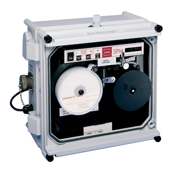
- Page 2 SPM Single Point Monitor 12 13 Single Point Monitor SYSTEM STATUS ALARM RELAY ALARM ALARM DIS- TEST RESET MDA Scientific, Inc. ABLE Line power cord Red Relay disable LED Capstan assembly Power port Relay disable key Guide post 14-pin circular connector...
-
Page 3: Table Of Contents
Single Point Monitor Table of Contents 1 Operation 1.1 Introduction ......................1-2 1.2 Master SPM Illustration ..................1-2 1.3 Before You Begin ....................1-2 1.4 Switching Instrument On and Off ................. 1-2 1.5 Loading the Chemcassette Detection Tape ............1-3 ®... - Page 4 Single Point Monitor 2.3.5 Exhaust Line ....................2-4 2.3.6 High Pressure Locations ................. 2-4 2.4 SPM Output Connections ..................2-4 2.4.1 Output Pin Designations ................. 2-4 2.5 How to Open Instrument Cover ................2-5 3 Maintenance 3.1 Routine Maintenance Schedule ................3-2 3.2 Chemcassette...
- Page 5 5.3.2 Setting the Duty Cycle..................5-7 5.3.3 Duty Cycle Concentration Reporting ............... 5-8 5.4 ChemKey Option ....................5-8 5.4.1 ChemKey Components ................... 5-8 5.4.2 SPM Legend (71) .................... 5-8 5.4.3 Gas Symbol/Name (72)................... 5-8 5.4.4 Alarm Levels (73) .................... 5-8 5.4.5 Family Chemcassettes ®...
- Page 6 Data and Packets .....................A-3 Check-Character (Checksum) ..................A-4 ACK/NAK Handshake ....................A-4 Normal Analysis Messages ..................A-5 Errors and Faults ......................A-5 Responses .......................A-6 A.2 Protocol Packet Definition ..................A-6 A.2.1 Packet Format .....................A-6 A.4 SPM Protocol Command Parameter Format .............A-7 A.5 Glossary ........................A-8 SPM Technical Handbook TOC-4...
- Page 7 Single Point Monitor B Warranty Statement Chemcassette Device Warranty Statement ..............B-2 ® Chemcassette Warranty ....................B-3 ® SPM Technical Handbook TOC-5...
-
Page 8: Operation
SPM Single Point Monitor 1 Operation Midas Technical Handbook... -
Page 9: Introduction
Caution The SPM is very easy to operate and maintain. The SPM can quickly be set up for monitoring, and routine Except for instrument maintenance procedures maintenance requires less than three hours annually. -
Page 10: Loading The Chemcassette Detection Tape
5. Install the take-up reel cover (27). 6. Rotate the assembled take-up reel (27) clockwise to take up any slack. 7. Install the Chemcassette center retaining ® screw. 8. Close the tape load lever (18). The SPM will automatically begin monitoring. SPM Technical Handbook... -
Page 11: Full Alarm Simulation
Above Alarm Level 2 each level of alarm simulation. • Above Full Scale 1.7.5 Alarm Simulation Reporting To begin a full alarm simulation, the SPM needs to be in Green Monitor Mode. Press and hold the alarm reset key (11) System System... -
Page 12: Verifying System Response
The verification routine checks the operating condition re-thread the tape (7). After pressing the alarm of the SPM optical system through use of the optical test reset button, the alarm lamp (16) does not card supplied with the instrument. The instrument must extinguish. -
Page 13: Gas Concentration Conditions
Status Status LED (16) Signal (11). If the fault condition has not been corrected, the LED (9) LED (12) SPM will revert back to the fault reporting status. Sub- Steady Actual alarm Concentration 1.11 Disabling the External Alarm Relay Steady... - Page 14 SPM Single Point Monitor To re-enable the alarm relay contact, press relay disable (14) a second time. The red relay disable LED (13) will turn off to indicate that all the relay contacts are operational. The instrument fault relay will also reset.
-
Page 15: Installation
SPM Single Point Monitor 2 Installation SPM Technical Handbook... -
Page 16: Wall Mounting
SPM Single Point Monitor 2.1 Wall Mounting For proper operation, place the SPM in a stable, level position protected from accidental bumps or jars. Make sure the planned installation conforms to the local wiring or installation regulations. The SPM accessory kit contains a mounting kit Section 5.8... -
Page 17: Connecting Sample And Exhaust Lines
2.3.3 Acid Scrubbing Filters Warning Acid Scrubbing Filters (P/N 710235) are not to be used on sample inlet lines with SPM instruments. On older units without sample fitting retainer ring, a second wrench must be used to hold the base of fitting stationary during loosening and tightening. -
Page 18: Hydrogen Sulfide
** Do not connect analog devices with more than Chemcassette advancement. Additional parts are ® 850 ohm impedance. required. Please contact Honeywell Analytics for application assistance. Note: The mA range is 4-20mA and does not indicate when 2.4 SPM Output Connections the unit is in a Fault condition. -
Page 19: How To Open Instrument Cover
(29) and the collar (30) must be secured by at least three cover screws (20). • To open the hinged collar (30) from the SPM body (31), you must remove the collar fixing screws (22), one at a time. SPM Technical Handbook... -
Page 20: Maintenance
SPM Single Point Monitor 3 Maintenance Midas Technical Handbook... -
Page 21: Routine Maintenance Schedule
SPM Single Point Monitor 3.1 Routine Maintenance Schedule 3. Remove the three screws and six fiber washers securing the PCB. Note location of fiber washers Three items of routine maintenance apply to all for re-assembly. systems: 4. Leave all cables connected except J-11 (4 pin) and J-3 (10 pin) located on top right of •... -
Page 22: Replacing The Fuse
Amines/Ammonia, Ammonia, Chlorine III/Oxidizers, Diisocyanates, Hydrogen Cyanide, Hydrogen Peroxide, SPM operation is protected with a fuse located in a fuse Ozone, Sulfur Dioxide, and Mineral Acids must be stored holder cap (33) at the lower left front panel. The fuse size in a freezer (less than 0°C;... -
Page 23: Removing A Used Chemcassette
SPM Single Point Monitor 3.7 Removing a Used Chemcassette ® The following actions should be taken to isolate the cause of the system malfunction or failure to activate: Warning 1. Check to make sure that the green system status Never reuse or rewind a used Chemcassette ®... -
Page 24: Specifications
SPM Single Point Monitor 4 Specifications Midas Technical Handbook... -
Page 25: General Instrument Specifications
Alarm Settings Standard calibrations are factory set at 1/2 The 4-20 mA output on the SPM is always active during and 1 times TLV of the target gas for all gases monitoring. It is updated at the end of each analysis except Diisocyanates (5 ppb or 20 ppb). -
Page 26: Output Signals
SPM Single Point Monitor 4.4 Output Signals Zero LDL** 14.67 Full Scale Gas Calibration 9.33 mA 4.0 mA 4.56 mA* 20.0 mA Ammonia (NH 0 ppm 2.6 ppm 25.0 ppm 50.0 ppm 75.0 ppm Ammonia XP (NH 0 ppm 1.5 ppm* 25.0 ppm... - Page 27 SPM Single Point Monitor Zero LDL** 14.67 Full Scale Gas Calibration 9.33 mA 4.0 mA 4.56 mA* 20.0 mA Hydrogen Bromide XP (HBr) 0 ppm 0.2 ppm 2.0 ppm 4.0 ppm 6.0 ppm Hydrogen Bromide XP (HBr) Low Level 0 ppb...
- Page 28 SPM Single Point Monitor Zero LDL** 14.67 Full Scale Gas Calibration 9.33 mA 4.0 mA 4.56 mA* 20.0 mA Nitrogen Dioxide (NO ) [on F /Oxidizer CC] 0 ppm 0.3 ppm 3.0 ppm 6.0 ppm 9.0 ppm Ozone (O 0 ppb...
-
Page 29: Status Indicators
Section 3.8 High Background Counts (See No. 3) flash, audio alarm pulses and the instrument fault relay Reference Voltage #1 Fault, Contact Honeywell Analytics is activated. Battery Very Low Response Verification Green system status LED (9) flashing rapidly. If system... -
Page 30: Output Terminal Status
SPM Single Point Monitor 4.8 Output Terminal Status Alarm Relay Terminals Alarm Level Alarm Level *Instrument Fault Condition Power Off Power On, No Gas Power On, Gas (Level 1) Power On, Gas (Level 2) Power On, Fault Power On, Alarm Test... -
Page 31: Gas Response Specifications
SPM Single Point Monitor 4.9 Gas Response Specifications Default Default Sample Chemcassette Part Number ® (Threshold Alarm Alarm Time Gas Name Limit Value) Level 1 Level 2 (sec) Amines 25 ppm 12.5 ppm 25 ppm 706042 700342 1740-9309 Ammonia (NH... - Page 32 SPM Single Point Monitor Default Default Sample Chemcassette Part Number ® (Threshold Alarm Alarm Time Gas Name Limit Value) Level 1 Level 2 (sec) Hydrides (cont’d) Hydrogen Sulfide (H 10 ppm 5.1 ppm 10 ppm 1740-9300 Hydrogen Sulfide (H S) Dry 10 ppm 5.1 ppm...
- Page 33 Sulfur Dioxide (SO 250 ppb 125 ppb 250 ppb 705027 700350 Other alarm levels can be made available - consult Honeywell Analytics Nitrogen Dioxide using Chlorine III Chemcassette ® XPS Chemcassette requires the appropriate calibration Nitrogen Dioxide using Fluorine/Oxidizer Chemcassette ®...
-
Page 34: Sample Line Limitations
SPM Single Point Monitor 4.10 Sample Line Limitations 4.11 Particulate Filters Certain target gases carry sample line restrictions. Note that For dusty conditions, particulate filters may be installed on the limits are maximums; shorter sample lines are acceptable. sample lines for certain gases. For noncorrosive gases, use Sample line material must be 1/8”... - Page 35 Note: When monitoring for gases using low-level calibrations, additional sample line restrictions may apply. Consult Honeywell Analytics. Caution Acid scrubbing filters (P/N 710235) are not to be used with SPM sample lines. Maximum Sample Length RH of (with extended sample...
-
Page 36: Options
SPM Single Point Monitor 5 Options SPM Technical Handbook... -
Page 37: Accupulse Dilution System
SPM Single Point Monitor 5.1 AccuPulse Dilution System 5.2 Z-Purge System Option The SPM fitted with the Z-Purge option is housed in a The heart of the AccuPulse Dilution System is a Teflon rugged, NEMA 4X fiberglass enclosure. [See Z-Purge 3-way solenoid valve with millisecond speed of response. -
Page 38: User Responsibility
53. Purge outlet valve located in a non-hazardous area. The air supply lines 21. Retaining ring 54. Purge pressure gauge from the compressor to the SPM should be made of a 22. Collar fixing screw 55. Override switch non-combustible material. -
Page 39: Electrical Connection
(30) must be secured by at least three cover To Grnd screws (20). Stud • To open the hinged collar (30) from the SPM body (31), you must remove the collar fixing screws (22) one at a time. • Observe that the collar fixing screws (22) are To Grnd mounted behind the cover screws (20). -
Page 40: Output Connections
Terminal strip (61) for gas alarms relays, instrument fault relay, and 4-20 mA output. All wiring entering and exiting the SPM enclosure must be properly seal fitted, dammed, and potted before the instrument is put into service. After making the... -
Page 41: Z-Purge Servicing And Power-Up Procedures
Do not restore power unless area is known to be non-hazardous or unless power has been removed The Model SPM Gas Monitor with Z-Purge requires from all devices within the enclosure for five that certain procedures be followed when servicing the minutes. -
Page 42: Z-Purge Troubleshooting
If the Duty Cycle period is set to less than 1-1/2 minutes, to activate the pressure switch. the SPM will continue to draw a sample. If the Duty Cycle is set to 1-1/2 minutes or greater, then the SPM will shut... -
Page 43: Duty Cycle Concentration Reporting
6. Close the tape load lever (18) to return to monitor other Honeywell Analytics systems. Make sure that mode. the ChemKey you use on an SPM unit carries an SPM 5.3.3 Duty Cycle Concentration Reporting designation. In between sample periods, the digital display (19) 5.4.3 Gas Symbol/Name (72) -
Page 44: Sample Lines
(8). At If after checking the ChemKey position and determining start-up, the SPM display will show the name of the that it is properly inserted, turned on, and labeled SPM, gas, programmed alarm levels, and the appropriate... -
Page 45: Pin Designations
Standard SPM Z-Purge SPM Ground The chart and illustrations show SPM pin designations for both standard SPM units and for Z-Purge units. For Transmit + Z-Purge systems, the numbered connectors are directly Transmit – matched. Both portions of the connector are provided. -
Page 46: Portable Operation
When not will not activate. The relays will also be in use as a portable monitor, the Portable SPM should disabled if the SPM enters a fault condition or be connected to AC power source via its battery charger if power is turned off or lost. -
Page 47: Extended Sample Option
To release the tubing, push the small gray collar in while pulling the tubing out. 5.8 Pole Mount Kit 5.7.2 Connecting the Sample Line The Pole Mount Kit option allows the SPM to be securely SPM Technical Handbook 5-12... -
Page 48: Heater Option
The Power In LED (80) does not indicate that the SPM is monitoring. The main power switch (8) must be on to activate the SPM for monitoring which will be indicated by the green system 21 mm status LED (9). -
Page 49: Condensation
81. Heater On LED The SPM will not power up or monitor until the internal If the SPM is disconnected from an AC source for more temperature falls below +40°C (+104°F). All relay outputs than 30 minutes, the SPM must be allowed to warm up and alarms will revert to the power off condition. -
Page 50: Two-Point Operation
SPM. An SPM installed with this option will not be able to signal the specific point at which a release The operation of the 2-point SPM is the same as a basic has occurred, but will indicate that one of the monitoring SPM with the exception of longer sample lines and a points is in a gas condition. -
Page 51: Non-Latching Alarm Option
SPM pauses to await another trigger. When of tape in the optics even when no tape is present. Since a trigger is sent, the SPM sets the 4-20 mA output to 4 there is no end-of-tape fault, you must be aware of the mA, and shows (SAMPLING) on the display. - Page 52 Visual observation of the Chemcassette supply is required. If high humidities are causing false ppb readings with your SPM monitor, contact Honeywell Analytics’ Service Department to arrange for the optics modification to be installed. Request P/N 870708 for the SPM.
-
Page 53: A Bi-Directional Communications Protocol
SPM Single Point Monitor A Bi-Directional Communications Protocol SPM Technical Handbook... -
Page 54: Introduction
SPM The SPM uses 8 bits per character, with one (1) stop operation from another location. It will also allow you to bit and NO parity. -
Page 55: Communication Port Timeout
SPM for each communication that occurs. The collection of the above three bytes (which made After each query, the SPM waits for one second for the our message) may be referred to as a packet, as these response. -
Page 56: Check-Character (Checksum
ACKnowledge. Your equipment sends it back to tell the SPM that the packet is ok. If, however, the The SPM’s data within the packet is interpreted in a check-character did not match, you may elect to send somewhat different manner than the above example. -
Page 57: Normal Analysis Messages
SPM Single Point Monitor Normal Analysis Messages Table A-4 is a list of valid commands that the SPM will issue. All command codes in the following table are In MONITOR Mode, the SPM will send gas concentration hexadecimal. The length of each parameter is indicated. -
Page 58: Responses
Check-character. This byte is the last character in the packet. Its value is equal to the negated summation of all previous bytes The SPM re-sends the last packet if it receives an NAK in the packet. It is the negative checksum of the packet. -
Page 59: Spm Protocol Command Parameter Format
Date Year is based from 1980; 1989 would be 89 – 80 = 9; 9 = 0 0 0 1 0 0 1 A number indicating a specific type of fault. Consult SPM manual for fault Fault Number codes. Top bit indicates ppm or ppb (1= ppm). The remaining 7 bits indicate decimal Format Code position. -
Page 60: Glossary
SPM PROTOCOL refers to the PACKET of BYTES the SPM recognizes. TIME-OUT: refers to the maximum amount of time that SPM instrument allows for the equipment to respond to a packet sent from the instrument. If the time period is exceeded, then the SPM will ignore any additional responses to it. - Page 61 SPM Single Point Monitor B Warranty Statement SPM Technical Handbook...
- Page 62 Service Contracts. Analytics under a Quality Management System that is certified to ISO 9001. Honeywell Analytics shall not be liable for any loss or As such, this instrument (including the pump) is damage whatsoever or howsoever occasioned which...
- Page 63 SPM Single Point Monitor in Honeywell Analytics’ instruments. Honeywell Analytics reserves the right to change this policy at any time. Contact Honeywell Analytics for the most current warranty information. Chemcassette Warranty ® All Chemcassettes are warranted for a period not to ®...
- Page 64 Thank you for reading this data sheet. For pricing or for further information, please contact us at our UK Office, using the details below. UK Office Keison Products, P.O. Box 2124, Chelmsford, Essex, CM1 3UP, England. Tel: +44 (0)1245 600560 Fax: +44 (0)1245 808399 Email: sales@keison.co.uk...