Advertisement
Quick Links
T
ECHNICAL INFORMATION
Models No.
Description
C
ONCEPTION AND MAIN APPLICATIONS
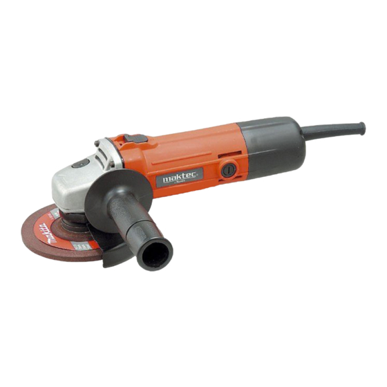
New power tool series from MAKITA.
115mm (4-1/2") and 125mm (5'') angle grinders have
been added to MAKTEC series tools.
* Conveniently located slide switch
* Less expensive but service life is as long as existing
MAKITA models.
* Easy-to-repair construction
S
pecification
Voltage (V)
110
120
220
230
240
Wheel size
: mm ( " )
No load speed : min.
Protection from electric shock
Cord length : m ( ft )
Net weight : kg ( lbs )
S
tandard equipment
* Lock nut wrench ................................. 1 pc.
* Grip 36 complete ................................ 1 pc.
< Note > The standard equipment for the tool shown may differ from country to country.
MT952 / MT953
Angle Grinders 115mm (4-1/2") / 125m (5")
Current (A)
Cycle (Hz)
5.5
50 / 60
5.0
50 / 60
2.7
50 / 60
50 / 60
2.5
50 / 60
2.6
Diameter
115 ( 4-1/2 )
Hole diameter
Thickness
-1 = rpm.
H
W
Model No.
Length ( L )
Width ( W )
Height ( H )
Continuous Rating (W)
Input
570
570
570
570
MT952
MT953
125 ( 5 )
22.23 ( 7/8 )
6 ( 1/4 )
10,000
by double insulation
2.0 ( 6.6 )
1.5 ( 3.3 )
PRODUCT
L
Dimensions : mm ( " )
MT952
MT953
266 (10-1/2)
266 (10-1/2)
129 (5-1/8)
139 (5-1/2)
103 (4-1/16)
103 (4-1/16)
Max. Output(W)
Output
350
650
350
650
350
650
350
650
350
650
P 1 / 7
Advertisement

Summary of Contents for Makita MT952
- Page 1 MT952 / MT953 Description Angle Grinders 115mm (4-1/2") / 125m (5") ONCEPTION AND MAIN APPLICATIONS New power tool series from MAKITA. 115mm (4-1/2") and 125mm (5'') angle grinders have been added to MAKTEC series tools. * Conveniently located slide switch * Less expensive but service life is as long as existing MAKITA models.
- Page 2 P 2 / 7 epair < 1 > Lubrication Apply MAKITA grease N. No.1 to the following portions marked with black triangle to protect parts and product from unusual abrasion. Spiral bevel gear 11 Teeth portion Gear housing Put 10g into gear room...
- Page 3 P 3 / 7 epair < 3 > Assembling armature section (including spiral bevel gear 11) ( 1 ) Pass bearing retainer through the armature shaft. See Fig. 5. ( 2 ) Put flat washer 10 on ball bearing 6000ZZ which has been set on the bearing setting plate. And press armature with arbor press to mount ball bearing 6000ZZ to armature.
- Page 4 P 4 / 7 epair ( 4 ) Remove retaining ring R- 32. And then, remove ball bearing 6201DDW with arbor press as illustrated in Fig. 11. Round bar for arbor Bearing box Bearing box Flat washer 12 Retaining Ball bearing 6201DDW ring R- 32 Fig.
- Page 5 P 5 / 7 ircuit diagram Color index of lead wires Black White Noise suppressor Switch Terminal block Field < Note > The products for some country are not equipped with noise suppressor. iring diagram Wiring in motor housing Connect to switch Field lead wire (white) Field lead wire (black) Connect to terminal block...
-
Page 6: Bottom View
P 6 / 7 iring diagram Wiring on switch box Bottom view Fix the following lead wires with these lead holders. * Noise suppressor's lead wire to be connected with terminal block * Field's lead wire (black) to be connected with terminal block Terminal Bottom view block... -
Page 7: Left View
P 7 / 7 iring diagram Wiring on switch box Top view 1 Top view 2 Top view 1 Top view 2 Do not slack field lead wire (white) in this area. Put noise suppressor in this space Under the noise suppressor, put field lead wire (white) in the groove as illustrated in Fig.


