HIKVISION DS-KD3002-VM User Manual
Residential video intercom bundle
Hide thumbs
Also See for DS-KD3002-VM:
- Quick start manual (27 pages) ,
- User manual (114 pages) ,
- User manual (104 pages)
Table of Contents
Advertisement
Quick Links
Advertisement
Table of Contents

Related Manuals for HIKVISION DS-KD3002-VM


Summary of Contents for HIKVISION DS-KD3002-VM
- Page 1 Residential Video Intercom Bundle User Manual...
- Page 2 Trademarks and other Hikvision marks are the property of Hikvision and are registered trademarks or the subject of applications for the same by Hikvision and/or its affiliates. Other trademarks mentioned in this manual are the properties of their respective owners. No right of license is given to use such trademarks without express permission.
- Page 3 Residential Video Intercom Bundle·User Manual Regulatory Information FCC Information Please take attention that changes or modification not expressly approved by the party responsible for compliance could void the user’s authority to operate the equipment. FCC compliance: This equipment has been tested and found to comply with the limits for a Class A digital device, pursuant to part 15 of the FCC Rules.
- Page 4 Residential Video Intercom Bundle·User Manual Safety Instruction These instructions are intended to ensure that user can use the product correctly to avoid danger or property loss. The precaution measure is divided into Warnings and Cautions: Warnings: Neglecting any of the warnings may cause serious injury or death. Cautions: Neglecting any of the cautions may cause injury or equipment damage.
- Page 5 Residential Video Intercom Bundle·User Manual Do not place the device in extremely hot (refer to the specification of the device for the detailed operating temperature), cold, dusty or damp locations, and do not expose it to high electromagnetic radiation. ...
-
Page 6: Table Of Contents
Residential Video Intercom Bundle·User Manual Table of Contents 1 Introduction ....................1 1.1 Overview ........................1 1.2 Typical Application ....................1 1.3 Bundle Wiring ......................2 2 Appearance Description ................4 2.1 Indoor Station ......................4 2.1.1 Front Panel ......................4 2.1.2 Rear Panel ...................... - Page 7 Residential Video Intercom Bundle·User Manual 6.1 Getting Started ...................... 30 6.2 Initiate Video Intercom ..................30 6.3 Unlock the Door ..................... 30 Appendix ...................... 31 Video/Audio Distributor Power Supply ............... 31 Door Station Power Supply ..................33...
-
Page 8: Introduction
Residential Video Intercom Bundle·User Manual 1 Introduction 1.1 Overview The residential video intercom bundle is composed of and an indoor station, a door station and a video/audio distributor. Featuring in the convenient installation and easy operation, it is meanly applied in the buildings for improving the living security. 1.2 Typical Application Figure 1-1 Typical Application ... -
Page 9: Bundle Wiring
1.3 Bundle Wiring Figure 1-2 Bundle Wiring See the appendix for the power supply connection of door station and video/audio distributor. Connect LAN2 of door station to the bus input on the video/audio distributor via network cable. Before configure the device, set Digit 8 (RW1) as ON to adapt to the current indoor station version. -
Page 11: Appearance Description
3 Appearance Description 3.1 Indoor Station 3.1.1 Front Panel Figure 3-1 Front Panel Table 3-1 Components Description Description Volume Wheel Power Supply Indicator Alarm Indicator Answer/Decline Key Unlock Key Live View Key Management Center Key LCD Display Screen Microphone Arm/Disarm Key The Unlock key is valid only when does the indoor station speak with the door station or open the live view of the door station. -
Page 12: Rear Panel
3.1.2 Rear Panel Figure 3-2 Rear Panel Table 3-2 Components Description Description Network Interface(24 VDC) Reserved Loudspeaker Terminals... -
Page 13: Door Station
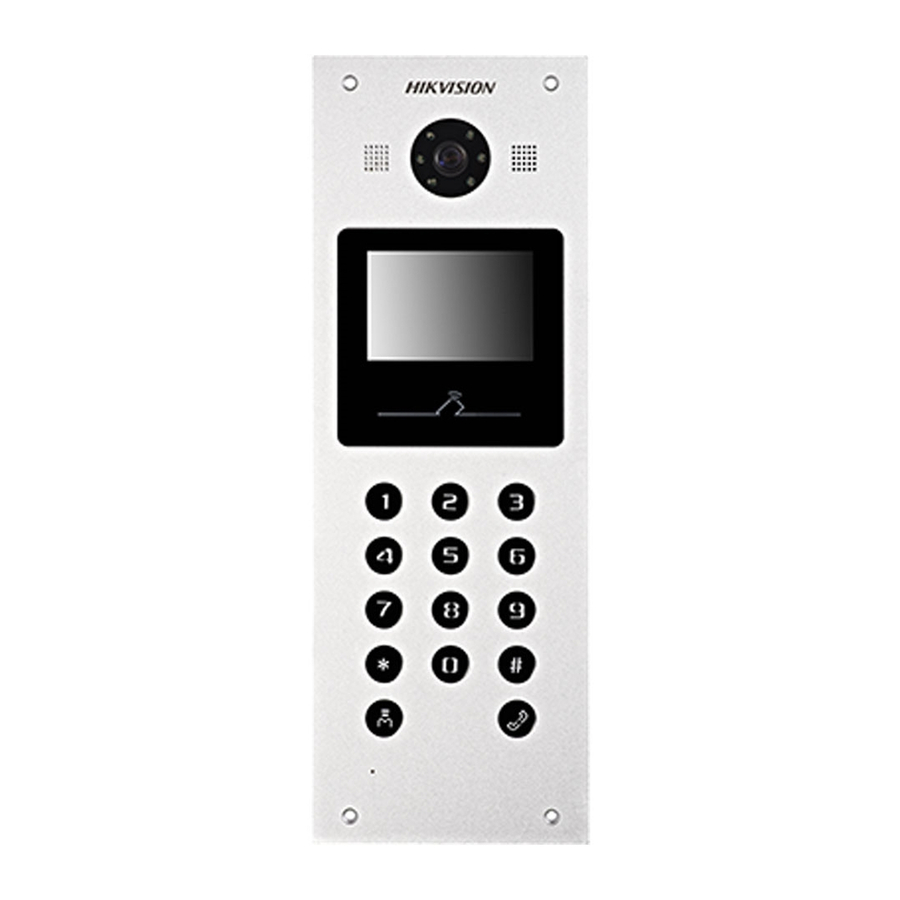
3.2 Door Station Figure 3-3 Front View Figure 3-4 Rear View Table 3-3 Components Description Description Low Illumination Supplement Light Built-in Camera Loudspeaker LCD Display Screen Card Induction Area Keypad Call Button Call Center Key Microphone... -
Page 14: Video/Audio Distributor
Description TAMPER 3.3 Video/Audio Distributor 3.3.1 Front Panel/Back Panel Figure 3-6 Back Panel Figure 3-5 Front Panel Table 3-4 Components Description Description Signal Indicator Power Indicator... -
Page 15: Side Panel
3.3.2 Side Panel Figure 3-7 DS-KAD312 Side Panel 1 Figure 3-8 DS-KAD312 Side Panel 2 Figure 3-9 DS-KAD312 Side Panel 3 Table 3-5 Components Description Description Power Socket... - Page 16 Network Interface DIP Switch Serial Port...
-
Page 17: Terminals And Wirings
4 Terminals and Wirings 4.1 Terminals 4.1.1 Indoor Station Terminals Figure 4-1 Terminals of DS-KH3200-L Table 4-1 Descriptions of Terminals and Interfaces Description Grounding Zone Detector Input Terminal 1(Smoke Detector) Zone Detector Input Terminal 2(Gas Detector) Zone Detector Input Terminal 3(Door Magnetic) Zone Detector Input Terminal 4(Active Infrared) Grounding... -
Page 18: Door Station Terminals
4.1.2 Door Station Terminals Figure 4-2 Terminals and Interfaces of DS-KD3002-VM Table 4-2 Descriptions of Terminals and Interfaces Name Interface Description USB Interface LAN1 Network Interface LAN2 Analog Interface Power DC 12V DC 12V Power Supply Input Supply Power Supply Output... -
Page 19: Video/Audio Distributor Interfaces
Name Interface Description AO2+ AO1- Alarm Relay Output 1 AO1+ Grounding Serial Port Debugging/Receive data DEBUG Serial Port Debugging/Send data 3.3V Serial Port Debugging/Power Supply Power Supply Output Grounding Door Lock Relay Output (NC) COM2 Grounding Signal DOOR Door Lock Relay Output (NO) Door Lock Relay Output (NC) COM1 Grounding Signal... -
Page 20: Wirings
Figure 4-3 Network Interfaces of DS-KAD312 Table 4-3 Descriptions of Interfaces Description Description Decoding Output Interface 1 Decoding Output Interface 8 Decoding Output Interface 2 Decoding Output Interface 9 Decoding Output Interface 3 Decoding Output Interface 10 Decoding Output Interface 4 Decoding Output Interface 11 Decoding Output Interface 5 Decoding Output Interface 12... -
Page 21: Door Station Wiring
Figure 4-4 Wiring Description (Alarm Input Device) The accessed detector should be normally closed. 4.2.2 Door Station Wiring Door Lock Wiring Figure 4-5 Door Lock Wiring... -
Page 22: Door Magnetic Wiring
Terminal NC1/COM1 is set as default for accessing magnetic lock/electric bolt; terminal NO1/COM1 is set as default for accessing electric strike. To connect electric lock in terminal NO2/COM2/NC2, it is required to set the output of terminal NO2/COM2/NC2 to be electric lock with Batch Configuration Tool or iVMS-4200. -
Page 23: Exit Button Wiring
Exit Button Wiring Figure 4-7 Exit Button Wiring Terminal S1 is set as default for connecting exit button. External Card Reader Wiring Please set the DIP switch first before connecting the card reader. If the DIP switch should be configured when the card reader is power-on, please reboot the card reader after configuring the DIP switch. - Page 24 Figure 4-8 RS-485 Card Reader Wiring Wiegand Card Reader Wiring Figure 4-9 External Card Reader Wiring...
-
Page 25: Alarm Device Input Wiring
Alarm Device Input Wiring Figure 4-10 Alarm Device Input Wiring Alarm Device Output Wiring Figure 4-11 Alarm Device Output Wiring... -
Page 26: Dip Settings
5 DIP Settings Figure 5-1 DIP Switches of DS-KAD312 Table 5-1 Descriptions of RW1 and RW2 Digit (RW1) Function Floors Floors Reserved Room Room Room Reserved Mode (RW1) Digit (RW2) Function Floors Floors Floors Floors Floors Floors Floors Floors (RW2) ... - Page 27 Digit Floor No. (RW1) 1 floor with 12 households 2 floors with 6 households each 3 floors with 4 Status households each 4 floors with 3 households each 6 floors with 2 households each * means irrelevant, ON means 1, OFF means 0. ...
- Page 28 Digit Floor No. (RW1) 4 floors with 3 households each 6 floors with 2 households each * means irrelevant, ON means 1, OFF means 0. Digit 1 and Digit 2 (RW1) are set as OFF by default, means 1 floor with 12 households. ...
-
Page 29: Configure Rw 2
Digit Room No. of (RW1) * means irrelevant, ON means 1, OFF means 0. Digit 4, Digit5 and Digit 6 (RW1) are set as OFF by default. When Digit4 and Digit5 are set as OFF, it means 1 floor with 12 households. For example, if you set the device as the table below, then the Room No. - Page 30 For example, if you set Digit1, Digit2 and Digit4 to be ON (as the table below), then the start floor No. is 11. That is, 1+2+8=11. Table 5-7 RW2 Configuration Example of DS-KAD312 Digit (RW2) Binary Value Status...
-
Page 31: Installation
6 Installation 6.1 Indoor Station Installation 6.1.1 Installation Accessory Description The wall mounting plate and the junction box are required to install the indoor station onto the wall. The dimension of junction box should be 75 mm (width) × 75 mm (length) × 50 mm (depth). - Page 32 1. Chisel a hole in the wall. The size of the hole should be 76 mm (width) × 76 mm (length) × 50 mm (depth). 2. Insert the junction box to the hole chiseled on the wall. 3. Fix the wall mounting plate to the junction box with 2 screws. Wall Mounting Plate Screws...
-
Page 33: Door Station Installation
6.2.1 Installation Accessory Description Figure 6-4 Front and Side View The dimension of gang box for model DS-KD3002-VM door station is: 343(length)× 113(width)×55(depth) mm. The dimensions above are for reference only. The actual size can be slightly different from the theoretical dimension. - Page 34 Screw Screw Figure 6-5 Insert the Gang Box into the Wall 3. Make sure the edges of the gang box align to the wall. 4. Route the cables of the door station through the cable hole. 5. Put the door station into the gang box. Figure 6-6 Install the Door Station 6.
-
Page 35: Video/Audio Distributor Installation
Figure 6-7 Tighten the Screws of Device 6.3 Video/Audio Distributor Installation Video/audio distributor can be set on a desk and also support wall mounting. The wall mounting steps as below: Steps: 1. Chisel two holes in the wall. The diameter of the hole is 3 mm, and the distance between two holes is 136 mm. - Page 36 Figure 6-9 Wall Mounting-2...
-
Page 37: Local Operation
7 Local Operation 7.1 Getting Started Before you start: Make sure all devices in the bundle have been well connected. The power supply the indoor station supports is 24 VDC. Please make sure your power supply matches your indoor station. Steps: Power on the indoor station, door station. -
Page 38: Appendix
Appendix Video/Audio Distributor Power Supply It needs two parts to power the video/audio distributor: power cable and power box, as below. Figure 7-1 Power Cable Figure 7-2 Power Box To power the video/audio distributor, you need to connect the cable and power box as below: Steps: 1. - Page 39 Figure 7-3 Cut and Peal the Cable The three lines’ description: Color Description Yellow-green Grounding Line Brown Fire Line Blue Zero Line 2. Peal the three lines to expose the metal wire and connect to the terminal of the power box accordingly.
-
Page 40: Door Station Power Supply
Figure 7-4 Connect to the Power Box Power box terminal description: Terminal Description L(+) Fire Line N(-) Zero Line Grounding Line Negative Pole Positive Pole 3. Connect the negative pole and positive pole to the video/audio distributor accordingly. Door Station Power Supply The power adapter for door station as below. - Page 41 Figure 7-5 Power Adapter To power the door station, you need to deal with the adapter as below: Steps: 1. Cut and peal the cable to exposure the metal wire as below. Figure 7-6 Cut and Peal the Cable...
- Page 42 2. Plug the wire in to the block, and fixed. Figure 7-7 Connect to the Power Box 3. Connect the block to the door station’s power supply input terminal accordingly.
- Page 43 UD09863B...