
Related Manuals for Cisco Aironet 1800s


Summary of Contents for Cisco Aironet 1800s
- Page 1 ETTING TARTED UIDE Cisco Aironet 1800s Network Sensor First Published: April 5, 2017...
- Page 2 About this Guide About the Network Sensor Safety Instructions Unpacking the 1800s Network Sensor Ports and Connectors on the 1800s Preparing the AP for Installation Installation Overview Performing a Pre-Installation Configuration Mounting and Powering the Network Sensor Configuring the Network Sensor for Wireless Service Assurance Configuring the Network Sensor for Wireless Service Assurance Checking the Network Sensor LED Miscellaneous Usage and Configuration Guidelines...
-
Page 3: About This Guide
This guide provides instructions on how to install and configure your Cisco Aironet 1800s Network Sensor. This guide also provides mounting instructions and limited troubleshooting procedures. The Cisco Aironet 1800s Network Sensor is referred to as the network sensor, or sensor in this document. -
Page 4: Network Sensor Features
Network Sensor Features A full listing of the network sensor's features and specification are provided in the Cisco Aironet 1800s Network Sensor Data Sheet, at the following URL: (URL to be added at CCO) The features of the 1800s network sensors are as follows: •... - Page 5 • One multi-color LED status indicator. See the “Checking the Network Sensor LED” section on page 18 for information on the colors of the LED status indicator. BLE atnenna gain is 1 dBi...
-
Page 6: Safety Instructions
Translated versions of the following safety warnings are provided in the translated safety warnings document that is shipped with your network sensor. The translated warnings are also in the Translated Safety Warnings for Cisco Aironet Network Sensors, which is available on Cisco.com. Warning IMPORTANT SAFETY INSTRUCTIONS... - Page 7 Return any packing material to the shipping container and save it for future use. Step 3 Verify that you have received the items listed below. If any item is missing or damaged, contact your Cisco representative or reseller for instructions. The network sensor base unit. –...
- Page 8 Ports and Connectors on the 1800s Figure 1 Status LED and Ports Location – Face of the Sensor Reset button, on the right side of the sensor. For information on how to use the Reset button, see “Using the Reset Button” section on page Status LED.
-
Page 9: Installation Overview
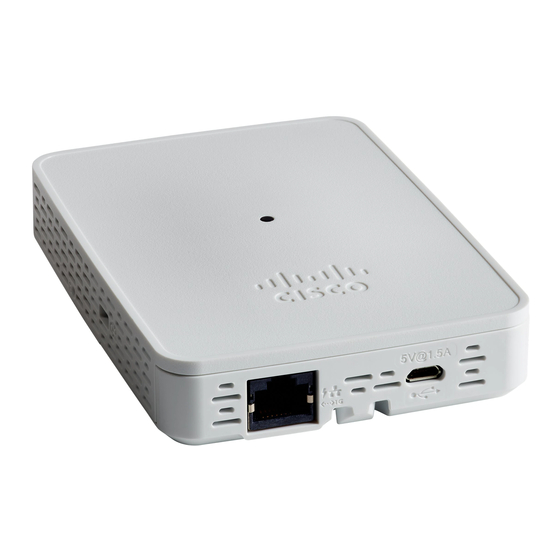
Figure 2 Base of the Network Sensor – With AIR-MOD-POE-xx PoE/Ethernet Module 10/100/1000 BASE-T (Ethernet) Uplink USB port for powering the sensor, using 5V, Interface with inline power capability, 1.5A power. Auto-MDIX (automatically support either straight through or crossover cables), and 802.3af/at PoE-In Installation Overview Installing the network sensor involves these operations:... - Page 10 Mounting and Powering the Network Sensor Cisco Aironet 1800s series network sensors can be mounted in a vertical orientation, on a wall or desk. You can also mount the sensor on an electrical or network box. The mounting and powering options are provided in the following table.
-
Page 11: Mounting The Sensor Using Air-Ap-Bracket-Ns
Mounting the Sensor using AIR-AP-BRACKET-NS The Cisco Aironet 1800s wireless sensor can be mounted, in a vertical orientation, on a wall or desk, to a height of 3 feet, using the wall-mount bracket AIR-AP-BRACKET-NS. To mount the sensor, follow these instructions: Step 1 Identify the location for mounting the sensor. - Page 12 Figure 3 Wall and Desk Mounting Bracket AIR-AP-BRACKET-NS Screw holes for fastening the bracket to the Hooks which click into the recesses on the wall or desk. back the sensor, for mounting the sensor on the bracket.
- Page 13 Figure 4 Back of the Sensor – With PoE/Ethernet Module AIR-MOD-POE-xx Recesses on the back of the sensor into which RS-232 console interface port, hidden under the hooks on the wall-mount bracket slide a mylar label. You need to use the custom and click into place.
- Page 14 Figure 5 Back of the Sensor – With USB adapter module AIR-MOD-USB-xx Recesses on the back of the sensor into which RS-232 console interface port, hidden under the hooks on the wall-mount bracket slide a mylar label. You need to use the custom and click into place.
-
Page 15: Mounting The Sensor Using Air-Mod-Ac-Xx Cradle
Mounting the Sensor using AIR-MOD-AC-xx Cradle The AIR-MOD-AC-xx AC adapter module also functions as a mounting cradle, using which you can plug-in (and thereby, mount) the sensor into a wall socket power outlet. You can additionally secure the sensor by fasting the security wire to the wall or desk. Figure 6 Back of the Sensor –... - Page 16 AC Cradle Options for Different Power Supply Standards and Regions Figure 7 Sensor with AC Cradle for AU Region...
- Page 17 Figure 8 Sensor with AC Cradle for CN Region...
- Page 18 Figure 9 Sensor with AC Cradle for EU Region...
- Page 19 Figure 10 Sensor with AC Cradle for SA Region...
- Page 20 Figure 11 Sensor with AC Cradle for UK Region...
- Page 21 Figure 12 Sensor with AC Cradle for US Region...
- Page 22 • Collect stats and data from Network Sensors, Infrastructure APs and Clients and display real time information from the data collected. • Interfaces with Cisco Cloud Service to send the collected data at regular intervals, to enable the cloud service to display historical information about the wireless network health.
-
Page 23: Network Sensor Status Led
Troubleshooting and Resetting the Network Sensor Network Sensor Status LED Note It is expected that there will be small variations in the LED color intensity and hue from unit to unit. This is within the normal range of the LED manufacturer’s specifications and is not a defect. -
Page 24: Ethernet Port Leds
One of the following: • Environment variable failure • Bad MAC address • Ethernet failure during image recovery • Boot environment failure • No Cisco image file • Boot failure Cisco Network Sensor Software failure; try disconnecting and Operating System... -
Page 25: Using The Reset Button
If you keep the Reset button pressed for more than 60 seconds, the Reset button is assumed faulty and no changes are made. Related Documentation All user documentation for the Cisco Aironet 1800s series network sensor is available at the following URL: (To be added at CCO/FCS) -
Page 26: Declarations Of Conformity And Regulatory Information
Declarations of Conformity and Regulatory Information This section provides declarations of conformity and regulatory information for the Cisco Aironet 1800s Network Sensor. You can find additional information at this URL: www.cisco.com/go/aironet/compliance Manufacturers Federal Communication Commission Declaration of Conformity Statement Tested To Comply... -
Page 27: Vcci Statement For Japan
The Part 15 radio device operates on a non-interference basis with other devices operating Caution at this frequency when using the integrated antennas. Any changes or modification to the product not expressly approved by Cisco could void the user’s authority to operate this device. VCCI Statement for Japan... -
Page 28: Guidelines For Operating Cisco Aironet Network Sensors In Japan
Guidelines for Operating Cisco Aironet Network Sensors in Japan This section provides guidelines for avoiding interference when operating Cisco Aironet network sensors in Japan. These guidelines are provided in both Japanese and English. Japanese Translation 03-6434-6500 English Translation This equipment operates in the same frequency bandwidth as industrial, scientific, and medical devices such as microwave ovens and mobile object identification (RF-ID) systems (licensed premises radio stations and unlicensed specified low-power radio stations) used in factory production lines. - Page 29 Material Safety Law prohibits the use of UL-certified cables (that have the “UL” shown on the code) for any other electrical devices than products designated by CISCO. The use of cables that are certified by Electrical Appliance and Material Safety Law (that have “PSE” shown on the code) is not limited...
-
Page 30: Industry Canada
Industry Canada Network Sensor Models Certification Number AIR-AP1800S-A-K9 2461B-102108 Canadian Compliance Statement This device complies with Industry Canada licence-exempt RSS standard(s). Operation is subject to the following two conditions: (1) this device may not cause interference, and (2) this device must accept any interference, including interference that may cause undesired operation of the device.... -
Page 31: European Community, Switzerland, Norway, Iceland, And Liechtenstein
Antenna Type Antenna Gain Antenna Impedance 3/5 dBi Dual-band Omni 50 ohms Operation in the band 5150-5250 MHz is only for indoor use to reduce the potential for harmful interference to co-channel mobile satellite systems. La bande 5 150-5 250 MHz est réservés uniquement pour une utilisation à l'intérieur afin de réduire les risques de brouillage préjudiciable aux systèmes de satellites mobiles utilisant les mêmes canaux. - Page 32 Declaration of Conformity with regard to the R&TTE Directive 1999/5/EC & Medical Directive 93/42/EEC...
- Page 33 The following standards were applied: EMC—EN 301.489-1 v1.9.2; EN 301.489-17 v2.2.1 Health & Safety—EN60950-1: 2006; EN 50385: 2002 Radio—EN 300 328 v 1.8.1; EN 301.893 v 1.7.1 The conformity assessment procedure referred to in Article 10.4 and Annex III of Directive 1999/5/EC has been followed.
-
Page 34: Declaration Of Conformity For Rf Exposure
This section contains information on compliance with guidelines related to RF exposure. Generic Discussion on RF Exposure The Cisco products are designed to comply with the following national and international standards on Human Exposure to Radio Frequencies: • US 47 Code of Federal Regulations Part 2 Subpart J •... -
Page 35: This Device Meets Fcc Guidelines For Exposure To Radio Waves
As such the systems are designed to be operated as to avoid contact with the antennas by the end user. It is recommended to set the system in a location where the antennas can remain at least a minimum distance as specified from the user in accordance to the regulatory guidelines which are designed to reduce the overall exposure of the user or operator. - Page 36 This Device Meets the Industry Canada Guidelines for Exposure to Radio Waves The 1800s network sensor device includes a radio transmitter and receiver. It is designed not to exceed the limits for exposure to radio waves (radio frequency electromagnetic fields) as referenced in Health Canada Safety Code 6.
-
Page 37: Additional Information On Rf Exposure
Additional Information on RF Exposure You can find additional information on the subject at the following links: • Cisco Systems Spread Spectrum Radios and RF Safety white paper at this URL: http://www.cisco.com/warp/public/cc/pd/witc/ao340ap/prodlit/rfhr_wi.htm • FCC Bulletin 56: Questions and Answers about Biological Effects and Potential Hazards of Radio Frequency Electromagnetic Fields •... -
Page 38: Chinese Translation
Chinese Translation... - Page 39 English Translation Administrative Rules for Low-power Radio-Frequency Devices Article 12 For those low-power radio-frequency devices that have already received a type-approval, companies, business units or users should not change its frequencies, increase its power or change its original features and functions. Article 14 The operation of the low-power radio-frequency devices is subject to the conditions that no harmful interference is caused to aviation safety and authorized radio station;...
-
Page 40: Operation Of Cisco Aironet Network Sensors In Brazil
Operation of Cisco Aironet Network Sensors in Brazil This section contains special information for operation of Cisco Aironet network sensors in Brazil. Network Sensor Models: AIR-AP1800S-Z-K9... -
Page 41: Portuguese Translation
© 2017 Cisco Systems, Inc. All rights reserved. Cisco and the Cisco logo are trademarks or registered trademarks of Cisco and/or its affiliates in the U.S. and other countries. To view a list of Cisco trademarks, go to this URL: www.cisco.com/go/trademarks. Third-party trademarks mentioned are the property of their respective owners. The use of the word partner does...