Table of Contents
Advertisement
Cisco UCS 6200 Series Fabric Interconnect Hardware Installation Guide
First Published: 2012-07-19
Last Modified: 2018-03-06
Americas Headquarters
Cisco Systems, Inc.
170 West Tasman Drive
San Jose, CA 95134-1706
USA
http://www.cisco.com
Tel: 408 526-4000
800 553-NETS (6387)
Fax: 408 527-0883
Text Part Number: OL-24475-03
Advertisement
Table of Contents

Related Manuals for Cisco UCS 6248 UP


Summary of Contents for Cisco UCS 6248 UP
- Page 1 Cisco UCS 6200 Series Fabric Interconnect Hardware Installation Guide First Published: 2012-07-19 Last Modified: 2018-03-06 Americas Headquarters Cisco Systems, Inc. 170 West Tasman Drive San Jose, CA 95134-1706 http://www.cisco.com Tel: 408 526-4000 800 553-NETS (6387) Fax: 408 527-0883 Text Part Number: OL-24475-03...
- Page 2 Cisco and the Cisco logo are trademarks or registered trademarks of Cisco and/or its affiliates in the U.S. and other countries. To view a list of Cisco trademarks, go to this URL: https://www.cisco.com/go/trademarks. Third-party trademarks mentioned are the property of their respective owners. The use of the word partner does not imply a partnership relationship between Cisco and any other company.
-
Page 3: Table Of Contents
SFP+ Transceivers SFP Transceivers SFP+ Copper Cables SFP Fibre Channel Transceivers C H A P T E R 2 Installing the Cisco UCS 6200 Series Fabric Interconnect Preparing for Installation Cisco UCS 6200 Series Fabric Interconnect Hardware Installation Guide OL-24475-03... - Page 4 Cable Management Guidelines Required Equipment Unpacking and Inspecting the Cisco UCS 6200 Series Fabric Interconnect Installing the Cisco UCS 6248 UP Chassis in a Cabinet or Rack Grounding the System Installing the Cisco UCS 6296 Chassis in a Cabinet or Rack...
- Page 5 Removing a Cisco UCS 6248 UP Removing a Cisco UCS 6296 Replacing a Fabric Interconnect Upgrading from a Cisco UCS 6248 UP Fabric Interconnect to a Cisco UCS 6296 UP Fabric Interconnect Repacking the Cisco UCS Fabric Interconnect for Return Shipment...
- Page 6 A P P E N D I X D Troubleshooting Hardware Components Overview SNMP Traps Server Port Link State Transitions System Hardware Best Practices Installation Best Practices Initialization Best Practices System Operation Best Practices Cisco UCS 6200 Series Fabric Interconnect Hardware Installation Guide OL-24475-03...
-
Page 7: Preface
Terminal sessions and information that the system displays appear in this font. CLI commands CLI command keywords appear in this font. Variables in a CLI command appear in this font. Elements in square brackets are optional. Cisco UCS 6200 Series Fabric Interconnect Hardware Installation Guide OL-24475-03... - Page 8 Use the statement number provided at the end of each warning to locate its translation in the translated safety warnings that accompanied this device. SAVE THESE INSTRUCTIONS Cisco UCS 6200 Series Fabric Interconnect Hardware Installation Guide viii OL-24475-03...
-
Page 9: Related Cisco Ucs Documentation
Related Cisco UCS Documentation Documentation Roadmaps For a complete list of all B-Series documentation, see the Cisco UCS B-Series Servers Documentation Roadmap available at the following URL: http://www.cisco.com/go/unifiedcomputing/b-series-doc. For a complete list of all C-Series documentation, see the Cisco UCS C-Series Servers Documentation Roadmap available at the following URL: http://www.cisco.com/go/unifiedcomputing/c-series-doc. - Page 10 Preface Obtaining Documentation and Submitting a Service Request Cisco UCS 6200 Series Fabric Interconnect Hardware Installation Guide OL-24475-03...
-
Page 11: Product Overview
960-Gbps throughput and up to 48 ports. It has 32 1- or 10-Gbps fixed small form-factor pluggable plus (SFP+) ports and one expansion slot. The Cisco UCS 6248 UP has 32 ports on the base system and can be upgraded with one expansion module providing an additional 16 ports. -
Page 12: Cisco Ucs 6248 Up Fabric Interconnect Chassis
Cisco UCS 6248 UP Fabric Interconnect Chassis The Cisco UCS 6248 UP chassis is 1 RU, 1.72 inches tall, 17.3 inches wide and 30.0 inches deep. It mounts in a standard 19-inch rack (the Cisco R Series rack is an ideal choice). The chassis has two power supplies and two fan modules on the front of the chassis, and it has network ports on the rear of the chassis and has one USB port (usb1:) at the front. - Page 13 Cisco UCS 6248 UP Fabric Interconnect Chassis 32 fixed 10-Gigabit 16 Expansion module Ethernet ports ports Figure 3: Cisco UCS 6248 UP Switch Rear View Close-up System status LED and 16 port Expansion module beaconing LED/button 32 fixed 10-Gigabit Ethernet ports The front connector ports are in a 2x2 stacked RJ-45 jack.
-
Page 14: Cisco Ucs 6296 Up Fabric Interconnect Chassis
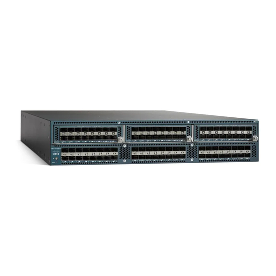
Cisco UCS 6296 UP Fabric Interconnect Chassis The Cisco UCS 6296 UP chassis is 2 RU or 3.47 inches (8.8 cm) tall, 17.3 inches (43.9 cm) wide, and 29.5 inches (74.9 cm) deep. It is designed to be mounted in a standard 19-inch wide rack. The front of the switch has a USB port, four Ethernet and ports (two cross-connect ports, one management port, and one console port), two power supplies, and four fan modules. - Page 15 USB port UCS cross connect port The rear of the Cisco UCS 6296 UP chassis has 48 fixed 10-Gigabit Ethernet data ports on the bottom and three slots for optional expansion modules on top. Cisco UCS 6200 Series Fabric Interconnect Hardware Installation Guide...
-
Page 16: Ucs Unified Port Expansion Module
There are 32 to 48 ports on the Cisco UCS 6248 UP, depending on whether an expansion module is installed. Each individual port is numbered, and groups of ports are numbered based on their function. The ports are numbered from top to bottom and left to right. -
Page 17: Cisco Ucs 6296 Up Port Numbering
Cisco UCS 6296 UP Port Numbering Each port on the Cisco UCS 6296 UP is numbered, and groups of ports are numbered based on their function. The ports are numbered top to bottom and left to right. The 48 fixed ports support 8-, 4-, 2-, or 1-Gbps Fibre Channel transceivers and 1- or 10-Gigabit Ethernet transceivers. -
Page 18: Power Supplies
If the cabling is asymmetric, the maximum number of VIFs available is the smaller of the two cabling configurations. For more information on the maximum number of VIFs for your Cisco UCS environment, see the Configuration Limits document for your hardware and software configuration. - Page 19 Product Overview Power Supplies Figure 12: AC Power Supply for the Cisco UCS 6248 UP Fabric Interconnect Fault LED Power LED Figure 13: DC Power Supply for the Cisco UCS 6248 UP Fabric Interconnect Amber LED indicates a Green LED indicates the failure condition.
- Page 20 Product Overview Power Supplies Figure 14: Power Supply for the Cisco UCS 6296 UP Switch Failure (top) and Power Release lever (bottom) LEDs Handle Table 3: Power Supply LED Descriptions Power Supply Condition Power LED Status Fail LED Status No AC power to all power supplies.
-
Page 21: Fan Module
Fan Module Fan Module The Cisco UCS 6248 UP fabric interconnect has slots for two fan modules (also called fan trays). Each fan module houses four fans. The combination of four fans per module and two modules provides the chassis with eight fans. -
Page 22: Led Descriptions
The bicolor fan module LED indicates fan tray health. Green indicates normal operation, while amber indicates a fan failure. LED Descriptions The fabric interconnect has three chassis status LEDs. Table 4: LEDs for the Cisco UCS Fabric Interconnect Location Function Color... -
Page 23: Port Level Leds
There are port activity LEDs on the chassis and on the expansion modules. Table 5: Port LEDs Color Description Green (blinking) Link is up, enabled, and active. Amber Link is administratively disabled. Amber (blinking) POST or operational error. Link is down. Cisco UCS 6200 Series Fabric Interconnect Hardware Installation Guide OL-24475-03... -
Page 24: Supported Transceivers
The high bandwidth of 10-Gigabit Ethernet poses challenges to transmissions that are met by the transceiver and cabling options supported by the Cisco UCS 6200 platform. The enhanced SFP+ 10-Gigabit Ethernet transceiver module is a bidirectional device with a transmitter and receiver in the same physical package. -
Page 25: Sfp Transceivers
802.3X/802.1Qbb Priority Pauses. SFP-10G-LR is supported between fabric interconnect and I/O Module, but the 300 m limit still applies. SFP+ Copper Cables Copper cables are available for use with the 10-Gigabit Ethernet SFP+ module. Cisco UCS 6200 Series Fabric Interconnect Hardware Installation Guide OL-24475-03... -
Page 26: Sfp Fibre Channel Transceivers
SFP-H10GB-ACU10M= 10GBASE-CU SFP+ 10-meter cable On the Cisco UCS 6200 platforms, you can use an innovative Twinax copper cable that connects to standard SFP+ connectors for in-rack use, and on optical cable for longer cable runs. For in-rack or adjacent-rack cabling, the Cisco UCS 6200 platform supports SFP+ direct-attach 10-Gigabit Ethernet copper, which integrates transceivers with Twinax cables into an energy efficient, low-cost, and low-latency solution. - Page 27 The maximum length of fiber optic runs from the fabric interconnect to a chassis is limited to 300 meters. This restriction is imposed by the use of 802.3X/802.1Qbb Priority Pauses. Cisco UCS 6200 Series Fabric Interconnect Hardware Installation Guide OL-24475-03...
- Page 28 Product Overview SFP Fibre Channel Transceivers Cisco UCS 6200 Series Fabric Interconnect Hardware Installation Guide OL-24475-03...
-
Page 29: Installing The Cisco Ucs 6200 Series Fabric Interconnect
Required Equipment, on page 24 • Unpacking and Inspecting the Cisco UCS 6200 Series Fabric Interconnect, on page 24 • Installing the Cisco UCS 6248 UP Chassis in a Cabinet or Rack, on page 25 • Grounding the System, on page 28 •... -
Page 30: Installation Options
• Disconnect all power and external cables before lifting the system. • Have two people to lift the system. The Cisco UCS 6248 UP weighs 35 pounds (15.9 kg). The Cisco UCS 6296 weighs 35 pounds (15.88 kg). The Cisco UCS 6296 UP weighs 50 pounds (22.68 kg). -
Page 31: Installation Guidelines
If available, you can use an uninterruptible power supply (UPS) to protect against power failures. Avoid UPS types that use ferroresonant technology. These UPS types can become unstable with systems such as the Cisco UCS 6200 Series Fabric Interconnect, which can have substantial current draw fluctuations because of fluctuating data traffic patterns. -
Page 32: Cabinet And Rack Requirements
Note Do not use racks that have obstructions (such as power strips), because the obstructions could impair access to field-replaceable units (FRUs). The Cisco RP series PDUs when mounted in a Cisco R Series Rack should not obstruct FRU replacement. -
Page 33: Requirements Specific To Perforated Cabinets
Installing the Cisco UCS 6200 Series Fabric Interconnect Requirements Specific to Perforated Cabinets • The minimum vertical rack space per Cisco UCS 6248 UP chassis must be one RU (rack unit), equal to 1.75 in. (4.4 cm). • The minimum vertical rack space per Cisco UCS 6296 chassis must be two RU (rack unit), equal to 3.5 in. -
Page 34: Cable Management Guidelines
The following additional items (not found in the accessory kit) are required to ground the chassis: • Grounding cable (6 AWG recommended), sized according to local and national installation requirements; the required length depends on the proximity of the Cisco UCS 6200 Series Fabric Interconnect to proper grounding facilities •... -
Page 35: Installing The Cisco Ucs 6248 Up Chassis In A Cabinet Or Rack
Installing the Cisco UCS 6248 UP Chassis in a Cabinet or Rack This procedure describes how to use the rack-mount kit provided with the chassis to install Cisco UCS 6248 UP into a cabinet or rack. All Cisco UCS 6200 Series Fabric Interconnects use the same basic installation procedure. - Page 36 Installing the Cisco UCS 6200 Series Fabric Interconnect Installing the Cisco UCS 6248 UP Chassis in a Cabinet or Rack Procedure Step 1 Install the front rack-mount brackets as follows: a) Position a front rack-mount bracket against the chassis and align the screw holes as shown. Then attach the front rack-mount bracket to the chassis with four M4 screws.
- Page 37 Installing the Cisco UCS 6200 Series Fabric Interconnect Installing the Cisco UCS 6248 UP Chassis in a Cabinet or Rack Figure 18: Installing the Slider Rails Step 4 Insert the chassis into the rack: a) Using both hands, position the chassis with the back of the chassis between the front posts of the rack.
-
Page 38: Grounding The System
Installing the Cisco UCS 6296 Chassis in a Cabinet or Rack This section describes how to use the rack-mount kit provided with the chassis to install Cisco UCS 6296 into a cabinet or rack that meets the requirements. All Cisco UCS 6200 Series Fabric Interconnects use the same installation procedure. - Page 39 Installing the Cisco UCS 6200 Series Fabric Interconnect Installing the Cisco UCS 6296 Chassis in a Cabinet or Rack Front Rack-mount Slider rail rack-mount guides bracket Step 2 Install the rack-mount guides on the chassis as follows: a) Position one of the rack-mount brackets against the side of the chassis and align the screw holes.
-
Page 40: Proper Grounding Practices
When you properly ground systems during installation, you reduce or prevent shock hazards, equipment damage due to transients, and data corruption. Cisco UCS 6200 Series Fabric Interconnect Hardware Installation Guide OL-24475-03... - Page 41 This building contains a standard recommended. Best grounding office environment. recommendations should be followed as much as possible. Cisco UCS 6200 Series Fabric Interconnect Hardware Installation Guide OL-24475-03...
-
Page 42: Preventing Electrostatic Discharge Damage
• Always use an ESD wrist strap and ensure that it makes maximum contact with bare skin. • ESD grounding straps are available with banana plugs, metal spring clips, or alligator clips. All Cisco UCS 6200 Series Fabric Interconnect chassis are equipped with a banana plug connector (identified by the ground symbol next to the connector) somewhere on the front panel. - Page 43 • If you are using a wrist strap with spring or alligator clips, attach either the spring clip or the alligator clip to the ground lug screw: Figure 23: Attaching the ESD Wrist Strap to the Cisco UCS 6248 UP System Ground Lug Screw Open the clip by pressing Side view of the clip its handles together.
-
Page 44: Establishing The System Ground
To connect the system ground, you need the following tools and materials: • Grounding lug—A two-hole standard barrel lug. Supports up to 6 AWG wire. Supplied as part of accessory kit. Cisco UCS 6200 Series Fabric Interconnect Hardware Installation Guide OL-24475-03... -
Page 45: Grounding The Interconnect
All power supplies must be grounded. The receptacles of the AC power cables used to provide power to the chassis must be the grounding type, and the grounding conductors should connect to protective earth ground at the service equipment. Cisco UCS 6200 Series Fabric Interconnect Hardware Installation Guide OL-24475-03... - Page 46 Installing the Cisco UCS 6200 Series Fabric Interconnect Grounding the Interconnect Figure 24: Grounding the Cisco UCS 6296 Fabric Interconnect ESD socket (on switch) Screws, M4, with square cone washers ESD plug NRTL listed grounding lug Grounding cable Close-up of grounding pad on switch Warning When installing or replacing the unit, the ground connection must always be made first and disconnected last.
-
Page 47: Starting The System
Do not connect the Ethernet port to the LAN until the initial system configuration has been performed. For instructions on configuring the system, see the Configuration Guide for the version of Cisco UCS Manager that you are using. The configuration guides are available at the following URL: http://www.cisco.com/en/US/products/ps10281/products_installation_and_configuration_guides_list.html. - Page 48 For a first-time installation, you will need to work with your network manager to determine the following parameters: • System name • Password for the admin account. Choose a strong password that meets the guidelines for Cisco UCS Manager passwords. This password can not be blank. • Management port IP address and subnet mask •...
-
Page 49: Replacing Or Installing Components
Note If you need to install or replace a Cisco UCS 6296 fabric interconnect, you do not need to remove and install the management daughter card. The Cisco UCS 6296 has a nonremovable management daughter card. Removing a Management Daughter Card... - Page 50 Figure 27: Detaching the Management Daughter Card from the Chassis Loosen captive screws until they are no longer Pull the management daughter card part way out attached to the chassis. of the chassis. Cisco UCS 6200 Series Fabric Interconnect Hardware Installation Guide OL-24475-03...
-
Page 51: Installing A Management Daughter Card
Step 2 Tighten both captive screws to the chassis. Step 3 Install both fan modules into the replacement management daughter card. (See Replacing a Fan Module, on page 46.) Cisco UCS 6200 Series Fabric Interconnect Hardware Installation Guide OL-24475-03... -
Page 52: Replacing Or Installing Expansion Modules
Note Install the Cisco UCS 6200 Series Fabric Interconnect chassis in the rack before installing expansion modules. For information about installing the chassis, see Installing the Cisco UCS 6248 UP Chassis in a Cabinet or... -
Page 53: Installing An Expansion Module
Installing the Cisco UCS 6200 Series Fabric Interconnect Installing an Expansion Module Figure 29: Removing an Expansion Module From the Cisco UCS 6248 UP Figure 30: Removing an Expansion Module From the Cisco UCS 6296 Step 5 Place the module on an antistatic mat or antistatic foam if not immediately reinstalling it in another slot. -
Page 54: Replacing Or Installing Power Supplies
Replacing or Installing Power Supplies The Cisco UCS 6300 Series Fabric Interconnect supports two AC or DC power supplies, but may be used with one power supply. Mixing of AC and DC power supplies is not supported. If you need to replace an existing power supply, follow the procedures that explain how to remove and install power supplies. -
Page 55: Wiring A Dc Power Connector
Depending on the outlet receptacle on your power distribution unit, you may need the optional Note jumper power cord to connect the Cisco UCS 6300 Series Fabric Interconnect to your outlet receptacle. See Cabinet Jumper Power Cords, on page Step 5 Connect the other end of the power cable or cables to a power source. -
Page 56: Fan Modules
Pull the fan module clear of the chassis and set it down on antistatic foam or place it in an antistatic bag. Step 5 Hold the replacement fan module with the LED at the bottom. Cisco UCS 6200 Series Fabric Interconnect Hardware Installation Guide OL-24475-03... -
Page 57: Preparing A Fabric Interconnect For Removal
Disable the Smart Call Home feature in the Cisco UCS domain. d) Decommission every attached chassis in the Cisco UCS domain. For details, see the Configuration Guide for the version of Cisco UCS Manager that you are using. The configuration guides are available at the following URL: http://www.cisco.com/en/US/products/ps10281/products_installation_and_configuration_guides_list.html... -
Page 58: Removing A Cisco Ucs 6248 Up
Procedure Step 1 Ensure that the weight of the Cisco UCS 6248 UP is fully supported and that the chassis is being held by another person. Step 2 Remove the two screws holding the grounding cable to the chassis. - Page 59 Installing the Cisco UCS 6200 Series Fabric Interconnect Replacing a Fabric Interconnect Use Cisco UCS Manager, either the GUI or the CLI, to perform the software-related tasks mentioned in the following procedure. For additional information, refer to the Cisco UCS Manager Getting Started Guide, the Cisco UCS Manager Infrastructure Management Guide, and the instructional videos available at this URL: http://www.cisco.com/c/en/us/support/servers-unified-computing/ucs-manager/...
- Page 60 If necessary, upgrade the UCS Manager software. If the replacement fabric interconnect is not running the same firmware version as the cluster, the setup utility can upgrade the firmware. Example: Cisco UCS 6200 Series Fabric Interconnect Hardware Installation Guide OL-24475-03...
- Page 61 Fabric Interconnect Mgmt0 IPv4 Address Physical Switch Mgmt0 IP address : xx.xx.xx.xx Apply and save the configuration (select 'no' if you want to re-enter)? (yes/no): yes Applying configuration. Please wait. Cisco UCS 6200 Series Fabric Interconnect Hardware Installation Guide OL-24475-03...
-
Page 62: Interconnect
Upgrading from a Cisco UCS 6248 UP Fabric Interconnect to a Cisco UCS 6296 UP Fabric Interconnect Follow these steps to migrate from a Cisco UCS 6248 UP fabric interconnect to a Cisco UCS 6296 UP fabric interconnect. Before you begin •... -
Page 63: Repacking The Cisco Ucs Fabric Interconnect For Return Shipment
Cisco UCS 6248 UP fabric interconnect. Step 8 Connect the cables from the IOM to the corresponding ports on the Cisco UCS 6296 UP fabric interconnect. Step 9 Disconnect the L1/L2, M1 management, and console cables on the Cisco UCS 6248 UP fabric interconnect. - Page 64 Installing the Cisco UCS 6200 Series Fabric Interconnect Repacking the Cisco UCS Fabric Interconnect for Return Shipment Cisco UCS 6200 Series Fabric Interconnect Hardware Installation Guide OL-24475-03...
-
Page 65: Connecting The Cisco Ucs 6200 Series Fabric Interconnect
• Fibre Channel ports—connect to a SAN. When preparing your site for network connections to the Cisco UCS 6200 Series Fabric Interconnect, consider the following for each type of interface, and gather all the required equipment before connecting the ports: •... -
Page 66: Connecting To The Console Port
The console port on a Cisco UCS fabric interconnect provides an RS232 serial connection over an RJ-45 interface that can be used to perform initial setup on a newly installed system that does not as yet have other connectivity options, perform software recovery tasks when other connectivity is unavailable, monitor network statistics and errors, configure SNMP agent parameters, or download software updates. - Page 67 Connecting the Cisco UCS 6200 Series Fabric Interconnect Connecting to the Console Port Figure 33: Connecting to the Console Port on a Cisco UCS 6296 You can use the console port to perform the following: Before you begin You may have to acquire some or all of the following: •...
-
Page 68: Connecting The Management Port
A session window will start and you will see one of the following prompts: loader> switch(boot)# FI-A(local-mgmt)# You now have terminal access. Depending on the prompt, you may have all Cisco UCS Manager CLI commands or a very abbreviated set of configuration commands. Connecting the Management Port Caution To prevent an IP address conflict, do not connect the management port to the network until the initial configuration is complete. -
Page 69: Connecting To An Sfp+ Ethernet Or Fibre Channel Port
If you cannot install the cable into the transceiver, insert or leave the dust plug in the cable end of the transceiver. Removing a Transceiver Use an SFP+ transceiver to connect to an Ethernet or Fibre Channel port. Cisco UCS 6200 Series Fabric Interconnect Hardware Installation Guide OL-24475-03... -
Page 70: Installing Or Removing Cables Into Sfp Or Sfp+ Transceivers
To prevent damage to the copper cables, do not place more tension on them than the rated limit and do not bend to a radius of less than 1 inch if there is no tension in the cable, or 2 inches if there is tension in the cable. Cisco UCS 6200 Series Fabric Interconnect Hardware Installation Guide OL-24475-03... -
Page 71: Removing A Cable From A Transceiver
If the cable does not install easily, ensure that it is correctly positioned before continuing. For instructions on verifying connectivity, see the Configuration Guide for the version of Cisco UCS Manager that you are using. The configuration guides are available at the following URL: http://www.cisco.com/en/US/products/ps10281/products_installation_and_configuration_guides_list.html... -
Page 72: Connecting To A Fibre Channel Port
Attach an ESD wrist strap and follow its instructions for use. Step 2 If a cable is installed in the transceiver, do the following: a) Record the cable and port connections for later reference. Cisco UCS 6200 Series Fabric Interconnect Hardware Installation Guide OL-24475-03... - Page 73 Insert a dust cover into the port end of the transceiver and place the transceiver on an antistatic mat or into a static-shielding bag if you plan to return it to the factory. Step 5 If another transceiver is not being installed, protect the optical cage by inserting a clean cover. Cisco UCS 6200 Series Fabric Interconnect Hardware Installation Guide OL-24475-03...
-
Page 74: Installing Or Removing Cables Into Sfp Transceivers
If the cable does not install easily, ensure that it is correctly positioned before continuing. For instructions on verifying connectivity, see the Configuration Guide for the version of Cisco UCS Manager that you are using. The configuration guides are available at the following URL: http://www.cisco.com/en/US/products/ps10281/products_installation_and_configuration_guides_list.html... -
Page 75: Maintaining Sfp Transceivers And Fiber-Optic Cables
• Inspect routinely for dust and damage. If damage is suspected, clean and then inspect fiber ends under a microscope to determine if damage has occurred. Cisco UCS 6200 Series Fabric Interconnect Hardware Installation Guide OL-24475-03... - Page 76 Connecting the Cisco UCS 6200 Series Fabric Interconnect Maintaining SFP Transceivers and Fiber-Optic Cables Cisco UCS 6200 Series Fabric Interconnect Hardware Installation Guide OL-24475-03...
-
Page 77: Technical Specifications
32 to 104°F (0 to 40°C) Temperature, operating Temperature, nonoperating -40 to 158°F (-40 to 70°C) Humidity (RH), noncondensing 5 to 95% Altitude 0 to 10000 ft (0 to 3000 m) Cisco UCS 6200 Series Fabric Interconnect Hardware Installation Guide OL-24475-03... -
Page 78: Power Specifications
There are three connectors on the baseboard, two for power delivery, and one for power supply control signals. Table 15: Specifications for the Cisco UCS 6248UP DC Power Supply (UCS-PSU-6248UP-DC=) DC Power Supply Properties Cisco UCS 6248UP fabric interconnect... -
Page 79: Transceiver Specifications
Table 19: Environmental Conditions and Power Requirement Specifications for the 10-Gigabit Ethernet SFP+ Transceiver Module Parameter Symbol Minimum Maximum Storage temperature -40°C (-40°F) 85°C (185°F) Case temperature 0°C (32°F) 70°C (158°F) Cisco UCS 6200 Series Fabric Interconnect Hardware Installation Guide OL-24475-03... -
Page 80: General Specifications For Cisco Fibre Channel Sfp Transceivers
3.5 V General Specifications for Cisco Fibre Channel SFP Transceivers The table below lists the general specifications for Cisco Fibre Channel SFP transceivers at 4 Gbps. Table 20: General Specifications for Cisco Fibre Channel SFP Transceivers at 4 Gbps Description... -
Page 81: Cable And Port Specifications
• Supported AC Power Cords and Plugs, on page 73 Accessory Kit for the Cisco UCS Fabric Interconnect The Cisco UCS 6248 Fabric Interconnect accessory kit includes the following items: • 2 slider rails • 2 rack-mount guides • 2 rack-mount brackets •... -
Page 82: Console Cable
Signal Name Console Port The console port is an asynchronous RS-232 serial port with an RJ-45 connector. The table below lists the pinouts for the console port on the Cisco UCS 6200 Series Fabric Interconnect. Table 23: Console Port Pinouts Signal... -
Page 83: Supported Ac Power Cords And Plugs
Note Only the regular power cords or jumper power cords provided with the chassis are supported. Argentina Power Cord—SFS-250V-10A-AR Plug—250 VAC 10 A IRAM 2073 Length—8.2 feet / 2.5 meters Cisco UCS 6200 Series Fabric Interconnect Hardware Installation Guide OL-24475-03... -
Page 84: Australia And New Zealand
Cordset rating: 10 A, 250 V/500V Length: 2500mm Connector: Plug: EL 701C EL 206 (IEC 60320/C15) A.S. 3112-2000) Peoples Republic of China Power Cord—SFS-250V-10A-CN Plug—250 VAC 10 A GB 2009 Length—8.2 feet / 2.5 meters Cisco UCS 6200 Series Fabric Interconnect Hardware Installation Guide OL-24475-03... -
Page 85: Taiwan
Cordset rating: 10A/16 A, 250 V Length: 8 ft 2 in. (2.5 m) Plug: M2511 Connector: VSCC15 India, South Africa, and United Arab Emirates Power Cord—SFS-250V-10A-ID Plug—250 VAC 16A EL-208 Length—8.2 feet / 2.5 meters Cisco UCS 6200 Series Fabric Interconnect Hardware Installation Guide OL-24475-03... -
Page 86: Israel
Figure 40: SFS-250V-10A-IS Cordset rating 10A, 250V/500V MAX (2500 mm) Connector: EL 701B Plug: (IEC60320/C13) EL 212 (SI-32) Italy Power Cord—CAB-9K10A-IT Plug—250 VAC 10 A CEI 23-16 Length—8.2 feet / 2.5 meters Cisco UCS 6200 Series Fabric Interconnect Hardware Installation Guide OL-24475-03... -
Page 87: North America
CAB-AC-250V/13A Power Cord—CAB-AC-250V/13A Plug—250 VAC 13 A IEC60320 Length—6.6 feet / 2.0 meters Figure 42: CAB-AC-250V/13A CAB-N5K6A-NA Power Cord—CAB-N5K6A-NA Plug—250 VAC 13 A NEMA 6-15 Length—8.2 feet / 2.5 meters Cisco UCS 6200 Series Fabric Interconnect Hardware Installation Guide OL-24475-03... -
Page 88: Switzerland
Cordset rating: 10 A, 250 V Length: 8.2 ft Plug: NEMA 6-15P Connector: IEC60320/C13 United Kingdom Power Cord—CAB-9K10A-UK Plug—250 VAC 10 A BS1363 (13 A fuse) Length—8.2 feet / 2.5 meters Cisco UCS 6200 Series Fabric Interconnect Hardware Installation Guide OL-24475-03... -
Page 89: Cabinet Jumper Power Cords
Plug— 250 VAC 10 A, C13-C14 Connectors Length—2.2 feet / 0.7 meters Figure 46: CAB-C13-C14-JMPR Jumper Power Cord—CAB-C13-C14-AC Plug— 250 VAC 10 A, C13-C14 Connectors Length—9.8 feet / 3 meters Cisco UCS 6200 Series Fabric Interconnect Hardware Installation Guide OL-24475-03... - Page 90 Cable and Port Specifications Cable and Port Specifications Figure 47: CAB-C13-C14-AC Jumper Power Cord—CAB-C13-C14-2M Plug— 250 VAC 10 A, C13-C14 Connectors Length—6.6 feet / 2 meters Figure 48: CAB-C13-C14-2M Cisco UCS 6200 Series Fabric Interconnect Hardware Installation Guide OL-24475-03...
-
Page 91: Site Planning And Maintenance Records
Table 24: Site Planning Checklist Task No. Planning Activity Verified By Time Date Space evaluation: • Space and layout • Floor covering • Impact and vibration • Lighting • Maintenance access Cisco UCS 6200 Series Fabric Interconnect Hardware Installation Guide OL-24475-03... - Page 92 • Dedicated circuit for power supply • Dedicated (separate) circuits for redundant power supplies • UPS for power failures Grounding evaluation: • Circuit breaker size • CO ground (AC- powered systems) Cisco UCS 6200 Series Fabric Interconnect Hardware Installation Guide OL-24475-03...
-
Page 93: Contact And Site Information
Use the following worksheet to record contact and site information. Table 25: Contact and Site Information Contact person Contact phone Contact e-mail Building/site name Data center location Floor location Address (line 1) Address (line 2) Cisco UCS 6200 Series Fabric Interconnect Hardware Installation Guide OL-24475-03... -
Page 94: Chassis And Module Information
System IP address System IP netmask Hostname Domain name IP broadcast address Gateway/router address DNS address Modem telephone number Table 27: Module Information Slot Module Type Module Serial Number Notes Fixed Expansion Cisco UCS 6200 Series Fabric Interconnect Hardware Installation Guide OL-24475-03... - Page 95 Site Planning and Maintenance Records Table 28: Fabric Interconnect Port Connection Record Fabric Interconnect A or B Connected to Slot Port Chassis Port LAN or SAN Port Connection Pin Group Channel Notes Group Cisco UCS 6200 Series Fabric Interconnect Hardware Installation Guide OL-24475-03...
- Page 96 Site Planning and Maintenance Records Site Planning and Maintenance Records Fabric Interconnect A or B Connected to Slot Port Chassis Port LAN or SAN Port Connection Pin Group Channel Notes Group Cisco UCS 6200 Series Fabric Interconnect Hardware Installation Guide OL-24475-03...
-
Page 97: Troubleshooting Hardware Components
You can set SNMP traps to monitor fans, power supplies, and temperature settings, or to test a call home application. For details, see the Configuration Guide for the version of Cisco UCS Manager that you are using. The configuration guides are available at the following URL: http://www.cisco.com/en/US/products/ps10281/products_installation_and_configuration_guides_list.html... -
Page 98: System Hardware Best Practices
• Make a copy of the running configuration to CompactFlash for a safe backup. • Never use the init system CLI command unless you understand that you will lose the running and startup configuration as well as the files stored on bootflash:. Cisco UCS 6200 Series Fabric Interconnect Hardware Installation Guide OL-24475-03...