RIDGID SeekTech SR-20 Operator's Manual
Locators
Hide thumbs
Also See for SeekTech SR-20:
- Operating instructions manual (31 pages) ,
- Operator's manual (108 pages) ,
- Operator's manual (20 pages)
Table of Contents
Advertisement
Quick Links
SR-20
Tech
WARNING!
Read this Operator's Man-
ual carefully before using
this tool. Failure to under-
stand and follow the con-
tents of this manual may
result in electrical shock,
fire, and/or serious per-
sonal injury.
Operator's Manual
SR
Locators
™
SR-24 is used to refer to both the SR-24
and the SR-20 throughout this manual. The
SR-24 has integrated GPS and Bluetooth
technology. The SR-20 does not, but is oth-
erwise functionally identical.
Original Instructions – English – 1
®
Advertisement
Table of Contents

Related Manuals for RIDGID SeekTech SR-20


Summary of Contents for RIDGID SeekTech SR-20
- Page 1 Operator’s Manual Locators ™ SR-20 Tech WARNING! Read this Operator’s Man- ual carefully before using SR-24 is used to refer to both the SR-24 this tool. Failure to under- and the SR-20 throughout this manual. The stand and follow the con- SR-24 has integrated GPS and Bluetooth tents of this manual may ®...
-
Page 2: Table Of Contents
Table of Contents Introduction Regulatory Statements ����������������������������������������������������������������������������������������������������������������������������������������������� 4 Safety Symbols ����������������������������������������������������������������������������������������������������������������������������������������������������������� 4 General Safety Rules Work Area Safety �������������������������������������������������������������������������������������������������������������������������������������������������������� 5 Electrical Safety ���������������������������������������������������������������������������������������������������������������������������������������������������������� 5 Personal Safety ���������������������������������������������������������������������������������������������������������������������������������������������������������� 5 Equipment Use and Care ������������������������������������������������������������������������������������������������������������������������������������������� 6 Pre-Operation Inspection Specific Safety Information SR‑24/SR‑20 Safety ��������������������������������������������������������������������������������������������������������������������������������������������������� 7 System Overview Description �����������������������������������������������������������������������������������������������������������������������������������������������������������������... - Page 3 Main Menu Setting the Frequency ����������������������������������������������������������������������������������������������������������������������������������������������� 33 Bluetooth ����������������������������������������������������������������������������������������������������������������������������������������������������������������� 34 Connecting to a Transmitter with Bluetooth��������������������������������������������������������������������������������������������������������������� 37 Transmitter Control Screen ��������������������������������������������������������������������������������������������������������������������������������������� 38 SD Card �������������������������������������������������������������������������������������������������������������������������������������������������������������������� 40 Units of Measurement ���������������������������������������������������������������������������������������������������������������������������������������������� 44 LCD Contrast ������������������������������������������������������������������������������������������������������������������������������������������������������������ 44 Custom Frequencies ������������������������������������������������������������������������������������������������������������������������������������������������� 44 Settings IO Menu ��������������������������������������������������������������������������������������������������������������������������������������������������������������������...
-
Page 4: Regulatory Statements
Introduction Safety Symbols In this operator’s manual and on the product, safety sym‑ The warnings, cautions, and instructions dis- bols and signal words are used to communicate import‑ cussed in this operator’s manual cannot cover ant safety information� This section is provided to im‑ all possible conditions and situations that may prove understanding of these signal words and symbols�... -
Page 5: General Safety Rules
General Safety Rules Personal Safety • Stay alert, watch what you are doing, and use com- WARNING mon sense when operating equipment. Do not use equipment while you are tired or under the influence of drugs, alcohol, or medication� A moment of inattention while operating equipment may result in serious per‑... -
Page 6: Equipment Use And Care
Pre-Operation Inspection Equipment Use and Care • Do not force equipment. Use the correct equipment WARNING for your application� The correct equipment will do the job better and safer at the rate for which it is designed� • Do not use equipment if the power switch does not turn it on and off. -
Page 7: Specific Safety Information
The SR-20 ® does not, but is otherwise functionally identical. The RIDGID SeekTech SR‑24 receiver gives utility locat‑ ing professionals the information they need to confident‑ This section contains important safety information that is specific to the SeekTech SR-24/SR-20. Read ly determine the position of underground utilities�... -
Page 8: Standard Equipment
SeekTech SR-24 and SR-20 Specifications SeekTech SR-24 Specifications Dimensions Bluetooth Length 285 mm [11�2 in] Type Class 1 Width 109 mm [4�3 in] Profile RFCOMM Height 790 mm [31�1 in] Transmit power 19�1 dBm Weight without batteries 1�5 kg [3�3 lb] Operating spectrum 2402 – 2480 MHz Power Receiver sensitivity ‑92 dBm 6 V, 375 mA (SR‑20) -
Page 9: Components
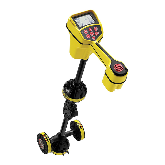
Components Folding Antenna Mast Speaker Unfold the antenna mast and lock the folding joint into Handle place� When the job is complete, press the red release latch to fold the antenna mast� Secure the folding mast into the clip for storage or transportation� Battery Compartment Serial Number Label Marker Chips... -
Page 10: Operating Instructions
Keypad magnetic signal and estimating the position of its source� The SR‑24 can locate the signal transmitted SR-24 Keypad by a RIDGID SeekTech transmitter or Sonde, other manufacturer’s transmitters, or passive signals from Key Function surrounding metallic conductors� Power Key/Right Arrow Key 1�... -
Page 11: Powering The System
Powering the System Receiver Operation Modes Battery operation time varies with battery rating and use� The SR‑24 can operate using two modes: Line Trace Four size C, alkaline batteries can power the SR‑24 for Mode and Sonde Mode� 10 to 15 hours� Line Trace Mode Use batteries that are all the same type. -
Page 12: Audio
Audio Sonde Mode Use Sonde Mode to locate a sonde that is inside a pipe, Volume Control conduit, or tunnel� To increase and decrease the volume level of the SR‑24’s audio cues, first press the Volume Key � You can then Sonde Mode Frequencies either press the Volume Key to cycle through volume set‑... -
Page 13: Display Elements
Display Elements Line Trace Mode Display The display elements shown below appear in Passive Line Trace Mode , Active Line Trace Mode , and Radio Broadband Mode � Proximity Number Current Measurement (mA) Currently Set Frequency Battery Status Receiver Operation Mode Backlight Guidance Line GPS Estimated... - Page 14 Line Trace Mode Display Elements Icon Name Description The orientation and offset of the Tracing Line indicate the direction of the target line relative to the position of the receiver� The Tracing Line Distortion Response is enabled by default� When the Tracing Line Distortion Response Tracing Line is enabled the Tracing Line also represents the amount of distortion detected by the receiver and the approximate axis of the target line�...
- Page 15 Sonde Mode Display The display elements shown below appear in Sonde Mode � Pipe Direction Signal Angle Signal Strength Battery Status Currently Set Frequency Backlight Receiver Operation Mode Pole GPS Estimated Positional Error Bluetooth SD Card and Usage Bar Graph Measured Depth Zoom Ring Cross Hairs...
- Page 16 Sonde Mode Display Elements Icon Name Description Two sonde equator icons appear along the equator line once the first pole has Sonde Equator been located� Equator Line The equator line represents the equator of the sonde’s field� Zoom Ring The Zoom Ring appears when the receiver moves close to one of the Poles� SD Card and Usage The SD Card and Usage Bar Graph icon indicates the SR‑24 is logging to the Bar Graph...
-
Page 17: Understanding The Display
The Guidance Line appears between the arrows when with the SR‑24 manual pack or can be viewed online: the receiver is aligned with the target line� www�RIDGID�com/us/en/instructional‑videos The Guidance Line gets longer as the receiver aligns with the direction of the target line� For best guidance accuracy, align the Tracing Line and Guidance Line be‑... - Page 18 Distortion Note: To change the Tracing Line Distortion Response sensitivity settings, refer to the Customizing Display Electromagnetic receivers like the SR‑24 require a sig‑ Elements section. nal directly from the target utility without modification by environmental factors to obtain optimal accuracy� When the Distortion Line is enabled, the tracing line fuzz‑...
-
Page 19: Active Line Tracing
Refer to the Improving the Tracing In Active Line Tracing Mode, the SR‑24 detects signals Circuit section for more information on grounding. generated by a line transmitter, such as the RIDGID 4� Begin tracing the line� SeekTech ST‑33Q+� Transmitters can energize a target... -
Page 20: Induction
Induction Induction and Air-Coupling To induce a signal onto the target line, place the trans‑ WARNING mitter over and in line with the target line� The transmit‑ Air-coupling can lead to false locates. ter must be oriented with respect to the line, as shown below, to operate properly (orientation is specific to the With Induction, the transmitter broadcasts a signal in all transmitter model)�... -
Page 21: Tracing The Target Line
DVD included with the SR‑24 manual pack or can be plugged in. viewed online: 2� Set the transmitter’s frequency and press the www�RIDGID�com/us/en/instructional‑videos Frequency Key on the SR‑24 to set the receiver to the same frequency� Note: Make sure you have selected an Active Line... -
Page 22: Passive Line Tracing
Passive Line Tracing Passive Power Power Frequencies are used to locate signals from CAUTION AC power lines� In addition to 50 Hz and 60 Hz power Due to the nature of Passive Line Tracing, measured frequencies, the SR‑24 also has an exclusive broadband depth may not be accurate. -
Page 23: Omniseek
Refer to the SR‑20 Instructional Video for a demonstra‑ tion of how to confirm accuracy of the locate and make your locates accurate and efficient� The video is on a DVD included with the SR‑24 manual pack or can be viewed online: www�RIDGID�com/us/en/instructional‑videos English – 23... -
Page 24: Sonde Locating
Sonde Locating Locating the Sonde The primary means of locating the Sonde is by finding Sondes come in different shapes and sizes and are the point where its signal is strongest� The SR‑24 also often used to locate non‑con ductive pipes and conduits� has graphical icons that can be used to help find the Some can be floated down a line and others can be at‑... - Page 25 Using the SR-24’s Mapping Feature 4� Locate the second Pole� The SR‑24’s mapping feature provides a fast, intui‑ Move the receiver a few inches off the Pole until the tive way to find the Sonde’s position underground� The Pipe Direction appears� Two Sonde Equator icons Sonde’s dipole field is similar to the Earth’s magnetic appear along the Equator Line once the first Pole field, with two Poles and an Equator�...
- Page 26 Equator Pole Pole The RIDGID NaviTrack FloatSonde floats with the Pole pointing straight up� Some other floating Sondes float with the Sonde axis in line with the pipe� To locate a Sonde in a vertical orientation, center the Pole icon in the Active View Area�...
-
Page 27: Depth
Depth Depth Average In addition to real‑time depth measurement, the Depth CAUTION Average feature is useful when the SR‑24 has variable For the depth to display correctly, the mode must be depth readings� set correctly. Sonde frequencies and Line Trace fre- The Depth Average is a report that averages real‑time quencies can sometimes be the same. -
Page 28: Improving And Confirming Accuracy
Improving and Confirming Depth Alerts Accuracy Under normal operating conditions, using Depth Average can improve the accuracy of the locate by displaying av‑ DANGER eraged data� However, conditions such as distortion, noisy environments, and clipping may affect accuracy� Exposing the utility is the only way to be certain of its location. -
Page 29: Signal Strength
Signal Strength No Signal Icon If the Tracing Line cannot be centered or if it moves You can enable the No Signal icon to display when across the screen erratically, the SR‑24 may not be re‑ there is no meaningful signal� The No Signal icon gives a ceiving a clear signal, stable measured depth, or a reli‑... - Page 30 Center Signal Strength Signal Focus Control Select the Center Signal Strength option to display the Signal Focus Control acts as a magnifying glass on the Signal Strength in the center of the screen� The Center signal� It narrows the sample bandwidth and displays Signal Strength option makes the Signal Strength easier more stable incoming signals, allowing the SR‑24 to to see when locating using Signal Strength alone�...
-
Page 31: Tracing Circuit
Refer to the SR‑20 Instructional Video for a demonstra‑ tion of how to confirm accuracy of the locate and make your locates accurate and efficient� The video is on a DVD included with the SR‑24 manual pack or can be viewed online: www�RIDGID�com/us/en/instructional‑videos English – 31... -
Page 32: Main Menu
Main Menu Below is a map of the top level Main Menu� The contents of the expanded Settings menu appear in the next section of this manual� Sonde Frequencies Active Line Trace Frequencies Passive Power Frequencies Passive Radio Frequencies + OmniSeek Options Bluetooth (SR-24 only) Search for Devices... -
Page 33: Setting The Frequency
Setting the Frequency Activating Inactive Frequencies The instructions for selecting frequencies and activating Inactive frequencies are preprogrammed frequencies inactive frequencies from the Main Menu are the same that can be activated for specific uses� Inactive frequen‑ for Active Line Trace, Passive Power, Passive Radio cies appear in the Main Menu with the box next to the Frequency Broadband, OmniSeek, and Sonde frequen‑... -
Page 34: Bluetooth
RFCOMM profile, including many smart phones, Bluetooth device try the alternate method from the tablets, and GPS units� Refer to www�RIDGID�com/SR24 SR‑24� To initiate the Bluetooth connection from the for a list of some models that have been tested to work SR‑24’s Main Menu, follow these steps:... - Page 35 Disconnecting Bluetooth Bluetooth Pin There are two ways to disconnect the SR‑24 and your Some Bluetooth devices require a pin to connect to the Bluetooth device� Disconnect Bluetooth from your SR‑24� If a pin is necessary, enter the SR‑24’s pin into Bluetooth device or from the SR‑24’s Main Menu�...
- Page 36 Bluetooth Auto-Connect 3� Press the Select Key to open the Bluetooth Options menu� After connecting for the first time, the SR‑24 no longer requires a pin to connect to that Bluetooth device� When The name of the previously connected device ap‑ the SR‑24 is powered on, it automatically searches for pears with an asterisk below the Search icon any device that has previously connected to�...
-
Page 37: Connecting To A Transmitter With Bluetooth
Connecting to a Transmitter with Bluetooth Power Settings Bluetooth To change the Bluetooth power settings from high (de‑ fault) to low, you must disconnect the SR‑24 and the The following section applies to the SR-24 only. Bluetooth device� Then use the Down Arrow Key from With Bluetooth enabled, the SR‑24 can be used to view the Bluetooth Options menu to highlight the Bluetooth... -
Page 38: Transmitter Control Screen
Transmitter Control Screen Powering the Transmitter When the two units are connected with Bluetooth, pow‑ The following section applies to the SR-24 only. ering the receiver on or off automatically powers the When the devices are connected, you can see the trans‑ transmitter on or off�... - Page 39 Direct Connect Mode and Inductive Mode Output Power To remotely set the transmitter to direct connect mode Higher output settings produce a stronger signal for or inductive mode using the receiver, open the transmit‑ the receiver, but reduces battery life for the transmitter� Only use 1,000 mA High Output Mode if using an 18 V ter control screen�...
-
Page 40: Sd Card
GPS units. Refer Initiated Data Output� When User Initiated Data Output is to www.RIDGID.com/SR24 for a list some models that enabled, continuous data logging is turned off, resulting have been tested to work with the SR-24. - Page 41 Refer to www.RIDGID.com/SR24 for current updates and supplemental information pertaining to this product. 2� Open the folder to view files when prompted�...
- Page 42 4� Data log files in the “logs” folder are named according to the date and time they were created, for example: sr24_log_ yyyymmdd_HHMMSS�txt� If data logging is enabled, a new file is created when the SR‑24 is powered on� The log file closes when the SR‑24 is powered off�...
- Page 43 Logged data contains a SeekTech String Identifier or NMEA Identifier Prefix, a Grouping Identifier, a Data Abbreviation, and the Value of the data measured by the SR‑24� SIG or LCD data string begins with the SeekTech String Identifier, fol‑ lowed by the SeekTech Grouping Identifier, Data Abbreviation, and the Value� SeekTech String Identifier Data Abbreviation, Value SeekTech LCD Grouping Identifier...
-
Page 44: Units Of Measurement
Custom Frequencies SD Card Information You can create, store, edit, and delete up to 30 unique, The SD Card Information screen gives you a report of custom frequencies on your SR‑24� You can create cus‑ the amount of space remaining on the SD card� To view tom frequencies ranging from 10 Hz to 35 kHz, making the SD Card Information screen, follow these steps: the SR‑24 compatible with transmitters made by many... - Page 45 Edit Custom Frequencies Note: You can tune the SR-24 to a frequency by watch- ing the Signal Strength in the lower right of the screen To edit custom frequencies, follow these steps: while adjusting the frequency. 1� Open the Custom Frequency menu and highlight 7�...
- Page 46 Commonly Used Frequency List In addition to creating custom frequencies, you can se‑ lect frequencies commonly used by manufacturers of other transmitters� To access the commonly used frequency list, follow these steps: 1� Access the Frequency Input screen through the Custom Frequencies menu�...
-
Page 47: Settings
Settings To open the Settings menu, press the Menu Key and use the Down Arrow Key to navigate to the Settings icon � Press the Select Key to open the Settings menu� Options Settings Data Output (SR‑24 only) Continuous Data Output Disable SIG Data Disable GPS Data Disable LCD Data... -
Page 48: Io Menu
IO Menu Data Selection Use these menus to enable and disable specific compo‑ The following section applies to the SR-24 only. nents of the data output� Disable all or part of a specific The IO feature sends the SR‑24’s locate data to the in‑ data element to reduce the amount of data that is logged ternal SD card, or to a Bluetooth device if one is avail‑... -
Page 49: Sr-24 Gps
The SR‑24 is compatible with Bluetooth 2�0 devices including many phones, tablets, and GPS units� Refer to www�RIDGID�com/SR24 for a list some models that × [13 ft] have been tested to work with the SR‑24�... - Page 50 Signal Quality Time Zone You can monitor the SR‑24’s internal GPS receiver sig‑ Change the time zone setting in the Time Zone screen� nal quality from the GPS menu� To open the GPS menu, To change the time zone, open the Settings menu and follow these steps: press the Down Arrow Key to navigate to the Time...
-
Page 51: Customizing Display Elements
Customizing Display Elements In Active Line Trace Mode and Sonde Mode you can customize the display elements that appear on screen� A checked box means the element is enabled and an unchecked box means it is disabled� From the Customizing Display Elements Screen, press the Select Key to check and uncheck boxes�... - Page 52 Max Signal Indicators To customize display elements, follow these steps: 1� Open the Settings menu and press the Down Arrow The Race Track, Watermark, and Level Pointer work to‑ gether to dynamically give you points of reference for the to navigate to the Customizing Display highest signal the SR‑24 detects�...
- Page 53 Proximity Number and Threshold Proximity Threshold Settings The Proximity Number is designed to increase as the SR‑24 gets closer to the target line� In many cases, max‑ Depth Control imizing the Proximity Number is a more accurate way No threshold, no suppression, and of pinpointing the location of the target line than Signal allows negative depth display�...
-
Page 54: Information Options
Information Options To adjust the Proximity Threshold Control, follow these steps: 1� Activate the Proximity Threshold Control in the dis‑ play settings� Serial Number Note: Refer to the Customizing Display Elements Software Version section for instructions on how to activate the Calibration Date Proximity Threshold Control. -
Page 55: Maintenance And Support
The following accessories have been designed for use with the SR‑24: • RIDGID SeekTech Transmitters • ST‑305 • ST‑510 • ST‑33Q+ • RIDGID SeekTech Inductive Signal Clamp • Sondes • FloatSonde • Battery Sonde • SeeSnake camera integrated Sonde (Flexmitter) English – 55... -
Page 56: Service And Repair
For information on your nearest Ridge Tool Technical Service Department or any service or repair questions: • Contact your local RIDGID distributor� • Go to www�RIDGID�com� • Email the RIDGID Technical Services Department at rtctechservices@emerson�com� • Call 1‑800‑519‑3456 (USA and Canada only)� 56 – English... -
Page 57: Troubleshooting
Troubleshooting Problem Probable Fault Solution Power off the SR‑24 and then power on� Remove SR‑24 locks up during use — the batteries if the unit will not turn off� Replace the batteries if low� Make sure the mode and frequency are correctly set�... -
Page 58: Appendices
Appendices • Distortion. The impact of nearby fields, near‑by con‑ ductors, magnetic flux, or other interference on the Appendix A: Glossary of Terms circular electromagnetic field� Distortion is detected by comparing the information from the Tracing Line, • Active Frequencies. A frequency with the box Proximity Number, Signal Strength, measured depth, checked on the Main Menu �... - Page 59 • Proximity Number . A number that reflects how close the receiver is to the target line when in either Active Line Trace Mode or Passive Line Trace Mode� The Proximity Number is calculated based on the sig‑ nal received by the two Omnidirectional antennas� The Proximity Number increases with signal strength and also increases with decreasing depth�...
-
Page 60: Appendix B: Main Menu Map
Appendix B: Main Menu Map Sonde Frequencies Active Line Trace Frequencies Passive Power Frequencies Passive Radio Frequencies + OmniSeek Options Bluetooth Search for Devices Bluetooth Pin Bluetooth Power Bluetooth Information SD Card Data Logging SD Card Information Units of Measurement LCD Contrast Custom Frequencies Sonde... -
Page 61: Appendix C: Data Logging Abbreviations
Appendix C: Data Logging Abbreviations Data Logging Abbreviations Main SeekTech String Data Menu Grouping Description Identifier Abbreviation Header Identifier FREQ The signal frequency (Hz) of the SR‑24� The magnitude of the signal received by the Lower Antenna in BMAG the range of ‑2 to 2 �... - Page 62 Data Logging Abbreviations Main SeekTech String Data Menu Grouping Description Identifier Abbreviation Header Identifier DSIG The magnitude of the signal received by the SR‑24� The number representing the nearness of the target line to the PROX SR‑24� GRAD The gradient offset in pixels� The value determining the fuzziness of the line being displayed�...
- Page 63 Data Logging Abbreviations Main SeekTech String Data Menu Grouping Description Identifier Abbreviation Header Identifier NMEA: Global Positioning System Fix Data NMEA: Geographical Position, latitude/longitude NMEA: GPS Satellites in View None NMEA: GPS DOP and Active Satellites NMEA: Track Made Good and Ground Speed NMEA: Date and Time Note: For information about NMEA GPS codes, visit www.nmea.org.
- Page 64 RIDGID and the RIDGID logo are trademarks of Ridge Tool Company, registered in the USA and other countries� All other registered and unregistered trademarks and logos mentioned herein are the property of their respective owners� Mention of third‑party products is for informational purposes only and constitutes neither an endorsement nor a recommendation�...