Siemens SIMATIC NETS7-1200 Operating Instructions Manual
Telecontrol cp 1242-7
Hide thumbs
Also See for SIMATIC NETS7-1200:
- Operating instructions manual (74 pages) ,
- Compact operating instructions (50 pages) ,
- Operating instructions manual (55 pages)
Table of Contents
Advertisement
Quick Links
CP 1242-
7
SIMATIC NET
S7-1200 - Telecontrol
CP 1242-7
Operating Instructions
09/2011
C79000-G8976-C247-02
___________________
Preface
___________________
Application and properties
___________________
Displays and connectors
Installing, connecting up and
___________________
commissioning
___________________
Notes on operation
___________________
Configuration
___________________
Technical specifications
___________________
Dimension drawings
___________________
Approvals
___________________
Accessories
___________________
References
___________________
Training, Service & Support
1
2
3
4
5
6
A
B
C
D
E
Advertisement
Table of Contents

Related Manuals for Siemens SIMATIC NETS7-1200


Summary of Contents for Siemens SIMATIC NETS7-1200
- Page 1 ___________________ CP 1242- Preface ___________________ Application and properties ___________________ Displays and connectors SIMATIC NET Installing, connecting up and ___________________ commissioning S7-1200 - Telecontrol ___________________ CP 1242-7 Notes on operation ___________________ Configuration Operating Instructions ___________________ Technical specifications ___________________ Dimension drawings ___________________ Approvals ___________________ Accessories...
- Page 2 Note the following: WARNING Siemens products may only be used for the applications described in the catalog and in the relevant technical documentation. If products and components from other manufacturers are used, these must be recommended or approved by Siemens. Proper transport, storage, installation, assembly, commissioning, operation and maintenance are required to ensure that the products operate safely and without any problems.
-
Page 3: Preface
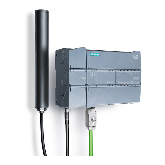
Preface Validity of this manual This document contains information on the following product: CP 1242-7 Order number 6GK7 242-7KX30-0XE0 Hardware product version 1, firmware version V1.0 The device is the communications processor for data transmission using GPRS for the SIMATIC S7-1200. Figure 1 CP 1242-7 At the top right behind the hinged cover of the module housing, you will see the hardware... - Page 4 Preface Purpose of the manual This manual describes the properties of this module and supports you when installing and commissioning the device. The necessary configuration steps are described in the form of an overview. You will also find instructions for operation and information about the diagnostics options of the device.
-
Page 5: Table Of Contents
Table of contents Preface ..............................3 Application and properties ......................... 7 Connecting the S7-1200 to a GSM network ..................7 Applications............................8 Modes and communications partners of the CP 1242-7 ...............9 Other properties of the CP ......................10 Performance data ........................10 Requirements for operation ......................12 Configuration examples .......................14 Displays and connectors.......................... - Page 6 Table of contents Using the telecontrol instructions ....................46 Configuring the telecontrol instructions..................47 5.4.1 TC_CON: Establish connection via the GSM network..............47 5.4.2 TC_DISCON: Terminate connection via the GSM network ............51 5.4.3 TC_SEND: Send data via the GSM network................53 5.4.4 TC_RECV: Receive data via the GSM network ................
-
Page 7: Application And Properties
● 1 900 MHz In countries in which the CP is approved, you will find this on the Internet on the pages of Siemens Automation Customer Support under the following entry ID: 45605894 (http://support.automation.siemens.com/WW/view/en/45605894) On the Internet page, select the "Entry list" tab and the "Certificates" entry type. -
Page 8: Applications
Application and properties 1.2 Applications Applications The CP 1242-7 is intended for use in an industrial environment. The following applications are supported by the CP: Telecontrol applications ● Sending messages by SMS The function is not dependent on the operating mode of the CP. Via the CP 1242-7, the CPU of a remote S7-1200 station can receive SMS messages from the GSM network or send messages by SMS to a configured mobile phone or an S7-1200. -
Page 9: Modes And Communications Partners Of The Cp 1242-7
Application and properties 1.3 Modes and communications partners of the CP 1242-7 Modes and communications partners of the CP 1242-7 Modes and communications partners of the CP For communication with the CP 1242-7 via GPRS, the CP is set to one of the following modes: ●... -
Page 10: Other Properties Of The Cp
Application and properties 1.4 Other properties of the CP Other properties of the CP Other services and functions of the CP 1242-7 ● Time-of-day synchronization of the CP via the Internet You can set the time on the CP as follows: –... - Page 11 Application and properties 1.5 Performance data Number of simultaneous connections in "Telecontrol" mode ● 1 reserved connection to the telecontrol server, for example for TeleService When connection establishment is active also: ● Max. 5 telecontrol connections (TCON_wdc) ● Max. 5 UDP connections (send only) Number of simultaneous connections in "GPRS direct"...
-
Page 12: Requirements For Operation
Install HSP0003001 in STEP 7 using the menu command "Options" > "Support packages". You can install the support package from your local file system if it is already stored there or from the Internet pages of Siemens Automation Customer Support. You will find HSP0003001 at one of the following addresses: –... - Page 13 Application and properties 1.6 Requirements for operation Software for TeleService functions ● STEP 7 as of version V11.0 SP1 For STEP 7 V11.0 SP1, you also require support package "CP 1242-7" (HSP0003001). ● For the switching station: – For configuration with telecontrol server: The "TELECONTROL SERVER BASIC"...
-
Page 14: Configuration Examples
Application and properties 1.7 Configuration examples Configuration examples Below, you will find configuration examples for stations with a CP 1242-7. Sending messages by SMS Figure 1-1 Sending messages by SMS from an S7-1200 station A SIMATIC S7-1200 with a CP 1242-7 can send messages by SMS to a mobile phone or a configured S7-1200 station. - Page 15 Application and properties 1.7 Configuration examples Telecontrol by a control center Figure 1-2 Communication between S7-1200 stations and a control center In telecontrol applications, SIMATIC S7-1200 stations with a CP 1242-7 communicate with a control center via the GSM network and the Internet. The "TELECONTROL SERVER BASIC"...
- Page 16 Application and properties 1.7 Configuration examples Direct communication between stations Figure 1-3 Direct communication between two S7-1200 stations In this configuration, two SIMATIC S7-1200 stations communicate directly with each other using the CP 1242-7 via the GSM network. Each CP 1242-7 has a fixed IP address. The relevant service of the GSM network provider must allow this.
- Page 17 Application and properties 1.7 Configuration examples TeleService via GPRS In TeleService via GPRS, an engineering station on which STEP 7 is installed communicates via the GSM network and the Internet with the CP 1242-7 in the S7-1200. Since a firewall is normally closed for connection requests from the outside, a switching station between the remote station and the engineering station is required.
- Page 18 Application and properties 1.7 Configuration examples ● Configuration without telecontrol server: The connection runs via the TeleService gateway. The connection between the engineering station and the TeleService gateway can be local via a LAN or via the Internet. Figure 1-5 TeleService via GPRS in a configuration with TeleService gateway CP 1242-7 Operating Instructions, 09/2011, C79000-G8976-C247-02...
-
Page 19: Displays And Connectors
Displays and connectors Opening the housing Location of the display elements and the electrical connectors The LEDs for the detailed display of the module statuses are located behind the upper cover of the module housing. The socket for the power supply is located on the top of the module. The connector for the external antenna is located on the bottom of the module. -
Page 20: Leds
Displays and connectors 2.2 LEDs LEDs LEDs of the module The module has various LEDs for displaying the status: ● LED on the front panel The "DIAG" LED that is always visible shows the basic statuses of the module. ● LEDs below the upper cover of the housing The LEDs below the upper cover provide more detailed information on the module status. - Page 21 Displays and connectors 2.2 LEDs Display of the operating and communication status The LED symbols in the following tables have the following significance: Table 2- 3 Meaning of the LED symbols Symbol LED status ON (steady light) Flashing Not relevant The LEDs indicate the operating and communications status of the module according to the following scheme: Table 2- 4...
-
Page 22: Electrical Connections
Displays and connectors 2.3 Electrical connections DIAG Network Connect Signal TeleService Meaning quality (red / green) (red / green) (green) (green) (yellow / green) No connection to the telecontrol server green No configuration available Connection to the telecontrol server established green green... - Page 23 Displays and connectors 2.3 Electrical connections Figure 2-2 Socket for the 24 V DC power supply Wireless interface for the GSM network An extra antenna is required for GPRS communication in the GSM network. This is connected via the SMA socket of the CP. The SMA socket is located behind the lower front cover of the CP.
- Page 24 Displays and connectors 2.3 Electrical connections CP 1242-7 Operating Instructions, 09/2011, C79000-G8976-C247-02...
-
Page 25: Installing, Connecting Up And Commissioning
Installing, connecting up and commissioning Important notes on using the device Safety notices on the use of the device The following safety notices must be adhered to when setting up and operating the device and during all work relating to it such as installation, connecting up, replacing devices or opening the device. - Page 26 Installing, connecting up and commissioning 3.1 Important notes on using the device WARNING Replacing components EXPLOSION HAZARD SUBSTITUTION OF COMPONENTS MAY IMPAIR SUITABILITY FOR CLASS I, DIVISION 2 OR ZONE 2. WARNING Requirements for the cabinet/enclosure When used in hazardous environments corresponding to Class I, Division 2 or Class I, Zone 2, the device must be installed in a cabinet or a suitable enclosure.
-
Page 27: Warning Overvoltage Protection
Installing, connecting up and commissioning 3.2 Warning overvoltage protection Warning overvoltage protection CAUTION Protection of the external 24 VDC power supply If power is supplied to the module over longer 24 V power cables or networks, the coupling in of strong electromagnetic pulses onto the power supply cables is possible. This can be caused, for example by lightning strikes or switching of higher loads. - Page 28 Installing, connecting up and commissioning 3.3 Installing and commissioning the CP Inserting the SIM card Prior to installation, insert the SIM card in the CP. Step Execution Notes and explanations Release the slide for the SIM card on the bottom of the CP by gently pressing the release pin.
- Page 29 Installing, connecting up and commissioning 3.3 Installing and commissioning the CP Dimensions for installation Figure 3-1 Dimensions for installation of the S7-1200 Table 3- 1 Dimensions for installation (mm) S7-1200 devices Width A Width B * CPU 1211C, CPU 1212C 90 mm 45 mm CPU 1214C...
- Page 30 Installing, connecting up and commissioning 3.3 Installing and commissioning the CP Procedure for installation and commissioning CAUTION Installation location The module must be installed so that its upper and lower ventilation slits are not covered, allowing adequate ventilation. Above and below the device, there must be a clearance of 25 mm to allow air to circulate and prevent overheating.
- Page 31 Installing, connecting up and commissioning 3.3 Installing and commissioning the CP Table 3- 2 Procedure for installation and connecting up Step Execution Notes and explanations Mount the CP on the DIN rail and connect it to Use a 35 mm DIN rail. the module to its right.
-
Page 32: Pin Assignment Of The Socket For The External Power Supply
Installing, connecting up and commissioning 3.4 Pin assignment of the socket for the external power supply Pin assignment of the socket for the external power supply Figure 3-2 Socket for the external 24 VDC power supply (view from above) Table 3- 3 Pin assignment of the socket for the external power supply Labeling Function... -
Page 33: Notes On Operation
Notes on operation CAUTION Minimum clearance to the device The device may only be operated when the distance between the device (or antenna) and user is at least 20 cm. CAUTION Closing the front panels To ensure interference-free operation, keep the front panels of the module closed during operation. - Page 34 Notes on operation 4.1 Connection modes and connection establishment A connection is always established by the CP. If a connection established by the CP is interrupted, the CP automatically attempts to re-establish the connection. Triggering connection establishment for permanent stations ("Telecontrol" mode) In the "Telecontrol"...
-
Page 35: The Wake-Up Sms
Notes on operation 4.2 The wake-up SMS ● Telephone wake-up SMS The wake-up SMS can be sent from a telephone that has a phone number authorized in the STEP 7 project. The telephone must support the CLIP function (transfer of its own call number) and the sending of SMS messages. -
Page 36: Main And Substitute Telecontrol Server
Notes on operation 4.3 Main and substitute telecontrol server ● For telecontrol connections: – Text for the wake-up SMS message for establishing a connection to the telecontrol server: TELECONTROL – Text for the wake-up SMS message for establishing a connection to the main telecontrol server: TELECONTROL MAIN –... - Page 37 1. Copy the database file from the following directory of the main system: Programdata > Siemens > Automation > TCS Basic > Data > "Smsc.sqlite" 2. Insert the database file at the same location in the file system of the substitute system.
-
Page 38: Redial Delay (Step 7)
Notes on operation 4.4 Redial delay (STEP 7) Redial delay (STEP 7) The "Redial delay" parameter of the CP 1242-7 In "Telecontrol" mode, the redial delay is the waiting time between the connection establishment attempts if the telecontrol server cannot be reached. It is configured in STEP 7, parameter group "Operating mode"... -
Page 39: Calling A Teleservice Connection
Notes on operation 4.6 Calling a TeleService connection Communications partner is a telecontrol server The reaction of the CP after data is sent from the CPU to the CP depends on the setting of the RemeoteWdcAddress parameter of the TCON_WDC data block: ●... - Page 40 Notes on operation 4.6 Calling a TeleService connection Requirement for switching the connection The request for connection establishment is triggered by the engineering station. To switch the connection to the remote station, a telecontrol server or a TeleService gateway is required.
-
Page 41: Diagnostics
Downloading firmware New firmware versions If a new firmware version is available for the module, you will find this on the Ethernet pages of the Siemens Automation Customer Support under the following ID: CP 1242-7 Operating Instructions, 09/2011, C79000-G8976-C247-02... -
Page 42: Module Replacement
Notes on operation 4.9 Module replacement 45605894 (http://support.automation.siemens.com/WW/view/en/45605894) On the Internet page, select the "Entry list" tab and the "Download" entry type. You will find the firmware file and a description of the procedure there. You can recognize that firmware is being loaded by the flashing LEDs of the CP, see section LEDs (Page 20). -
Page 43: Configuration
Configuration Configuration in STEP 7 Configuration in STEP 7 You configure the modules, networks and connections in SIMATIC STEP 7. You will find the required version in the section Requirements for operation (Page 12). You can configure a maximum of three CMs/CPs per station. If you insert several modules of the type CP 1242-7 in an S7-1200, you can, for example, establish redundant communications paths. - Page 44 Configuration 5.2 Information required for configuration ● APN Name of the GPRS access point (APN) of the GSM network provider ● APN user name User name for the GPRS access point of the GSM network provider ● APN password Password for the GPRS access point of the GSM network provider ●...
- Page 45 Configuration 5.2 Information required for configuration Information required in "Telecontrol" mode ● Address of the telecontrol server – IP address – Name of the telecontrol server that can be resolved by DNS – Port number The relevant station type-dependent number of the listener port is configured in the telecontrol instructions.
-
Page 46: Using The Telecontrol Instructions
Configuration 5.3 Using the telecontrol instructions CP parameter for configuring the telecontrol server The following parameters from the configuration of the CP 1242-7 are also required for the configuration of the telecontrol server: ● Address and port of the telecontrol server ●... -
Page 47: Configuring The Telecontrol Instructions
Configuration 5.4 Configuring the telecontrol instructions Note the maximum number of parallel connections in the section Performance data (Page 10). NOTICE Connection abort If an existing connection is aborted by the communications partner or due to disturbances on the network, the connection must also be terminated by calling "TC_DISCON". Make sure that you take this into account in your programming. - Page 48 Configuration 5.4 Configuring the telecontrol instructions ● SMS The connection partner is an SMS client. ● Telecontrol connection The connection partner is either a telecontrol server or another station that can be reached via the telecontrol server. A TC_CON establishes exactly one connection. Depending on the mode of the CP 1242-7 and the protocol you are using, a maximum of 3 to 5 simultaneous connections with unique IDs (see below) are supported per CP.
- Page 49 Configuration 5.4 Configuring the telecontrol instructions Explanation of the formal parameters The following table explains all the formal parameters for the TC_CON instruction. Parameter Declaration Data type Possible values Description INPUT BOOL 0, 1 The instruction is started and the status codes initialized on a rising edge.
- Page 50 Configuration 5.4 Configuring the telecontrol instructions The codes BUSY, DONE and ERROR The codes of DONE and ERROR are relevant only when BUSY = 0. BUSY DONE ERROR Meaning No job being executed You will find all other code combinations of DONE and ERROR in the following table. When called, the instruction remains in the BUSY = 1 state for several seconds.
-
Page 51: Tc_Discon: Terminate Connection Via The Gsm Network
Configuration 5.4 Configuring the telecontrol instructions DONE ERROR STATUS Meaning 80F4 Connection endpoint cannot be generated: Repeat the call. If necessary, check the connection parameters. 80F6 Format error of a parameter in the called data block (wrong length, wrong format or invalid value) Check the configuration of the "TC_CON..."... - Page 52 Configuration 5.4 Configuring the telecontrol instructions Explanation of the formal parameters The following table explains all the formal parameters for the TC_DISCON instruction Parameter Declaration Data type Possible values Description INPUT BOOL 0, 1 The instruction is started and the status codes initialized on a rising edge.
-
Page 53: Tc_Send: Send Data Via The Gsm Network
Configuration 5.4 Configuring the telecontrol instructions The codes DONE, ERROR and STATUS The following table shows the condition codes formed based on DONE, ERROR and STATUS that must be evaluated by the user program. DONE ERROR STATUS Meaning 0000 Job executed without errors 7000 No job processing active (first instruction call) 7001... - Page 54 Configuration 5.4 Configuring the telecontrol instructions The destination address (connection partner) for the data to be sent is configured in the TC_CON instruction. Call interface in FBD representation Explanation of the formal parameters The following table explains all the formal parameters for the TC_SEND instruction. Parameter Declaration Data type...
- Page 55 Configuration 5.4 Configuring the telecontrol instructions Parameter Declaration Data type Possible values Description ERROR OUTPUT BOOL 0: - Error code 1: Error For the meaning in conjunction with the parameters DONE and STATUS, refer to Codes of the instruction. STATUS OUTPUT WORD Status code...
-
Page 56: Tc_Recv: Receive Data Via The Gsm Network
Configuration 5.4 Configuring the telecontrol instructions DONE ERROR STATUS Meaning 80EA Error message from remote partner: Check the connection partner. Enable the "TC_RECV" instruction on the communications partner. If necessary, terminate the connection with TC_DISCON and establish it again with ... - Page 57 Configuration 5.4 Configuring the telecontrol instructions The ID parameter references the GPRS connection. The value of ID must correspond to the value used for ID by TC_CON. The InterfaceID parameter references the GPRS interface of the required local CP. The value must be the same as that used by TC_CON for InterfaceID.
- Page 58 Configuration 5.4 Configuring the telecontrol instructions Parameter Declaration Data type Possible values Description BUSY OUTPUT BOOL 0: Execution of the instruction Display of the processing status of the not started, completed or instruction aborted 1: The instruction is executing DONE OUTPUT BOOL 0: -...
-
Page 59: Tc_Config: Transferring Configuration Data To A Gprs Communications Module
Configuration 5.4 Configuring the telecontrol instructions DONE ERROR STATUS Meaning 80F5 Invalid connection endpoint: Connection establishment by TC_CON failed. Connection terminated by remote partner: First call TC_DISCON. 80F6 Format error of a parameter in the called data block (wrong length, wrong format or invalid value) Check the configuration of the "TC_CON..."... - Page 60 Configuration 5.4 Configuring the telecontrol instructions Explanation of the formal parameters The following table explains all the formal parameters for the TC_CONFIG instruction Parameter Declaration Data type Possible values Description INPUT BOOL 0, 1 The instruction is started and the status codes initialized on a rising edge.
-
Page 61: Other Error Messages
Wrong ID in the parameter fields of the configuration data: Check the "IF_CONF" SDT. 5.4.6 Other error messages Other error messages The following error messages are used for diagnostics purposes. You can obtain more information from the Siemens hotline. DONE ERROR STATUS Meaning 80E0 Internal error 5.4.7... - Page 62 Configuration 5.4 Configuring the telecontrol instructions ● TCON_phone for connections to SMS clients ● TCON_WDC for connections to telecontrol servers or stations that can be reached via the telecontrol server. The parameter assignment of the connection description is made in a data block of the same type as the SDT.
- Page 63 Configuration 5.4 Configuring the telecontrol instructions Byte Parameter Data type Initial value Description 16 ... TSel Array [1...32] Remote transport selector of the connection of Byte When "ActiveEstablished" = 1: With active connection establishment, the T selector of the local partner must be the same as the T selector of the connection partner (passive connection establishment on the remote partner).
- Page 64 Configuration 5.4 Configuring the telecontrol instructions Byte Parameter Data type Initial value Description 6 ... 7 - reserved - RemoteAddress IP_V4 IP address of the connection partner 8 ... 11 ADDR Array [1...4] of IP address of the relevant connection partner Byte 12 ...
- Page 65 Configuration 5.4 Configuring the telecontrol instructions System data types for connections to telecontrol servers or remote stations You can configure the connection to the telecontrol server assigned to the S7-1200 or to a remote station that can be reached via the telecontrol server with TCON_WDC. The address data of the telecontrol server assigned to the CP can be found in STEP 7 in the "Telecontrol interface >...
-
Page 66: If_Conf: Sdt For Telecontrol Configuration Data
Configuration 5.4 Configuring the telecontrol instructions 5.4.8 IF_CONF: SDT for telecontrol configuration data Parameter assignment of the system data type IF_CONF for the TC_CONFIG instruction The CONFIG parameter of the TC_CONFIG instruction references the memory area with the configuration data of the CP 1242-7 to be modified. The configuration data stored in a data block is described as a structure of the system data type (SDT) IF_CONF. - Page 67 Configuration 5.4 Configuring the telecontrol instructions Value Meaning Permanent validity of the configuration data Not relevant for the CP 1242-7 Temporary validity of the configuration data, including deleting of existing permanent configuration data The permanent configuration data is replaced by the parameter fields of IF_CONF. Field for the parameter area "GPRS access"...
- Page 68 Configuration 5.4 Configuring the telecontrol instructions Table 5- 8 IF_CONF_TCS_Name Parameter Data type Initial value Description UINT ID of the parameter field Length UINT Length of the parameter field in bytes: 266 Mode UINT Validity (1: permanent, 2: temporary) TcsName - reserved - STRING [254] Name of the telecontrol server that can be resolved by...
- Page 69 Configuration 5.4 Configuring the telecontrol instructions Parameter Data type Initial value Description GPRSmode UINT Mode of the CP: 0 = Telecontrol 1 = GPRS direct TemporaryStation BOOL Bit 0: Temporary connection If this option is selected, the CP only establishes a temporary connection to send data.
- Page 70 Configuration 5.4 Configuring the telecontrol instructions Field for monitoring times In STEP 7, the corresponding data is located in the parameter areas "Acknowledgment monitoring" and Operating mode". Table 5- 13 IF_CONF_TC_Timeouts Parameter Data type Initial value Description UINT ID of the parameter field Length UINT Length of the parameter field in bytes: 12...
- Page 71 Entry of the Public Land Mobile Network (PLMN) of the network provider consisting of Mobile Country Code (MCC) and Mobile Network Code (MNC). Example (test network of Siemens AG): 26276 Field for the "DNS configuration" parameter area Table 5- 16...
- Page 72 Configuration 5.4 Configuring the telecontrol instructions Block for activating / deactivating TeleService users SDT for activating or deactivating TeleService users already configured in the STEP 7 project of the CP. In STEP 7, the corresponding data can be found in the parameter area "TeleService settings"...
- Page 73 Configuration 5.4 Configuring the telecontrol instructions Field for setting the parameters for TeleService access (IP address of the server) Access data of the TeleService server (switching station). In STEP 7, the corresponding data is located in the parameter area "TeleService settings". If there is more than one TeleService server, use the field once per server.
- Page 74 Configuration 5.4 Configuring the telecontrol instructions CP 1242-7 Operating Instructions, 09/2011, C79000-G8976-C247-02...
-
Page 75: Technical Specifications
Technical specifications Table 6- 1 Technical specifications of the CP 1242-7 Technical specifications Order number 6GK7 242-7KX30-0XE0 Wireless interface Antenna connector SMA socket Nominal impedance 50 ohms Wireless connection Maximum transmit power GSM 850, class 4: +33 dBm ±2dBm GSM 900, class 4: +33 dBm ±2dBm ... - Page 76 Technical specifications Technical specifications Effective power loss (typical) from 24 V DC 2.4 W from the S7-1200 backplane bus 24 V DC power supply Min. cable cross section min.: 0.14 mm (AWG 25) Max. cable cross section max.: 1.5 mm (AWG 15) ...
-
Page 77: Dimension Drawings
Dimension drawings Note All dimensions in the drawings are in millimeters. Figure A-1 CP 1242-7 - front view CP 1242-7 Operating Instructions, 09/2011, C79000-G8976-C247-02... - Page 78 Dimension drawings Figure A-2 CP 1242-7 - side view left Figure A-3 CP 1242-7 - view from above CP 1242-7 Operating Instructions, 09/2011, C79000-G8976-C247-02...
-
Page 79: Approvals
The list of countries in which the CP 1242-7 is approved can be found on the Internet at the following address: 45605894 (http://support.automation.siemens.com/WW/view/en/45605894) Overview of approvals and standards The CP 1242-7 has the following approvals and meets the following standards: ●... - Page 80 Postfach 4848 D-90327 Nürnberg Germany You will find the EC Declaration of Conformity for this product on the Internet at the following address: 10805878 (http://support.automation.siemens.com/WW/view/en/10805878) → Tab "Entry List" Filter settings: Entry type: "Certificates" Certificate Type: "Declaration of Conformity" Search items(s): <name of the module>...
- Page 81 Approvals cULus approval Underwriters Laboratories Inc. meets Underwriters Laboratories, Inc.: UL 508 Listed (industrial control devices) Canadian Standards Association: CSA C22.2 Number 142 (process control equipment) FM certification Factory Mutual Research (FM): Approval Standard Class number 3600 and 3611 Approved for use in: Class I, Division 2, Group A, B, C, D, Temperature Class T4A, Ta = 55 °C Class I, Zone 2, Group IIC, Temperature Class T4, Ta = 55 °C...
- Page 82 Approvals Industrial environments The CP was developed for use in industrial environments. Application Requirements for emissions Requirements for immunity Industry EN 61000-6-4:2007 EN 61000-6-2:2005 Electromagnetic compatibility (EMC) The electromagnetic compatibility (EMC) of an electrical device is its capability of functioning as intended in an electromagnetic environment without emitting electromagnetic interference that could impair the operation of other electrical devices in the vicinity.
- Page 83 The S7-1200 products are regularly submitted to the relevant authorities for approvals relating to specific markets and applications. If you require a list of the current approvals for individual devices, consult your Siemens contact. CP 1242-7 Operating Instructions, 09/2011, C79000-G8976-C247-02...
- Page 84 Approvals CP 1242-7 Operating Instructions, 09/2011, C79000-G8976-C247-02...
-
Page 85: Accessories
SMA connector, including installation bracket, screws, wall plugs You will find detailed information in the device manual. You will find this on the Internet on the pages of Siemens Industrial Automation Customer Support under the following entry ID: 23119005 (http://support.automation.siemens.com/WW/view/en/23119005) CP 1242-7... - Page 86 You will find detailed information in the device manual. You will find this on the Internet on the pages of Siemens Industrial Automation Customer Support under the following entry ID: 48729835 (http://support.automation.siemens.com/WW/view/en/48729835) Technical specifications of the ANT794-4MR GSM/GPRS antenna...
-
Page 87: Ts Gateway
Accessories C.2 TS Gateway ANT794-4MR Construction Antenna with fixed HF cable and SMA male connector Dimensions (D x H) in mm 25 x 193 Weight Antenna incl. cable 310 g Fittings 54 g Installation With supplied bracket Technical specifications of the flat antenna ANT794-3M Order number 6NH9870-1AA00... - Page 88 Accessories C.2 TS Gateway What functions does the TeleService gateway provide? The TeleService gateway has the following functions: ● Switching station The TeleService gateway is a PC in the network that serves as the intermediary between the engineering station and remote S7 station. Since a firewall is normally closed for connection requests from the outside, a switching station between the remote station and the engineering station is required.
- Page 89 Accessories C.2 TS Gateway Main and substitute TeleService gateway If the requirements for availability are higher, you can install TS Gateway as the main or substitute gateway. If the connection via the main system cannot be established, you can establish the TeleService connection via the substitute system. In terms of the range of functions, both systems are identical and do not monitor each other.
- Page 90 Accessories C.2 TS Gateway CP 1242-7 Operating Instructions, 09/2011, C79000-G8976-C247-02...
-
Page 91: References
References Where to find Siemens documentation ● You will find the order numbers for the Siemens products of relevance here in the following catalogs: – SIMATIC NET Industrial Communication / Industrial Identification, catalog IK PI – SIMATIC Products for Totally Integrated Automation and Micro Automation, catalog... - Page 92 References D.2 /2/ SIMATIC NET TELECONTROL SERVER BASIC Operating Instructions Siemens AG Entry ID: 42674775 (http://support.automation.siemens.com/WW/view/en/42674775) SIMATIC NET TS Gateway Operating Instructions Siemens AG Entry ID: 48548898 (http://support.automation.siemens.com/WW/view/en/48548898) CP 1242-7 Operating Instructions, 09/2011, C79000-G8976-C247-02...
-
Page 93: Training, Service & Support
Service & Support at any time and from any location in the world. You will find this on the Internet at the following address: (http://support.automation.siemens.com/WW/llisapi.dll?func=cslib.csinfo2&aktprim=99&lang= Here, you will find the following information: ● Support news, newsletter ●... - Page 94 Training, Service & Support SITRAIN - Siemens training for automation and industrial solutions With over 300 different courses, SITRAIN covers the entire Siemens product and system spectrum in the field of automation and drive technology. Advanced training tailored to your needs is also available.
-
Page 95: Glossary
Glossary Communications module Module for communications tasks that is used in an automation system as an interface expansion of the CPU. Same interface types of a CPU and a CM are functionally identical. Configuration and Monitoring Tool Program user interface of TELECONTROL SERVER BASIC. Used for configuration of the telecontrol server and monitoring of the connections to the remote stations. - Page 96 Glossary GPRS station Remote S7 station with a GPRS-compliant communications module TCSB TELECONTROL SERVER BASIC → Telecontrol server PC for monitoring and control of remote S7 stations linked via a public GSM network for GPRS communication. The telecontrol server is normally a centrally deployed PC with a connection to the Internet on which the "TELECONTROL SERVER BASIC"...
-
Page 97: Index
Index Hardware identifier, 49, 52, 54, 57, 62, 63, 64, 65 Hardware product version, 3 ATEX, 26 Hazardous area, 25 Authorized phone numbers, 35 Image, 38 Block access, optimized, 62 Inserting/removing a SIM card, 28 Instructions, 46 CDMA, 7 Certification, 79 Load to device, 40 Connection abort, 39, 47 Log files, 37... - Page 98 Index Rated voltage, 83 Receiving/sending SMS messages, 47 RemoteWdcAddress, 39 Replacing a module, 42 Right to wake up, 35 Safety notices, 25 Server password, 45 SMS, 14 SMS gateway, 35 STEP 7 version, 12, 13 Substitute gateway, 89 Support package (HSP), 12, 13, 89 TC_CONFIG:Application example, 47 TCON_WDC, 39 Telecontrol, 15...