GE PM880 User Manual
Portable hygrometer
Hide thumbs
Also See for PM880:
- Specifications (4 pages) ,
- User manual (218 pages) ,
- Operations & installation manual (249 pages)

Related Manuals for GE PM880


Summary of Contents for GE PM880
- Page 1 99 Washington Street Melrose, MA 02176 Fax 781-665-0780 G E I n f r a s t r u c t u r e TestEquipmentDepot.com S e n s i n g M o d e l P M 8 8 0 P o r t a b l e H y g r o m e t e r U s e r ’...
- Page 2 G E I n f r a s t r u c t u r e S e n s i n g M o d e l P M 8 8 0 P o r t a b l e H y g r o m e t e r U s e r ’...
- Page 3 F e b r u a r y 2 0 0 5 W a r r a n t y E a c h i n s t r u m e n t m a n u f a c t u r e d b y G E I n f r a s t r u c t u r e S e n s i n g , I n c .
- Page 4 F e b r u a r y 2 0 0 5 R e t u r n P o l i c y I f a G E I n f r a s t r u c t u r e S e n s i n g , I n c . i n s t r u m e n t m a l f u n c t i o n s w i t h i n t h e w a r r a n t y p e r i o d , t h e f o l l o w i n g p r o c e d u r e m u s t b e c o m p l e t e d : 1 .
-
Page 5: Table Of Contents
F e b r u a r y 2 0 0 5 T a b l e o f C o n t e n t s C h a p t e r 1 : G e t t i n g S t a r t e d Charging the Battery Pack . - Page 6 Using Sleep Mode.......4-26 Placing the PM880 in Sleep Mode....4-26 Resuming Operation.
- Page 7 C h a p t e r 7 : U s i n g t h e P M 8 8 0 w i t h a P C a n d P r i n t e r Setting Up PM880 IR Communications ....7-2 Transferring and Printing Files Key .
- Page 8 Setting Remote Access Security ....8-13 Updating PM880 Software ......8-15 Upgrading Requirements .
- Page 9 C h a p t e r 9 : F e a t u r e s a n d S p e c i f i c a t i o n s The PM880 Hygrometer ......9-1 Probes .
-
Page 10: Powering On And Off
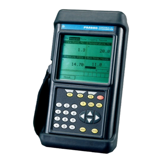
C h a p t e r 1 G e t t i n g S t a r t e d The GE Infrastructure Sensing PM880 is a versatile, battery- powered portable hygrometer that is designed for spot sampling moisture measurements. -
Page 11: Charging The Battery Pack
C h a r g i n g t h e B a t t e r y P a c k The PM880 is powered by a rechargeable NiMH battery pack. When you receive the PM880, you will need to fully charge the pack. The pack must be charged 4-5 hours until the amber LED on the charger goes out to receive the maximum charge. -
Page 12: Configuring The Battery Charger
C o n f i g u r i n g t h e B a t t e r y C h a r g e r The PM880 battery charger has a switchable voltage input of 115 to 230 VAC. Before you plug the pack into the charger you must make sure the voltage selector is in the correct position before plugging it in. -
Page 13: Charging The Battery Pack
4. Remove the pack from the charger and reinstall it in the PM880. Refer to Checking the Battery Status on page 8-4 for details on monitoring the battery. 1 - 4... -
Page 14: Powering On
P o w e r i n g O n To turn the PM880 on, press the red button in the upper-right- hand corner of the keypad. Immediately upon power up the PM880 displays a series of messages and performs various checks. -
Page 15: Powering Off
F e b r u a r y 2 0 0 5 P o w e r i n g O f f 1. To turn the PM880 off, press the red key for 3 seconds. The screen now appears similar to Figure 1-2 below. -
Page 16: Entering Setup Data
Use the sections that follow to program your meter. The PM880 has additional menus that enable you to tailor N o t e : measurements as specifically as possible to your particular application. - Page 17 F e b r u a r y 2 0 0 5 S e l e c t i n g P r o b e T y p e ( c o n t . ) 4. At Type, press to open the drop-down list of probe [ENTER] types.
-
Page 18: Entering Calibration Data
Calibration Data Sheets are usually packed inside the probe cases. Since the PM880 enables you to use more than one probe, the meter provides a place to enter the probe serial number to help you match the probes to the corresponding site files. - Page 19 You only need to enter calibration data for M and TF Series probes. The Moisture Image Series (MISP) probe stores all calibration data in its electronics module, and uploads it into the PM880 memory when needed. It is not necessary to enter calibration data for the N o t e :...
- Page 20 F e b r u a r y 2 0 0 5 E n t e r i n g M o i s t u r e C a l i b r a t i o n D a t a ( c o n t . ) 5.
- Page 21 F e b r u a r y 2 0 0 5 W h a t ’ s N e x t ? Do one of the following: • If the probe has a pressure transducer, proceed to step 3 in Entering Pressure Calibration Data on the next page.
- Page 22 F e b r u a r y 2 0 0 5 E n t e r i n g P r e s s u r e C a l i b r a t i o n D a t a To enter calibration data for the pressure transducer, you must list the zero and span range in mV (or FP) and psig.
- Page 23 F e b r u a r y 2 0 0 5 E n t e r i n g P r e s s u r e C a l i b r a t i o n D a t a ( c o n t . ) 8.
-
Page 24: Displaying Measurements
F e b r u a r y 2 0 0 5 D i s p l a y i n g M e a s u r e m e n t s The PM880 can display one to four measurement parameters simultaneously. There are two parts for displaying measurements: selecting the number of measurements and then selecting the type of measurements. - Page 25 F e b r u a r y 2 0 0 5 D i s p l a y i n g M e a s u r e m e n t s ( c o n t . ) S e l e c t i n g t h e T y p e s o f M e a s u r e m e n t s ( c o n t .
-
Page 26: Saving Data In A Site File
F e b r u a r y 2 0 0 5 S a v i n g D a t a i n a S i t e F i l e A site file contains probe ID, calibration data and display setup information into a file so it can be recalled at the measurement site. - Page 27 S a v i n g D a t a i n a S i t e F i l e ( c o n t . ) 2. The PM880 displays a default name for the file. If you want to keep the default name, skip to step 4.
- Page 28 F e b r u a r y 2 0 0 5 Menu Program Site Manager Save 1 View 2 Views 3 Views 4 Views Probe Calibrate MISP None File Hygro Pressure Probe ID Zero FP MH (FH) Hygro Constant Zero kPa Dew Point Temperature Constant...
-
Page 29: Installing The Probe Into A Sample System
C h a p t e r 2 T a k i n g M e a s u r e m e n t s The PM880 hygrometer is part of measurement system that consists of the electronics, cable, probe and optional sample system. - Page 30 F e b r u a r y 2 0 0 5 I n s t a l l i n g t h e P r o b e i n t o a S a m p l e S y s t e m Moisture probes are installed into a portable sample system.
- Page 31 F e b r u a r y 2 0 0 5 C o n n e c t i n g t h e S a m p l e S y s t e m t o t h e P r o c e s s To connect the sample system to the process at the measurement site, refer to Figure 2-1 below and complete the following steps:...
-
Page 32: Making Probe Connections
M a k i n g P r o b e C o n n e c t i o n s Use the following steps to make probe connections: 1. Make sure the PM880 is turned off. 2. Connect the cable to the probe by inserting the bayonet-type connector onto the probe and twisting the shell clockwise until it snaps into a locked position. -
Page 33: Recalling A Site File
5. Press (Exit). [F3] 6. Press . The PM880 displays the selected site file in the [MENU] upper-left of the screen. T a k i n g M e a s u r e m e n t s 2 - 5... -
Page 34: Operating The Sample System
6. Turn on the PM880. F i g u r e 2 - 3 : V a l v e L o c a t i o n s o n t h e S a m p l e S y s t e m... -
Page 35: Conducting A Leak Test
F e b r u a r y 2 0 0 5 C o n d u c t i n g a L e a k T e s t It is important to eliminate all leaks for safety reasons and to be sure that measurements are not affected by ambient contamination. -
Page 36: Screen Components
U s i n g t h e P M 8 8 0 S c r e e n Use the sections that follow to setup and make adjustments to the PM880 screen. This chapter discusses the following: • Screen Components - page 3-2 •... - Page 37 F e b r u a r y 2 0 0 5 S c r e e n C o m p o n e n t s The PM880 screen displays various information (see Figure 3-1 below). The top line of the screen is the status bar that displays the current site being used, time, date and battery status during normal operation.
- Page 38 F e b r u a r y 2 0 0 5 S c r e e n C o m p o n e n t s ( c o n t . ) T a b l e 3 - 1 : I c o n s i n t h e S y s t e m T r a y Icon Function Meaning...
-
Page 39: Selecting The Number Of Views (Measurements)
Adjusting the Line/Bar Graph Scale - page 3-7 Use the section(s) that follow to set up the PM880 screen. S e l e c t i n g t h e N u m b e r o f V i e w s ( M e a s u r e m e n t s ) 1. -
Page 40: Selecting Numeric, Line Or Bar Graph Format
[ENTER] 3. Use the arrow keys to select the desired format and press [ENTER] The PM880 displays the desired format and returns to taking measurements. Test Equipment Depot - 800.517.8431 - 99 Washington Street Melrose, MA 02176 FAX 781.665.0780 - TestEquipmentDepot.com... -
Page 41: Setting Up The Numeric Format
F e b r u a r y 2 0 0 5 S e t t i n g U p t h e N u m e r i c F o r m a t 1. Press to move the pointer to the window you want to [SEL] change and press [ENTER]... -
Page 42: Adjusting The Line/Bar Graph Scale
(OK). [F3] The PM880 displays the new format and returns to taking measurements. A d j u s t i n g t h e L i n e / B a r G r a p h S c a l e The scale of the line and bar graph can be adjusted at any time. - Page 43 (not currently available) 10.Press (OK). [F3] The PM880 displays the new format and returns to taking measurements. 3 - 8 U s i n g t h e P M 8 8 0 S c r e e n...
-
Page 44: Creating Function Key Shortcuts
C r e a t i n g F u n c t i o n K e y S h o r t c u t s The three function keys at the bottom of the PM880 screen can be customized to provide shortcuts to the most commonly used functions. -
Page 45: Clearing A Function Key
U s i n g t h e B a c k l i g h t The PM880 has a backlight that helps in viewing data. Since the backlight uses more energy, the PM880 has a backlight timer that you can set to automatically turn the backlight off after a specified time in order to conserve battery life. -
Page 46: Adjusting The Contrast
6. When you are done, press (OK). [F3] The PM880 returns to taking measurements. U s i n g t h e P M 8 8 0 S c r e e n 3 - 1 1... -
Page 47: Taking A Bitmap Screen Capture (Snapshot)
To Printer - to send the snapshot to the printer. • To File - to send the snapshot to a file. In order to send a screen capture to a printer, the PM880 N o t e : must be properly configured to IR transfer. Refer to Setting Up the PM880 IR Communications on page 7-2. - Page 48 ( S n a p s h o t ) 6. If you selected: • To Printer - the PM880 indicates it is looking for a receiving printer and then transmits the file. If the sensor cannot location a printer, a window appears N o t e : indicating that it cannot find a device.
-
Page 49: Selecting English Or Metric Units
U s i n g S p e c i a l F e a t u r e s The PM880 has a variety of other features to make operation even more convenient. Below is a list of some of the features available. - Page 50 S e l e c t i n g E n g l i s h o r M e t r i c U n i t s The PM880 enables you to select either English or Metric units as global measurement units.
-
Page 51: Changing Date And Time Appearance
F e b r u a r y 2 0 0 5 C h a n g i n g D a t e a n d T i m e A p p e a r a n c e In addition to setting the correct date and time, you can also change its presentation to suit local preferences. -
Page 52: Changing The Date And Time Appearance
(OK) and then press [F3] [MENU] The PM880 returns to taking measurements. The new date and time formats are displayed. 4 - 4 U s i n g S p e c i a l F e a t u r e s... -
Page 53: Adding A Message To A Site File
F e b r u a r y 2 0 0 5 A d d i n g a M e s s a g e t o a S i t e F i l e The Site Manager has a command that enables you to enter a message or description for each site file (up to 30 characters). -
Page 54: Setting A Probe Calibration Reminder
F e b r u a r y 2 0 0 5 S e t t i n g a P r o b e C a l i b r a t i o n R e m i n d e r The Probe ID command enables you to enter the probe serial number, calibration dates and a calibration reminder. - Page 55 7. Use the arrow keys to move to Cal Reminder and press . This prompt asks you to select a time period for the [ENTER] next probe calibration. The PM880 will display a calibration reminder for the probe determined from the last calibration date. GE Infrastructure Sensing recommends recalibrating a probe a minimum of once a year.
-
Page 56: Using Automatic Calibration (Auto-Cal)
U s i n g A u t o m a t i c C a l i b r a t i o n ( A u t o - C a l ) The PM880 automatically calibrates the moisture and pressure measurement circuitry (Auto-cal) at a user-selected interval. -
Page 57: Using Automatic Calibration
See the example below. EXAMPLE: The PM880 establishes a fixed schedule, beginning at midnight, using the interval specified to determine the times of subsequent Auto-cals. If you enter an 8 hour time interval, Auto-cal will occur 3 times per day (1 day = 1440 minutes/480 minutes = 3). -
Page 58: Entering Constants And User Functions
To extend programming capability, user functions enable you to program up to 8 mathematical equations. Additionally, the PM880 also enables you to enter up to 6 tables of non-linear or empirical data to support user function equations. This section consists of the following information: •... -
Page 59: Additional Data
F e b r u a r y 2 0 0 5 E n t e r i n g a C o n s t a n t M u l t i p l i e r ( c o n t . ) F i g u r e 4 - 4 : T h e S y s t e m C o n f i g u r a t i o n W i n d o w W h a t ’... - Page 60 E n t e r i n g a S a t u r a t i o n C o n s t a n t The PM880 requires a saturation constant in order to calculate in non aqueous liquids. If you do not know the saturation constants of the process liquid sample, contact GE Infrastructure Sensing.
- Page 61 F e b r u a r y 2 0 0 5 E n t e r i n g a S a t u r a t i o n C o n s t a n t ( c o n t . ) 7.
- Page 62 F e b r u a r y 2 0 0 5 E n t e r i n g U s e r F u n c t i o n s User functions enable you to program mathematical equations. You can use any parameter in the meter to calculate a different parameter.
- Page 63 F e b r u a r y 2 0 0 5 E n t e r i n g U s e r F u n c t i o n s ( c o n t . ) E n t e r i n g a L a b e l f o r t h e F u n c t i o n ( c o n t .
- Page 64 F e b r u a r y 2 0 0 5 E n t e r i n g U s e r F u n c t i o n s ( c o n t . ) E n t e r i n g t h e U n i t s The steps below describe how to create a units symbol (e.g.
- Page 65 (Check) to test the validity of the function. The [F2] PM880 displays either “OK” or a message such as “Syntax Error.” U s i n g S p e c i a l F e a t u r e s...
- Page 66 F e b r u a r y 2 0 0 5 E n t e r i n g U s e r F u n c t i o n s ( c o n t . ) E n t e r i n g a n E q u a t i o n ( c o n t .
- Page 67 S e t t i n g U p U s e r T a b l e s To support user-defined functions, the PM880 can hold up to 6 tables of non-linear or empirical data. Users can enter up to 21 X-Y pairs in each table.
- Page 68 F e b r u a r y 2 0 0 5 S e t t i n g U p U s e r T a b l e s ( c o n t . ) E n t e r i n g a L a b e l f o r t h e T a b l e 1.
- Page 69 F e b r u a r y 2 0 0 5 S e t t i n g U p U s e r T a b l e s ( c o n t . ) E d i t i n g t h e U s e r T a b l e 1.
-
Page 70: Using Computer Enhanced Response
F e b r u a r y 2 0 0 5 U s i n g C o m p u t e r E n h a n c e d R e s p o n s e Computer Enhanced Response (CER) uses a dynamic moisture calibration technique to extrapolate the moisture level to the end point when making measurements in abrupt “dry down”... - Page 71 NORM - no computer enhanced response • CER - enable computer enhanced response The PM880 has an additional option called Derivative N o t e : Fast Response (DEF). The T System and T Sensor options are only active when DEF is selected. This option is available in Service Mode only.
-
Page 72: Entering Reference Data
The references are factory calibration values. These values can be found on the label located inside the battery compartment. If instructed by GE Infrastructure Sensing to change these values, refer to the steps follows. 1. If the menu is not active, press [MENU] 2. - Page 73 [ENTER] open the text box. 6. Use the numeric keys to enter the value recorded on the back of the PM880 and press [ENTER] 7. Repeat steps 5 and 6 for the low reference value. W h a t ’ s N e x t ? Do one of the following: •...
-
Page 74: Using Sleep Mode
F i g u r e 4 - 1 3 : T h e S h u t d o w n M e n u R e s u m i n g O p e r a t i o n Tap the red power key. The PM880 powers on, performs an auto- cal and returns to exactly where you left it. -
Page 75: Displaying Meter Information
PCI number. 5. Press (Exit) and then press [F3] [MENU] The PM880 returns to taking measurements. U s i n g S p e c i a l F e a t u r e s 4 - 2 7... -
Page 76: Changing The Display Language
F e b r u a r y 2 0 0 5 C h a n g i n g t h e D i s p l a y L a n g u a g e The PM880 user program is available in several languages. To change the language: The PM880 defaults to US English. -
Page 77: Using On-Line Help
F e b r u a r y 2 0 0 5 U s i n g O n - L i n e H e l p The PM880 offers on-line help screens that contain descriptions and instructions for various topics. You can access on-line help at anytime by press the [?] key. -
Page 78: Setting Up A New Log
For example, a 2 hour log that records every 5 seconds will use up more memory than a 2 hour log that records every 5 minutes. The PM880 also has various tools to enable you to do the following: •... - Page 79 F e b r u a r y 2 0 0 5 S e t t i n g u p a N e w L o g Use the following steps to create a new log. If you need to create another log file that is similar to a N o t e : log you have already created, you can save time by copying the existing log and editing it.
- Page 80 F e b r u a r y 2 0 0 5 S e t t i n g u p a N e w L o g ( c o n t . ) E n t e r i n g a L o g N a m e 1.
- Page 81 F e b r u a r y 2 0 0 5 S e t t i n g u p a N e w L o g ( c o n t . ) S e l e c t i n g G e n e r a l L o g S e t t i n g s 1.
- Page 82 Log Manager, press (Exit) and [F3] then press [MENU] The PM880 returns to taking measurements. A Pencil icon appears in the bottom right-hand side of the screen. L o g g i n g D a t a 5 - 5...
-
Page 83: Pausing A Log
F e b r u a r y 2 0 0 5 P a u s i n g a L o g The PM880 has two commands to pause logs: Pause and Pause All Logs. The PM880 can only pause logs that are currently running. -
Page 84: Starting Or Restarting A Log
4. Use the arrow key to scroll to Start or Start All Logs and press [ENTER] The PM880 returns to the Log Manager, which displays the selected log as Running or Pending. W h a t ’ s N e x t ? Do one of the following: •... - Page 85 4. Use the arrow key to scroll to End or End All Logs and press [ENTER] The PM880 returns to the Log Manager, which displays the selected log as Finished. W h a t ’ s N e x t ? Do one of the following: •...
- Page 86 F e b r u a r y 2 0 0 5 V i e w i n g A l l L o g s Logs are associated with the site in use at the time the log is created (or run).
-
Page 87: Viewing All Logs
V i e w i n g L o g S e t u p D e t a i l s The PM880 enables you to view more than the log details shown in Log Manager. The Details command enables you to see the log status, date and time, length, interval, records types of measurements logged and service information. -
Page 88: Viewing Log Setup Details
F e b r u a r y 2 0 0 5 V i e w i n g L o g S e t u p D e t a i l s ( c o n t . ) F i g u r e 5 - 5 : T h e L o g D e t a i l s L o g g i n g D a t a 5 - 1 1... -
Page 89: Displaying Logged Data
D i s p l a y i n g L o g g e d D a t a The PM880 enables you to view logged data in a graph or spreadsheet format. Graphs and spreadsheets are setup in the Log Manager. - Page 90 F e b r u a r y 2 0 0 5 U s i n g t h e G r a p h F o r m a t ( c o n t . ) S e l e c t i n g a M e a s u r e m e n t P a r a m e t e r 1.
- Page 91 F e b r u a r y 2 0 0 5 U s i n g t h e G r a p h F o r m a t ( c o n t . ) A d j u s t i n g t h e G r a p h S c a l e 1.
- Page 92 F e b r u a r y 2 0 0 5 U s i n g t h e G r a p h F o r m a t ( c o n t . ) A d j u s t i n g t h e T i m e S c a l e 1.
-
Page 93: Using The Spreadsheet Format
F e b r u a r y 2 0 0 5 U s i n g t h e S p r e a d s h e e t F o r m a t 1. Use the arrow key to scroll to the desired log. Logs are associated with the site file in use at the time the log is created or run. - Page 94 3. Repeat steps 1 and 2 for other entries. 4. When you have finished, press (OK) to exit and view the [F3] spreadsheet. The PM880 displays the data nearest the time entered. W h a t ’ s N e x t ? Do one of the following: •...
- Page 95 Manager. The Site Manager enables you to create, recall, edit, rename and delete site files, the Drive Manager enables you to transfer and delete all types of files the PM880 can generate, while the Log Manager lets you rename, copy and delete log files.
-
Page 96: Saving A New Site File
F e b r u a r y 2 0 0 5 S a v i n g a N e w S i t e F i l e Use the steps below to save a new site. A c c e s s i n g t h e S i t e M a n a g e r 1. - Page 97 (OK). [F3] 5. The PM880 prompts asks you if you want to save the site as a template. Saving the site file as a template is useful when you need to create multiple sites with similar data. At the prompt, do one of the following: •...
- Page 98 (Yes). [F3] 6. Press (Exit). [F3] 7. Press . The PM880 displays the new site file in the [MENU] upper-left corner of the screen. 6 - 4 M a n a g i n g F i l e s...
- Page 99 2. Use the arrow keys to scroll to Site and press [ENTER] 3. Use the arrow keys to scroll to Save Now and press [ENTER] 4. The PM880 prompts you to save the current site, press [F3] (Yes). 5. Press .
- Page 100 6-8. R e n a m i n g a S i t e F i l e The PM880 offers two ways to rename files. In the Site Manager you can use the following commands: •...
-
Page 101: Recalling A Site File
7. When you have finished, press (OK). [F3] 8. Do one of the following: • If you selected Save As, the PM880 prompts you to save the current site, press (Yes) and proceed to What’s [F3] Next? below. •... -
Page 102: Renaming A Log File
7. When you have finished, press (OK). [F3] The PM880 renames the file and returns to the Log Manager. Proceed to What’s Next? below. W h a t ’ s N e x t ? Do one of the following: •... -
Page 103: Copying A Log
F e b r u a r y 2 0 0 5 C o p y i n g a L o g If you need to create another log file that is similar to a log you have already created, you can save time by copying the existing log and editing it. - Page 104 F e b r u a r y 2 0 0 5 C o p y i n g a L o g ( c o n t . ) F i g u r e 6 - 2 : N a m e E n t r y W i n d o w f o r a N e w L o g E n t e r i n g a L o g N a m e 1.
- Page 105 F e b r u a r y 2 0 0 5 C o p y i n g a L o g ( c o n t . ) E d i t i n g G e n e r a l L o g S e t t i n g s ( c o n t . ) 2.
- Page 106 5. When you have finished, press (Activate) to start the log. [F3] The PM880 returns to the Log Manager. The log will begin at the specified date and time. W h a t ’ s N e x t ? Do one of the following: •...
-
Page 107: Deleting All Types Of Files
F e b r u a r y 2 0 0 5 D e l e t i n g A l l T y p e s o f F i l e s Use the steps below to delete unwanted files from the PM880 memory:... - Page 108 F e b r u a r y 2 0 0 5 D e l e t i n g A l l T y p e s o f F i l e s ( c o n t . ) W h a t ’...
- Page 109 F e b r u a r y 2 0 0 5 S o r t i n g F i l e s i n t h e S i t e / D r i v e / L o g M a n a g e r The Site, Drive or Log Manager can list files in chronological or alphabetical order.
- Page 110 U s i n g t h e P M 8 8 0 w i t h a P C a n d P r i n t e r The PM880 has the ability to transfer files to and from a PC. The Site Manager and Drive Manager both have a transfer command that allows you to select a file and beam it to and from the PC and the PM880.
- Page 111 PM880 functions using your computer. Use the following steps if you need to change the PM880 IR set A c c e s s i n g t h e M e t e r M e n u 1.
- Page 112 T r a n s f e r r i n g a n d P r i n t i n g F i l e s K e y Since the PM880 offers many tools and options for file management, Table 7-1 breaks down each Manager and its transferring and printing capabilities.
-
Page 113: Setting Up Pm880 Ir Communications
3. Use the arrow key to scroll to Site and press [ENTER] 4. Make sure the IR beam on the PM880 has clear access to the IR sensor on the printer. 5. Use the arrow key to scroll to Print and press [ENTER] The PM880 indicates that it is searching for a receiving printer. -
Page 114: Printing A Site File (Cont.)
S e l e c t i n g a S i t e F i l e ( c o n t . ) 6. Once the PM880 finds the printer, it asks you to confirm, press (Yes) and then press . - Page 115 E n t e r i n g a T i m e W i n d o w f o r P r i n t i n g ( c o n t . ) 2. Make sure the IR beam on the PM880 has clear access to the IR sensor on the printer and press (OK).
-
Page 116: Printing Reports
F i g u r e 7 - 3 : T h e R e p o r t s W i n d o w 4. Use the arrow keys to select the desired report. 5. Make sure the IR beam on the PM880 has clear access to the IR sensor on the printer. -
Page 117: Transferring A File To A Pc
Manager to transfer files to your PC. The Site Manager allows you to transfer site files only; the Drive Manager enables you to transfer any file in the PM880; and, the Log Manager enables you to transfer log files only. - Page 118 For Drive or Log Manager - File and press [ENTER] 4. Make sure the IR beam on the PM880 has clear access to the IR sensor on the PC. 5. Use the arrow key to scroll to Transfer and press [ENTER] 6.
- Page 119 F e b r u a r y 2 0 0 5 T r a n s f e r r i n g a F i l e T o a P C ( c o n t . ) L o c a t i n g a n d V i e w i n g t h e T r a n s f e r r e d F i l e Your PC stores the transferred file in a default location.
-
Page 120: Transferring A File From A Pc
T r a n s f e r r i n g a F i l e f r o m a P C The PM880 enables you to transfer site (.sit) and meter (.met) files from your PC to the meter. If you rename another type of file with one of these extensions and transfer it, it will be transferred, but will not function if you open it. -
Page 121: Using Windows Nt 4.0
® 1. Open the QuickBeam software. 2. Make sure the IR beam on the PM880 has clear access to the IR sensor on the PC. 3. In the Quickbeam window, click on Send. 4. Click on Files or Files on Clipboard and scroll to the desired file. - Page 122 U s i n g W i n d o w s 2 0 0 0 1. To activate infrared communications on your PC, line up the IR beam on the PM880 with the PC’s IR sensor. A window appears indicating IR communications is activated.
- Page 123 T r o u b l e s h o o t i n g t h e P M 8 8 0 The PM880 is designed to be maintenance and trouble-free; however, because of process conditions and other factors, minor problems may occur.
-
Page 124: T R O U B L E S H O O T I N G T H E P M 8 8 0
While the MIS Probe and Factory Calibration options N o t e : appear on the Service Menu, they are only available to operators with a Service level security code. Consult GE Infrastructure Sensing for further information. 8 - 2... -
Page 125: Checking The Pm880 Memory Status
C h e c k i n g t h e P M 8 8 0 M e m o r y S t a t u s The PM880 stores all types of files in its memory. Each type of Manager enables you to monitor the size of a file and the remaining amount memory. -
Page 126: Checking The Battery Status
C h e c k i n g t h e B a t t e r y S t a t u s The PM880 provides two ways to monitor the battery status: displays a battery icon while taking measurements and using the Battery command. - Page 127 F e b r u a r y 2 0 0 5 U s i n g t h e B a t t e r y C o m m a n d ( c o n t . ) F i g u r e 8 - 1 : T h e B a t t e r y C h a r g e r W i n d o w M a i n t a i n i n g a n d T r o u b l e s h o o t i n g t h e P M 8 8 0 8 - 5...
-
Page 128: Testing The Screen
5. Press any key. The screen should redraw with the same checkerboard pattern. Make sure the screen redraws properly. 6. Keep pressing keys to change the screen. The PM880 will sequence through a number of dark and light screens before returning to taking measurements. -
Page 129: Testing The Keypad
[F3] [MENU] If any key does not appear on the screen, contact GE Infrastructure Sensing. M a i n t a i n i n g a n d T r o u b l e s h o o t i n g t h e P M 8 8 0... -
Page 130: Testing The Watchdog Timer Circuit
T e s t i n g t h e W a t c h d o g T i m e r C i r c u i t The PM880 includes a watchdog timer circuit. If a software error causes the meter to stop responding, this circuit automatically resets the meter. -
Page 131: Resetting To Factory Default Settings
R e s e t t i n g t o F a c t o r y D e f a u l t S e t t i n g s The Factory Defaults command enables you to return the meter to its preprogrammed default settings. The PM880 replaces the default site file and the global meter settings with the factory default settings. - Page 132 6. The program asks for confirmation: “Are you SURE?” Press (Yes). [F3] The PM880 replaces the default site file and the global meter settings with the factory default settings. When the meter returns to taking measurements, it displays data using the default site.
-
Page 133: Viewing Or Changing Security Settings
V i e w i n g o r C h a n g i n g S e c u r i t y S e t t i n g s To guard against accidental or intentional tampering, the PM880 includes a password-based security system. -
Page 134: Setting The Security Passcodes
F e b r u a r y 2 0 0 5 S e t t i n g t h e S e c u r i t y P a s s c o d e s To enter new security passcodes: 1. -
Page 135: Setting Remote Access Security
S e t t i n g R e m o t e A c c e s s S e c u r i t y The PM880 enables you to set remote access security for each security level. Remote access consists of allowing the PM880 to... - Page 136 S e t t i n g R e m o t e A c c e s s S e c u r i t y ( c o n t . ) 7. The PM880 may ask you to enter a passcode depending on the level you choose.
-
Page 137: Updating Pm880 Software
U p d a t i n g P M 8 8 0 S o f t w a r e As discussed in Chapter 7, Using the PM880 with a PC or Printer, the PM880 uses an IR transceiver to transfer files. The IR function can also be used to upgrade the meter’s user program. - Page 138 GE Infrastructure Sensing recommends updating software via the IrOBEX standard; however, the IrCOMM standard is available for users who have problems with IrOBEX. Use Table 8-2 below to find out which standard your PC’s operating system can use.
-
Page 139: Updating Software Via Irobex
8-19. U p d a t i n g S o f t w a r e v i a I r O B E X Use the sections below to upgrade the PM880 software using IrOBEX. S e t t i n g U p P M 8 8 0 1. - Page 140 (OK) to continue [F3] with the update. 6. After the PM880 reboots, the meter will ask you a series of questions. Use the appropriate function key to respond, then refer to the next section. D o w n l o a d i n g U s e r P r o g r a m U p g r a d e s...
-
Page 141: Updating Software Via Ircomm
(OK) to continue [F3] with the update. 6. After the PM880 reboots, the meter will ask you a series of questions. Use the appropriate function key to respond, then refer to the next section. M a i n t a i n i n g a n d T r o u b l e s h o o t i n g t h e P M 8 8 0... - Page 142 F e b r u a r y 2 0 0 5 S e t t i n g U p P M 8 8 0 ( c o n t . ) F i g u r e 8 - 9 : T h e F l a s h U p d a t e W i n d o w D o w n l o a d i n g U s e r P r o g r a m U p g r a d e s 1.
- Page 143 4. From the Protocol drop-down menu, select Xmodem. 5. Click Send. For a successful transfer, the PC window appears similar to Figure 8-11 below, while the PM880 screen displays the program ID, size, load address and a count of blocks being loaded.
-
Page 144: Removing/Replacing The Batteries
Recharging the Batteries on the next page. 2. Remove the four thumb screws on the back panel of the PM880 that secure the NiMH battery pack. Lift the battery pack out of the unit. See Figure 8-12 below. 3. Insert the new battery pack. -
Page 145: Recharging The Batteries
R e c h a r g i n g t h e B a t t e r i e s The PM880 is powered by a rechargeable NiMH battery pack. The batteries must be charged 4-5 hours until the amber LED on the charger goes out to receive the maximum charge. -
Page 146: Configuring The Battery Charger
C o n f i g u r i n g t h e B a t t e r y C h a r g e r The PM880 battery charger has a switchable voltage input of 115 to 230 VAC. Before you plug the pack into the charger you must make sure the voltage selector is in the correct position before plugging it in. -
Page 147: Charging The Battery Pack
4. Remove the pack from the charger and reinstall it in the PM880. Refer to Checking the Battery Status on page 8-4 for details on monitoring the battery. M a i n t a i n i n g a n d T r o u b l e s h o o t i n g t h e P M 8 8 0... -
Page 148: Error And Screen Messages
E r r o r a n d S c r e e n M e s s a g e s The PM880 has a series of error messages that display on the screen when the error occurs. The error messages are only general descriptions of the possible problems. - Page 149 Auto- Cal, or a probe fail- ure is interfering with AutoCal. Err 25: No Data The MIS Probe has The PM880 will try to not responded, or a send data; wait for next calculation is not yet update. complete.
-
Page 150: M A I N T A I N I N G A N D T R O U B L E S H O O T I N G T H E P M 8 8 0
[F3] No link to the MIS This screen appears Press ) to can- when trying to write cel all writes. The PM880 probe. to a disconnected will read from the next MIS probe. connected MIS probe. During the “No Link”... - Page 151 F e b r u a r y 2 0 0 5 T a b l e 8 - 3 : E r r o r a n d S c r e e n M e s s a g e s ( c o n t . ) E r r o r M e s s a g e P r o b l e m A c t i o n...
-
Page 152: Common Problems
F e b r u a r y 2 0 0 5 C o m m o n P r o b l e m s If the PM880 measurement readings seem strange, or they do not make sense, there may be a problem with the probe or a component of the process system. - Page 153 PM880. M a i n t a i n i n g a n d T r o u b l e s h o o t i n g t h e P M 8 8 0...
- Page 154 Improper cable Check the cable connections to both connection. the probe and the PM880. S y m p t o m : S l o w r e s p o n s e . Slow outgassing of Replace the system components with system.
-
Page 155: Replacing And Recalibrating The Moisture Probes
Contact a GE Infrastructure Sensing applications engineer for the recommended calibration frequency for your application. You can program the PM880 to remind you when it is time N o t e : to send the probes back for recalibration. Refer to Setting... -
Page 156: Recalibrating The Pressure Sensors
F e b r u a r y 2 0 0 5 R e c a l i b r a t i n g t h e P r e s s u r e S e n s o r s Since the pressure sensor on a TF or Moisture Image Series (MIS) Probe is a strain gage type, the pressure calibration is linear and is calibrated at 2 data points. -
Page 157: The Pm880 Hygrometer
T h e P M 8 8 0 H y g r o m e t e r The center of the measurement system is the PM880 hygrometer. The front of the meter has a Liquid Crystal Display, a membrane keypad and menu keys. -
Page 158: Probes
T h e P M 8 8 0 H y g r o m e t e r ( c o n t . ) The top of the PM880 (shown in Figure 9-2 below) includes an input for connecting moisture probes. An internal infrared... -
Page 159: M Series And Tf Series Moisture Probes
M S e r i e s a n d T F S e r i e s M o i s t u r e P r o b e s The M Series and the TF Series probes are very similar. Both probes use the GE Infrastructure Sensing aluminum oxide sensors to measure moisture, and a thermistor bead (optional) to measure temperature. -
Page 160: Moisture Image Series Probe
The M and the TF Series probes, when operated with a BASEEFA-approved PM880, are intrinsically safe and designed to meet the requirements of IEC/CENELEC zone 0 areas. The M and TF Series probes measure moisture content in a standard range from -110°C to 20°C (-166°F to 68°F) dew/frost... -
Page 161: Cabling
The M and the TF Series probes are connected to the analyzer with a special GE Infrastructure Sensing shielded cable. Probes can be located up to 600 meters (2,000 feet) from the PM880 (consult GE Infrastructure Sensing for distances up to 1,200 meters). -
Page 162: Overall
F e b r u a r y 2 0 0 5 O v e r a l l C h a n n e l s Single Channel D i m e n s i o n s Size: 9.4 × 5.5 × 1.5 in. •... - Page 163 E l e c t r o n i c s I n t e r n a l B a t t e r i e s Rechargeable. PM880 batteries can be installed or removed in hazardous areas. Batteries must be recharged in general-purpose areas only.
-
Page 164: Electronics
E l e c t r o n i c s ( c o n t . ) P r i n t e r / T e r m i n a l O u t p u t Infrared communications port C a b l e s Cable type dependent on probe type: M Series, TF Series, or... -
Page 165: Moisture Measurement
M o i s t u r e M e a s u r e m e n t C o m p a t i b i l i t y Compatible with all GE Infrastructure Sensing aluminum-oxide moisture probes: M Series, TF Series and Moisture Image Series. -
Page 166: Temperature Measurement
F e b r u a r y 2 0 0 5 T e m p e r a t u r e M e a s u r e m e n t Optional thermistor is available for all GE Infrastructure Sensing moisture probes. -
Page 167: Sample System
F e b r u a r y 2 0 0 5 S a m p l e S y s t e m Specifications for SS880A standard sample system, comprising an inlet needle valve, a built-in coalescing filter and sample cell with bypass needle valve and venting tube, a pressure gage (various ranges), and an outlet needle valve with venting tube. -
Page 168: Choosing A Measurement Site
These factors should be discussed with a GE Infrastructure Sensing applications engineer or field sales person by the time you receive the PM880. However, if you decide to add additional measurement sites, this section contains some basic guidelines for selecting a measurement site and constructing a sample system. - Page 169 The end cap should not be removed except upon advice from GE Infrastructure Sensing. The sensor has been designed to withstand normal shock and vibration. You should make sure that the active sensor surface is never touched or allowed to come into direct contact with foreign objects, since this may adversely affect performance.
- Page 170 C o n s i d e r a t i o n s ( c o n t . ) Observing these few simple precautions will result in a long and useful probe life. GE Infrastructure Sensing recommends that probe calibration be checked routinely, at 12-month intervals, or as recommended by our applications engineers for your particular application.
- Page 171 F e b r u a r y 2 0 0 5 M o i s t u r e / T e m p e r a t u r e P r o b e C o n s i d e r a t i o n s ( c o n t . ) d.
- Page 172 In general, you should use stainless steel material for all wetted parts. Contact the GE Infrastructure Sensing PCI Division at 1-800- 833-9438 (within the USA) or 781-899-2719 (outside the USA) for further instructions.
- Page 173 F e b r u a r y 2 0 0 5 S a m p l e S y s t e m G u i d e l i n e s ( c o n t . ) Sample Cell Sample...
- Page 174 F e b r u a r y 2 0 0 5 A p p e n d i x B M e n u M a p s This chapter includes menu maps of the PM880 program. Refer to the following: •...
- Page 175 F e b r u a r y 2 0 0 5 Menu Logging Site Program Meter Service Figure B-2 Figure B-3 Figure B-4 Figure B-5 Fkeys About Manager Save 1 View 2 View 3 View 4 View Clear Clear Clear Site File...
- Page 176 F e b r u a r y 2 0 0 5 Menu Logging Site Program Service Meter Figure B-1 Figure B-3 Figure B-5 Figure B-4 User Probe System Calibrate Functions AutoCal Interval K X PPMv MISP None Function Saturation Probe Hygro Pressure...
- Page 177 F e b r u a r y 2 0 0 5 Menu Logging Site Program Service Meter Figure B-1 Figure B-2 Figure B-5 Figure B-4 Snapshot User Tables Communications Date/Time Backlight Language Contrast Units Battery Locale Table Date Backlight Time Printer File...
- Page 178 F e b r u a r y 2 0 0 5 Menu Logging Site Program Service Meter Figure B-1 Figure B-2 Figure B-5 Figure B-3 Log Manager New Log Name Format Sort File View Linear Circular Date Type Name Details Graph Spreadsheet Standard Error...
- Page 179 F e b r u a r y 2 0 0 5 Menu Site Logging Program Meter Service Figure B-1 Figure B-2 Figure B-4 Figure B-3 Security Factory Factory Flash Reports Test References MIS Probe Settings Defaults Calibration Update (Factory Use (Factory Use Only) Only)
-
Page 180: Calibration Reminder
F e b r u a r y 2 0 0 5 I n d e x About Option......... . . 4-27 Accessories . - Page 181 F e b r u a r y 2 0 0 5 I n d e x ( c o n t . ) C (cont.) Checks Power Up ..........1-5 Clearing Function Key .
- Page 182 F e b r u a r y 2 0 0 5 I n d e x ( c o n t . ) Electrical Connections........2-4 Electronics Error Messages .
- Page 183 F e b r u a r y 2 0 0 5 I n d e x ( c o n t . ) Installation ..........2-4 Conducting a Leak Test.
- Page 184 F e b r u a r y 2 0 0 5 I n d e x ( c o n t . ) M Series Probe Cables ..........9-5 Description .
- Page 185 F e b r u a r y 2 0 0 5 I n d e x ( c o n t . ) Passcodes..........8-11 Passwords .
- Page 186 F e b r u a r y 2 0 0 5 I n d e x ( c o n t . ) Sample System Connecting to Process........2-3 Description of .
-
Page 187: Troubleshooting
F e b r u a r y 2 0 0 5 I n d e x ( c o n t . ) S (cont.) Snapshot ..........3-12 Soft Key see Function Key Software version . - Page 188 F e b r u a r y 2 0 0 5 I n d e x ( c o n t . ) Units Option ..........4-2 Updating Software.
- Page 189 G E I n f r a s t r u c t u r e D E C L A R A T I O N S e n s i n g C O N F O R M I T Y W e , P a n a m e t r i c s L i m i t e d S h a n n o n I n d u s t r i a l E s t a t e...
- Page 190 G E I n f r a s t r u c t u r e D E C L A R A T I O N S e n s i n g C O N F O R M I T E N o u s , P a n a m e t r i c s L i m i t e d S h a n n o n I n d u s t r i a l E s t a t e...
- Page 191 G E I n f r a s t r u c t u r e K O N F O R M I T Ä T S - S e n s i n g E R K L Ä R U N G W i r , P a n a m e t r i c s L i m i t e d S h a n n o n I n d u s t r i a l E s t a t e...
- Page 192 G E I n f r a s t r u c t u r e A T E X C O M P L I A N C E S e n s i n g W e , G E I n f r a s t r u c t u r e S e n s i n g , I n c .
- Page 193 U S A 1 1 0 0 T e c h n o l o g y P a r k D r i v e B i l l e r i c a , M A 0 1 8 2 1 - 4 1 1 1 W e b : w w w .