
Related Manuals for GE Precision 500D


Summary of Contents for GE Precision 500D
- Page 1 5184516-100 Rev. 5 Revision 5 Precision 500D R&F System Operator Manual Copyright © 2007 By General Electric Co. om 5184516-100 Rev. 5...
- Page 2 om 5184516-100 Rev. 5...
- Page 3 Updated Table 7-1, Items 6 and 8 to identify X-ray control unit depending upon date of manufacture. Added model numbers to Table 7-1 row 1(Overhead tube Collimator) and row 4 (Precision 500D R&F Table Collimator). Added note about radiopacity after table 7-12. Added ifnormation on collimator lamp replacement for model 5234954 in Chapter 8.
- Page 4 THIS PAGE INTENTIONALLY LEFT BLANK om 5184516-100 Rev. 5...
-
Page 5: Table Of Contents
Table of Contents CHAPTER 1 ABOUT THIS GUIDE SECTION 1 PURPOSE OF THIS GUIDE ..................1-1 SECTION 2 PREREQUISITE SKILLS ..................1-1 SECTION 3 SAFETY NOTICES ....................1-1 SECTION 4 DISPOSAL OF WASTE ................... 1-2 CHAPTER 2 SAFETY AND REGULATORY SECTION 1 INTRODUCTION ..................... - Page 6 5-13 - Compression Device .................. 2-26 5-14 - Myelographic Operation ................2-26 5-15 - Myelographic Boots (Optional) ..............2-27 5-16 - Cone Operation ..................2-27 5-17 - Lead Apron ....................2-27 5-18 - Emergency Stop Button ................2-28 5-19 - Grounding Kit ..................... 2-30 5-19-1 - Purpose ..................
- Page 7 2-3 - System Shutdown ..................4-1 2-4 - Emergency Stop and System Recovery ............4-2 2-5 - Emergency Stop Recovery ................4-2 2-6 - System Recovery ..................4-2 2-7 - Procedure for Tube Warm Up ..............4-2 2-8 - Bar Code Scanner Option ................4-2 2-9 - International Keyboard Option ..............
- Page 8 3-3-10 - Printer Destination ................ 5-55 3-3-11 - Auto Send Destination ..............5-56 3-3-12 - Images Tagged ................5-56 3-4 - Service User Interface / Effect on IUI ............5-56 3-4-1 - Dose Measurement ................ 5-56 3-4-2 - Pulsed Fluoro ................. 5-56 3-4-3 - DSA Package .................
- Page 9 6-2-2 - Mask Refresh During Multiple Image Display ........ 6-13 SECTION 7 IMAGE STACKING (AND MAX/MIN OPACIFICATION OPTION) ......6-14 SECTION 8 CONRAST / WINDOW ..................6-18 SECTION 9 BRIGHTNESS / LEVEL ..................6-19 SECTION 10 IMAGE INVERT ..................... 6-19 SECTION 11 DEFAULT ......................
- Page 10 2-3-3 - Auxiliary Digital Operator Console ..........7-23 2-4 - Digital Fluoro Presentation Operator Console ........... 7-25 2-5 - Digital Multi-Function OperatorControl Group ..........7-27 2-6 - Precision 500D Table Operator Controls and Displays ......7-30 SECTION 3 SYSTEM SPECIFICATIONS ................. 7-32 3-1 - Precision 500D Table Specifications ............
- Page 11 SECTION 2 AUTOMATIC COLLIMATOR ................... 8-9 2-1 - Locking lever ..................... 8-11 2-2 - Display on the Collimator ................8-11 2-3 - Bottom View of the Collimator ..............8-12 2-4 - Linear LASER Light Localizer ..............8-12 2-5 - Centering Cross ..................8-12 2-6 - Rear View of Collimator ................
- Page 12 7-2 - Product Dimensions ................. 9-11 7-3 - Crate Dimensions ..................9-11 7-4 - SG120 Specifications ................9-12 7-4-1 - Wall Stand “General” ..............9-12 7-4-2 - Wall Stand Bucky ................9-12 CHAPTER 10 SG–100 VERTICAL BUCKY STAND SECTION 1 INTRODUCTION ....................
- Page 13 4-1 - Power Line Requirements ................11-7 4-2 - X–Ray Interlock Systems ................11-8 CHAPTER 12 ACCESSORIES SECTION 1 TABLE ACESSORIES ................... 12-1 1-1 - Patient Step ....................12-1 1-2 - Foot Rest ....................12-2 SECTION 2 OPTIONAL TABLE ACCESSORIES ..............12-3 2-1 - Shoulder Rest ....................
- Page 14 8-5 - 12.5° (218 mRad) 3ø, Low Speed, 60 Hz, 3400 rpm ......... A-12 8-6 - 12.5° (218 mRad) 3ø, Low Speed, 50 Hz, 2850 rpm ......... A-13 8-7 - 12.5° (218 mRad) 3ø, Low Speed, 60 Hz, 3400 rpm ......... A-14 8-8 - 12.5°...
- Page 15 SECTION 3 ABBREVATIONS .....................C-7 CHAPTER D MODES OF OPERATION SECTION 1 FLUOROSCOPY MODE ..................D-1 1-1 - Description ....................D-1 1-2 - System controlled technique factors ............D-1 1-3 - How to engage/ disengage ................D-1 1-4 - How to recognize when this mode is selected ..........D-2 1-5 - Example of specific clinical procedures ............D-3 1-6 - How mode should be used ................D-3 SECTION 2...
- Page 16 om 5184516-100 Rev. 5...
-
Page 17: About This Guide
CHAPTER 1 ABOUT THIS GUIDE SECTION 1 PURPOSE OF THIS GUIDE This guide is written for health care professionals (namely, X–Ray technologists) to provide the necessary information relating to the proper operation of the sys- tem. The guide is intended to teach you the system components and features necessary to use it to its maximum potential. -
Page 18: Disposal Of Waste
NOTE: A Note provides additional information that is helpful to you. It may emphasize certain information regarding special tools or techniques, items to check before proceeding, or factors to consider about a concept or task. SECTION 4 DISPOSAL OF WASTE This symbol indicates that the waste of electrical and electronic equipment must not be disposed as unsorted municipal waste and must be collected sepa- rately. -
Page 19: Safety And Regulatory
AMERICAS W–622 P.O. BOX 414 MILWAUKEE, WI 53201–0414 INDICATIONS FOR USE The Precision 500D R&F X–ray System is indicated for use in generating radio- graphic and fluoroscopic images of human anatomy in all general purpose X–ray diagnostic procedures. SECTION 2 WHAT DO I NEED TO KNOW ABOUT . -
Page 20: Patient Positioning And Control
– Electrical Safety – Patient Positioning and Control – Table Angulation – Unsafe Table Region – Patient Grasp Handles – Safety Harness – Reciprocating Bucky – Bucky Grids – Patient Step – Foot Rest – Shoulder Rest – Compression Device –... - Page 21 Medical personnel. The products involved (and the accompanying electrical installations) are highly sophisticated, and special engineering competence is required. In performing all electrical work on these products, GE will use its own specially trained field engineers. All of GE’s electrical work on these products will comply with the requirements of the applicable electrical codes.
- Page 22 Call Traffic and Transportation, Milwaukee, WI (414) 827–3449 / 8*285–3449 immediately after damage is found. At this time be ready to supply name of car- rier, delivery date, consignee name, freight or express bill number, item damaged and extent of damage. Complete instructions regarding claim procedure are found in Section “S”...
- Page 23 The medical staff in charge of this equipment is required to instruct technicians, patients, and other people who may be around this equipment to fully comply with the above requirement. High levels of Radio Frequency (RF) energy in the vicinity of this X– Ray Suite may cause noise to appear on video monitors and recorders.
- Page 24 RADIATION SURVEY 4-1Introduction This report describes measurements of the distribution of stray radiation around the GE Precision 500D R & F unit. These measurements were made as specified in IEC 60601. 4-2Materials and Methods The reference point for all measurements was chosen as the center of the table- top with the table positioned horizontally, using its centering function.
- Page 25 fourth configuration was with the table in the 20º Trendelenberg position. The lead curtain was also removed in this case. Measurements of air kerma were made using a 500 ml ionization chamber con- nected to a Capintec electrometer. The chamber was mounted vertically on a tri- pod, centered at heights of 1.0 and 1.5 meters above the floor.
- Page 26 om 5184516-100 Rev. 5...
- Page 27 om 5184516-100 Rev. 5...
- Page 28 om 5184516-100 Rev. 5 2-10...
- Page 29 om 5184516-100 Rev. 5 2-11...
- Page 30 om 5184516-100 Rev. 5 2-12...
- Page 31 om 5184516-100 Rev. 5 2-13...
- Page 32 om 5184516-100 Rev. 5 2-14...
- Page 33 om 5184516-100 Rev. 5 2-15...
- Page 34 SECTION 5 SAFETY 5-1General Precautions Be alert to safety when operating this equipment. Be familiar enough with the equip- ment to recognize any malfunctions that can be a hazard. Do not use this equip- ment, if a malfunction occurs, until qualified service personnel correct the problem. Use proper technique factors for each procedure to minimize x-ray exposure and to produce the best diagnostic results.
- Page 35 Satisfactory equipment performance requires the use of service personnel specially trained on x–ray apparatus. GE Medical Systems is responsible for the effects on safety, reliability, and performance only if the following conditions are met: • The electrical wiring of the relevant rooms complies with the Regulations for the electrical equipment of buildings published by the Institution of Electrical Engineers as well as all national and local codes.
- Page 36 Always be alert to safety when you operate this equipment. You must be familiar enough with the equipment to recognize any malfunctions that can be a hazard. If a malfunction occurs or a safety problem is known to exist, do not use this equipment until qualified personnel correct the problem.
- Page 37 OPERATIONAL CHECKS Be sure the equipment is functioning properly and safely before each exam- ination: Verify that the following controls are operating correctly: • Motion Controls, and Lock Releases. • Audible and visual alarms. Visually inspect the equipment and make sure that: •...
- Page 38 KNOW THE EQUIPMENT Read and understand all the instructions in the operating manuals before attempt- ing to use the product and request training assistance from GE Medical System if needed. Keep operating manuals with the equipment at all times and periodically review the procedures and safety precautions.
- Page 39 1. Center the table top. If full table motion is not available, then 2. Move the table into the horizontal position. If full table motion is still not available. 3. Remove patient from table, safely, and call GE Service. om 5184516-100 Rev. 5...
- Page 40 Injury could occur from unintended motion. Remove patient from the table and call Service. 5-6Patient Grasp Handles The Patient Grasp handles may be engaged anywhere along the table top frame. Place the clamp fully onto the top frame and tighten the knob firmly. Instruct patients to use them.
-
Page 41: Travel And Counterbalancing
5-9Bucky Grids Grid choice is made at the time the equipment is ordered. Changing grids is not a normal user operation. Call GE Service to perform this service. 5-9-1 Oscillating Grid The Bucky grid oscillates during the X–ray exposure. X-ray exposures are pre- vented until the grid is in motion. -
Page 42: Patient Step
5-10Patient Step The patient step (ILLUSTRATION 2-2) provides patient convenience getting on and off the table. The step is attached to the underside of the table body to the right of the front support. Table angulation is prevented when the step is pulled out. -
Page 43: Foot Rest
The safety latches will reset to prevent accidental spreading of the handles. Check that BOTH handles have positive engagement by pulling on the foot rest. In case of any difficulties or doubts about the foot rest condition, call a qualified technician. - Page 44 5-13Compression Device The compression device is not intended to be used for patient support or restraint. It may be engaged at any point along the table top and consists of the front bracket with ratchet, roller and band, and the rear anchor bracket. To use: 1.
- Page 45 ILLUSTRATION 2-6 MYELOGRAPHIC STOP 5-15Myelographic Boots (Optional) These boots are intended for patient’s support during myelography and are attached to slots in the standard foot rest. When using these boots, mount the shoulder rest to the table for added safety assurance. THE SHOULDER REST NEED NOT BE IN ACTUAL CONTACT WITH THE PATIENT.
-
Page 46: Lead Apron
THE LEAD APRON PROTECTS THE OPERATOR FROM ANY SCATTER RADIATION. IT SHOULD REMAIN ATTACHED TO THE IMAGING DEVICE AT ALL TIMES. THIS LEAD APRON MUST BE INSTALLED IN ORDER TO MEET THE RADIATION PROTECTION REQUIREMENTS OF IEC 601–1–3. THIS LEAD APRON IS PART OF THE PRIMARY PROTECTIVE SHIELDING OF THE EQUIPMENT USED TO ATTENUATE THE RESIDUAL RADIATION FOR THE PROTECTION OF THE OPERATOR AND STAFF. -
Page 47: Emergency Stop Button
ILLUSTRATION 2-8 EMERGENCY STOP BUTTON IT IS EXTREMELY IMPORTANT TO CHECK THE OPERATION OF THIS BUTTON BEFORE EACH USE. THE PATIENT MUST NOT BE ADMITTED UNLESS THIS SAFETY FEATURE IS OPERATIONAL. om 5184516-100 Rev. 5 2-29... -
Page 48: Grounding Kit
5-19-2 Description The grounding outlet panel is located on the Precision 500D table base. This panel has connections for grounding the Precision 500D table top and other equipment such as a film changer and injector. The panel has four green ground- ing receptacles that accept grounding cord locking plugs. -
Page 49: Safety Summary
GE Medical Systems assumes no liability for the customer’s failure to comply. - Page 50 Do not attempt to alter any hardware unless the procedure is given in the Preventive/Corrective manual, or supplied with a part provided by GE Medical Systems. Doing so could disrupt the functioning of the system and result in loss of images.
- Page 51 Under certain conditions, transients on the power line may cause temporary anomalies to be present on the image monitors. This is a temporary degradation during the transient event and does not cause any system issues. om 5184516-100 Rev. 5 2-33...
- Page 52 THIS PAGE INTENTIONALLY LEFT BLANK om 5184516-100 Rev. 5 2-34...
-
Page 53: About The P500D
ABOUT THE P500D SECTION 1 INTRODUCTION The Precision 500D is a high resolution, PC–based, digital imaging system designed for Digital Videofluorography (DVF). It is designed to replace conven- tional fluoroscopic photospot film techniques. The system allows you to view 1024 x 1024 matrix images upon acquisition on a high resolution Image Monitor. -
Page 54: Options
Spot (subtracted and non–subtracted), fluoro and Digital Stepping images are acquired and stored in RAM (Random Access Memory). As the RAM memory fills the images are stored to the system’s hard disk. The relative space available for storing images is shown on the Image Monitor during all operating modes. An optional feature allows the last acquired Fluoro image of a fluoro sequence to be stored automatically to the system’s hard disk. -
Page 55: Power Up/Power Down
This option requires modification to the digital system Parameters set- tings. The keyboard must be installed by trained Service personnel. DONOT plug in any Keyboard unless it is supplied or approved by GE Medical Sys- tems. DICOM Images: Sending or Archiving images using the DICOM protocol will include the native language text;... - Page 56 Several features are controlled via the Image Monitor. Each Monitor screen is divided into two areas: the left side is dedicated to image selection and features controls, and the right side shows the image display and a few feature controls (see ILLUSTRATION 3-1).
-
Page 57: Mouse
6-1Keyboard The PC style keyboard is necessary for some modes of operation of the system. • The alphanumeric keys are used to enter patient and doctor information, enter run sequence titles, and annotation messages. Each system includes a Keyboard as a standard component. The main Keyboard is normally located in the control room. - Page 58 Table 4: RCIM controls Control Description 1. Emergency Stop Immediately powers down the system (including table, button OTS, wallstand, and x-ray tubes) and stops image expo- sure. • To engage: Press the button. • To release: Turn the button clockwise (indicated by the arrows on the button) until it stops, then release.
-
Page 59: X-Ray Tube Selection
Control Description 8. Collimator field Turns the collimator field light on or off. light button 9. Volume control Adjusts the volume of the system beeps. buttons SECTION 7 X-RAY TUBE SELECTION 7-1X-ray tube 1 For fluorography examinations, x-ray tube 1 is selected (under table x-ray tube). ILLUSTRATION 3-3 Tube1 “Selected”... - Page 60 When x-ray tube 1 is not selected, the IDD console appears as follows: ILLUSTRATION 3-4 Tube1 “Not Selected” 7-2X-ray tube 2 For radiography examinations, x-ray tube 2 is selected (over table x-ray tube). The Overhead Tube Suspension (OTS) user interface displays the following typi- cal information: ILLUSTRATION 3-5 Tube2 Selected om 5184516-100 Rev.
- Page 61 When x-ray tube 2 is not selected, the Overhead Tube Suspension (OTS) user interface console appears as follows: ILLUSTRATION 3-6 Tube2 “Not Selected” om 5184516-100 Rev. 5...
- Page 62 THIS PAGE INTENTIONALLY LEFT BLANK om 5184516-100 Rev. 5 3-10...
-
Page 63: Getting Started
Before you are able to begin making X–ray exposures, you need to start up the system. Press the “Power On” button located on the left side of the RCIM. The Precision 500D system was designed to be fully serviceable from the IUI control console. -
Page 64: Procedure For Tube Warm Up
2-4Emergency Stop and System Recovery Your system has a large red Emergency Stop button at an accessible location in your imaging facility. This button removes all power from the system. The Emer- gency Stop button or circuit breaker should be used for emergencies only. PRESS THE EMERGENCY STOP BUTTON ANYTIME THERE IS AN EMERGENCY CONDITION. -
Page 65: International Keyboard Option
During DICOM Worklist mode, using the bar code scanner makes loading manual queries easier. 2-9International Keyboard Option The digital system supports English and German language keyboard styles. om 5184516-100 Rev. 5... - Page 66 THIS PAGE INTENTIONALLY LEFT BLANK om 5184516-100 Rev. 5...
-
Page 67: Integrated User Interface
CHAPTER 5 INTEGRATED USER INTERFACE SECTION 1 INTRODUCTION The purpose of this chapter explains the functionality of the integrated user inter- face. This will be the first screen to appear on completion of the power boot–up. 1-1Power–on ILLUSTRATION 5-1 PATIENTS SCREEN om 5184516-100 Rev. - Page 68 The Digital Image screen displays a Patient List Screen after boot up. For an explanation of the functionality of this screen, refer to Chapter 6, Section ILLUSTRATION 5-2 PATIENT LIST SCREEN Depending on system configuration, the exam room monitor is blanked whenever the patient list is displayed (for patient privacy).
-
Page 69: Tube Warm-Up Screen
1-2Tube Warm–Up Screen NOTE: IMPORTANT! A tube warm–up should be performed if the unit has not made an exposure in two hours. This function will help extend the tube life. The Warm Tube button will appear when a warm–up is required. Select the Warm Tube button located on the lower right of the screen as shown in ILLUSTRATION 5-3. - Page 70 When performing a tube warm-up procedure for the under table or over table x-ray tube, the operator must remember that a tube warm up procedure produces a series of exposures and therefore produces a small amount of scatter radiation even though the collimator blades are at their minimum open position.
-
Page 71: Add/Select Patient Screen
Follow precautionary measures, do not perform Tube Warm–Up with patient(s) or personnel in the exam room. NOTE: At completion of Tube warm-up procedure, the user will return to the last Tube Warm-up screen viewed before the Tube Warm-up test was selected. ILLUSTRATION 5-4 PATIENT SCREEN The following tabs, located across the top of the screen, are selected from the... - Page 72 Patient List tab button selections: • Add Patient: This function places additional patients into the system. A dialog screen appears on the Digital Image Monitor which prompts the operator for pertinent patient information. See ILLUSTRATION 5-6. ILLUSTRATION 5-5 PATIENT LIST SCREEN The digital monitor displays a dialog box to input patient information.
- Page 73 NOTE: Patient List Screen will only accept a maximum of 44 characters for the first, mid- dle and last names combined. If the first, last and middle names combined exceeds 44 characters; the field will be truncated to 44 characters. The same rule applies to entering the Physician’s name.
-
Page 74: Start Exam
ILLUSTRATION 5-7 COLUMN DESCRIPTIONS STATUS COLUMN SERIES COLUMN IMAGES COLUMN SECTION 2 START EXAM 2-1Start Exam Scenario A patient can be selected from the worklist or an existing patient from the patient list. In this example, HIS/RIS is available and the patient is registered for a proce- dure. - Page 75 ILLUSTRATION 5-8 PATIENT SCREEN WORK LIST TAB om 5184516-100 Rev. 5...
-
Page 76: Start Exam Scenario
A Patient Work List appears on the Digital Image Screen. Select a registered patient for an image acquisition. ILLUSTRATION 5-9 DIGITAL MONITOR WORKLIST SCREEN Select Start Exam from the IUI Console. Refer to ILLUSTRATION 5-10. ILLUSTRATION 5-10 IUI WORKLIST SCREEN START EXAM BUTTON om 5184516-100 Rev. - Page 77 ILLUSTRATION 5-11 SELECT PROTOCOLS SCREEN (1) This screen will display the patient’s name selected for acquisition. By pressing the Select Protocols button, you will be able to choose an anatomical category. No patient name will appear if cassette only has been selected. Image Monitor screen will display a blank screen except for the “Site Name”.
- Page 78 After the major category is selected, protocols will be displayed as in the next screen. ILLUSTRATION 5-12 SELECT PROTOCOLS SCREEN (2) Select the procedure you wish to perform and press Accept. Multiple procedures from different categories may be selected before pressing Accept.
- Page 79 Acquisition screens have patient identification, procedure selected, technical fac- tors and receptors (table bucky, digital, etc. appropriate for your system). NOTE: The “Select Protocols” button located in the lower left of the IUI screen returns to the Select Protocols screen. See ILLUSTRATION 5-12.
- Page 80 Focal Spot There are two focal spot selections small 0.6 and large 1.25. Total Dose Total skin dose to patient for entire exam (fluoro and record images). Total DAP DOSE x AREA EXPOSED = PRODUCT (total area exposed during exam) Ion Chambers/AEC cells By pressing the Ion Chamber button, it will display all available combinations.
-
Page 81: Fluoro Acquisition Screen
2-2Fluoro Acquisition Screen ILLUSTRATION 5-15 FLUORO ACQUISITION SCREEN Selections • This screen will display record factors as well as fluoro factors. • The top portion of the screen is dedicated for record factors. • You may change your contrast type for the trajectories to compensate techni- cal parameters. - Page 82 ILLUSTRATION 5-16 MODIFIED PROTOCOL MODIFIED PROTOCOL If button is selected, it will revert to the existing protocols in the database. If a change is made to a stored protocol it will be noted as Modified on the screen. om 5184516-100 Rev. 5 5-16...
-
Page 83: Angio Acquisition Screen (Option)
2-3Angio Acquisition Screen (Option) ILLUSTRATION 5-17 ANGIO ACQUISITION SCREEN Pediatric Dose Selection (optional) provides specialized image acquisition param- eters for small pediatric patients. This special purchase option provides dedicated and tailored dose trajectories for infants and small children. •The dose can be limited to one of three rates: the standard 10 R/minute grid in or 5R/minute input dose (grid in or out). -
Page 84: Video Presentation
The Image Monitor will display the following screen: ILLUSTRATION 5-18 IMAGE MONITOR SCREEN 2-4Video Presentation These selections will change image presentation head/foot and left/right. 2-5Fluoro Time Total fluoro time is displayed. The 5 minute fluoro timer can be rest by pressing the button. An audible alarm will sound at the completion of 5 minutes. -
Page 85: View/Film
2-6View/Film This is utilized at the completion of an exam for filming and/or networking or dur- ing an exam to review all images in the series for possible additional films. ILLUSTRATION 5-19 VIEW/FILM SCREEN This symbol indicates the image has been tagged. Touch the desired number frame to Tag 1 Prior/Next Image 2 Prior/Next Page 3 Prior/Next Series... -
Page 86: Filming
2-7Filming The filming options are displayed to the right of the screen. Batch Filming This will display the selected film format, the number of images tagged for filming and the number of films required for this job. You may choose to film the entire study or only tagged images with the selector buttons Film All or Film Tagged. -
Page 87: Radiographic Exposure / Review Multitasking
Mark Study as Complete After the completion of an examination the close button is pressed. A pop up dia- log box appears which asks the operator if the study should be marked as com- plete. If “Yes” is selected an “F” is placed in the Status column in the Patient List screen and the file is locked. -
Page 88: Archive To Local Cd-Rw (Option)
This feature allows Radiographic Overtable exposures while reviewing digital record series. • Select a digital record protocol which has a radiographic protocol step. • Acquire digital record exposures. • Select the radiographic protocol step and review/modify the techic as needed. •... - Page 89 ILLUSTRATION 5-22 AUTO ARCHIVE CDRW STATUS COLUMN SERIES COLUMN IMAGES COLUMN SELECT THE ARCHIVE TO LOCAL CD–RW BUTTON om 5184516-100 Rev. 5 5-23...
-
Page 90: Emergency Recovery
2-10Emergency Recovery If during a procedure power is lost to the system, the system will reboot if power is returned to the unit after 30 seconds. NOTE: Upon reboot, the system will remember all patient parameters if power was lost during a procedure. -
Page 91: Edit Protocols
SECTION 3 EDIT PROTOCOLS 3-1Protocol Editor The Protocol Editor is entered by selecting the Protocols tab at the left of the Utili- ties screen. The Protocol Editor is a tool for the creation, modification, and dele- tion of Protocol Categories and Protocols. ILLUSTRATION 5-24 PROTOCOL EDITOR SCREEN If access to the Protocol Editor is denied, the Protocol Editor will display a pop–... -
Page 92: Protocol Editor
ILLUSTRATION 5-25 PROTOCOL EDITOR Select Protocols, then Edit to add protocols to your system or to modify an exist- ing one. After adjustments have been made and the data for the protocols saved. The total protocol data can be archived to CD by selecting Backup. (It is always advisable to maintain a record of data and changes as a backup file.) If data is lost, insert the backup CD and select Retrieve. -
Page 93: Protocols
The protocol database file is stored in the same location on the system as the other system log files. When loading the default protocols the user must select the correct Protocol CD-Rom. The system will warn the user that specific protocols have had modifications made to them. -
Page 94: Parameters For Tube 2 (Rad) Protocol Step
defined by the user for fluoro are: FOV, Horizontal Sweep, Vertical Sweep, Fluoro Frame Rate, and ROI. Technique specification for both fluoro and digital record should be made with the grid in the beam. The default digital record technique is: –... -
Page 95: Protocol Categories
3-2-3 Protocol Categories Add Category When Add Category is selected, the pop–up window appears as shown below: ILLUSTRATION 5-27 ADD CATEGORY User must touch this box to enter a Category Name The user is able to name the new Protocol Category. The length of the name is limited to 12 characters. - Page 96 ILLUSTRATION 5-28 ADD CATEGORY SCREEN Edit Category When Edit Category is selected, a pop–up window appears as shown below: ILLUSTRATION 5-29 EDIT CATEGORY The currently selected Protocol Category appears and the user is able to change the name, it’s position, or both. om 5184516-100 Rev.
-
Page 97: Protocols
To change position of a category, select the drop down menu and select the Pro- tocol category to be moved. A Protocol category can be positioned first or at any other position within the complete list of Protocol categories. NOTE: It is necessary to SAVE after changes have been made. - Page 98 Edit Protocol When Edit Protocol is selected, a pop–up window appears. The pop–up window is identical to the Add Protocol window. The name of the currently selected Protocol appears and the user is able to change it. The current default Patient Size appears and the user is able to change it.
- Page 99 Copy Protocol When Copy Protocol is selected, a pop–up window appears as shown below: ILLUSTRATION 5-32 COPY PROTOCOL The text “Default Patient Size” is included after the patient size icon to clarify what the field is for. The text “Position (After)” is included after the location drop down to clarify what the field is for.
- Page 100 When the user selects Cancel, the pop–up window closes. The Copy Protocol button is grayed out / inactive when no Protocol has been selected or 16 protocols exist for the current category. Delete Protocol When Delete Protocol is selected, a pop–up window appears. The name of the currently selected Protocol appears.
- Page 101 Add Protocol When Add Protocol is selected, a pop–up window appears as shown below: ILLUSTRATION 5-34 ADD PROTOCOL The user is able to name the new Protocol. Select the box in order to enter the Protocol name. The length of the name is limited to 12 characters. Select Patient Size for Patient Default size.
- Page 102 ILLUSTRATION 5-35 ADD PROTOCOL SCREEN After the new protocol has been added, Protocol Steps must be selected. om 5184516-100 Rev. 5 5-36...
- Page 103 Protocol Steps Button An Edit Steps button is provided at the bottom of the main screen. When no proto- cols are selected the button is grayed out. When a protocol is selected the button becomes available and will no longer be grayed out. When the Edit Steps button is selected, the Protocol Steps screen appears.
-
Page 104: Protocol Steps
3-2-5 Protocol Steps Add Step When Add Step is selected, a pop–up window appears. After Add Step is selected, the step must be named and the tube selected. ILLUSTRATION 5-38 NAMING THE STEP AND SELECTING THE TUBE The user is able to name the new Protocol Step. The length of the name is limited to 10 characters. - Page 105 The “OK” button will be grayed out/inactive until valid entries have been made. ILLUSTRATION 5-39 TUBE 1 EDIT om 5184516-100 Rev. 5 5-39...
- Page 106 Tube 2 Add Step NOTE: When building and modifying steps in your Protocols, it is important to remember your Protocol routine and the order the steps are placed in the Protocol. As a ben- efit, the Tube Bucky button on the IDD will move in descending order through the Tube 2 steps.
- Page 107 ILLUSTRATION 5-41 TUBE 1 EDIT To add an Angio Step, select Tube 1 and Angio instead of AEC. om 5184516-100 Rev. 5 5-41...
- Page 108 ILLUSTRATION 5-42 ANGIO STEP • The difference between AEC and Angio: with AEC the exposure factures are adjusted per each image in a multiple frame series. With an Angio multiple frame acquisition, the system will adjust the technical factors at the start of the series and after the adjustment, maintains it as a fixed technique for the com- pletion of the series.
- Page 109 When Tube 2 and OK have been selected on the Add Step screen, a pop–up win- dow appears as shown below: ILLUSTRATION 5-43 ADD STEP SCREEN The user is able to set the available Patient Sizes. The default Patient Size that was chosen at the Protocol level is checked and indicated with a star.
- Page 110 Tube 2 Technique Edit Review When a Tube 2 Protocol Step has been selected, the screen appears as shown below: All combinations of the previously selected Patient Size, Receptor, and AEC / Fixed appears down the left side of the table. The default technique now is indicated with a star just to the left of its Patient Size.
- Page 111 Tube 2 Technique Edit After selecting the “Edit Tech” button, the selected technique (row) will be shown in the upper left of the main area. For each technique the user will be able to adjust the following values. Film Speed / Screen (AEC only) Spectral Filter Ion Chamber (AEC only) Focal Spot...
- Page 112 Tube 1 Technique Edit When a Tube 1 Protocol Step has been selected, the screen appears as shown below: ILLUSTRATION 5-45 TUBE 1 PROTOCOL STEP SCREEN All of the record technique parameters appears above the top row of the table. All of the fluoro technique parameters appears above the bottom row of the table.
- Page 113 Common Controls for Tube 1 and Tube 2 The name of the Protocol appears as text above the column of Protocol Step buttons on the left side of the work space. Edit Step When Edit Step is selected, a pop–up window appears. ILLUSTRATION 5-46 EDIT STEP om 5184516-100 Rev.
- Page 114 Tube 2 Edit Step ILLUSTRATION 5-47 TUBE 2 EDIT STEP SCREEN When the user selects either Tube 1 or Tube 2 and OK, the screen changes to the Tube 2 Edit Step screen. • The user is able to select “OK” without making any changes. •...
- Page 115 Copy Setup When Copy Step is selected a pop–up window appears as shown below: ILLUSTRATION 5-48 COPY STEP The user is able to name the new Protocol Step. The length of the name is limited to 10 characters. When the user selects OK, the screen changes to the Technique Edit screen for the new Protocol Step.
- Page 116 Delete Setup When Delete Step is selected, a pop–up window appears. ILLUSTRATION 5-49 DELETE STEP The name of the currently selected Protocol Step appears. When the user selects Delete, the selected Protocol Step button disappears and the Add Step button moves up one slot. om 5184516-100 Rev.
- Page 117 Save When Save is selected a pop–up window appears as shown below: ILLUSTRATION 5-50 SAVE POP-UP WINDOW When the user selects Save the protocol database is updated with any additions and changes. Cancel When Cancel is selected a pop–up window appears as shown below: ILLUSTRATION 5-51 CANCEL POP-UP WINDOW When the user selects YES, the screen changes to the Protocol Editor screen and...
-
Page 118: Retrieve
3-2-6 Retrieve When Retrieve is selected a pop–up window appears. This function allows the user to retrieve a protocol database that has been saved onto a CD. ILLUSTRATION 5-52 PROTOCOL RETRIEVE When the Protocol Retrieve begins, the system looks for a protocol database on the CD that corresponds with the system configuration. -
Page 119: Back Up
3-2-7 Back Up When Back Up is selected a pop–up window appears The pop–up window allows the user to back up the protocol database and the system configuration data. ILLUSTRATION 5-53 BACK UP The protocol database and the system configuration data is backed up onto a sin- gle CD. -
Page 120: User Preferences
3-3User Preferences Below the Utilities tab and within the Preferences tab the screen below appears: ILLUSTRATION 5-54 USER PREFERENCE SCREEN The user has the ability to set the default values for all the functions listed. The values set at this screen are used within the Patient Select, Acquire and View/Film screens. -
Page 121: Record Image Invert
3-3-4 Record Image Invert Record Image Invert can be set to W/B or B/W (White on Black, Black on White).. When performing record, images will be recorded and displayed according to the default setting. 3-3-5 Fluoro Image Invert Fluoro Image Invert can be set to W/B or B/W (White on Black, Black on White). When performing fluoro, images will be acquired and displayed according to the default setting. -
Page 122: Auto Send Destination
3-3-11 Auto Send Destination Auto Send Destination appears in a drop down list with all available destinations. When the user chooses “Send Images” or Closes a patient file when “Auto Send” is checked, the images are transferred to the destination selected here. Available destinations will be configured in the system configuration. -
Page 123: Tone Alert / %Hu
3-4-9 HU Tone Alert / %HU This is the Heat Units Remaining level at which the tone is sounded. This is only followed when VA Site is set to “yes.” 3-4-10 Number of Tubes (1,2) When set to “1,” only the under table tube is available, all references to Tube 2 are removed. - Page 124 3-5Service Tab These screens are for utilization by the field service engineers. ILLUSTRATION 5-56 SERVICE SCREEN Diagnostics Calibration Utilities Button Button Button Button Error Log Image Quality Configuration Replacement Service Tools Home Button Button Button Button Button om 5184516-100 Rev. 5 5-58...
- Page 125 3-6System Shutdown The Log out button is utilized to end your session on the equipment The next staff member will insert their security password to now operate the system. After selecting log out a confirmation is requested. ILLUSTRATION 5-57 LOG OUT SCREEN After this confirmation you are logged out of the system.
-
Page 126: In-Room Remote Keypad (Option)
ILLUSTRATION 5-58 SHUTDOWN SCREEN If a requested function has not been completed before a shutdown is requested a warning message will be displayed with the option of completing the shutdown. SECTION 4 IN–ROOM REMOTE KEYPAD (OPTION) The In–Room (IR) Remote Keypad is an option intended for control of review functions from the procedure room. -
Page 127: Ir Remote Keypad Commands
4-1IR Remote Keypad Commands ILLUSTRATION 5-59 IR REMOTE KEYPAD COMMANDS 1. LED Display 2. Inverse 3. Subtract 4. Mask 5. 1 on 1 format 6. 4 on 1 format 7. 16 on1 format 8. Prev Page (only if operational if in 4/1 or 16/1) 9. - Page 128 THIS PAGE INTENTIONALLY LEFT BLANK om 5184516-100 Rev. 5 5-62...
-
Page 129: Digital Imaging System
CHAPTER 6 DIGITAL IMAGING SYSTEM SECTION 1 MENU DISPLAYS 1-1Digital Image Main Screen The Digital Image Review screen appears once an acquisition session is begin- ning. The review screen side menu allows for some Image manipulation and enhance- ment from the Digital Imaging Station. ILLUSTRATION 6-1 DIGITAL IMAGE REVIEW SCREEN om 5184516-100 Rev. -
Page 130: Disk Space Indicators
ILLUSTRATION 6-2 IMAGE REVIEW UTILITY MENU Pull Down List Pull–down list buttons, when activated, show all the available settings for a feature. You can use the pointing device to select one of the options shown in the list. The feature will not allow any other entries other than those included in the list. -
Page 131: Edit Series Title
SECTION 2 EDIT SERIES TITLE New series are automatically assigned a Series Number. A new series is created with each multiple frame acquisition. This feature allows you to change the name of the series to something more descriptive. The maximum number of series including current series and deleted series is 80 per patient file. - Page 132 Acquisition information is shown on the image portion of the screen. ILLUSTRATION 6-5 IMAGE SCREEN INFORMATION Patient Name, Doctor Name, Patient ID #, Date of Birth and Image Type is not editable. number of total images in patient file. Image X of Y: These fields are not editable.
-
Page 133: Pateint List Screen
SECTION 3 PATEINT LIST SCREEN The Patient List screen appears on the Digital Image monitor once the IUI console has booted up. Depending on system configuration, the exam room monitor is blanked whenever the patient list is displayed (for patient privacy). The exception is for rooms with no control room monitor;... - Page 134 NOTE: Retrieving patient files from a CD is not available at this time. • Delete Selected Patient(s): This will mark the image with a “D” in the lower right corner of the Image screen. Refer to Section 16 for further information. •...
-
Page 135: Auto Send To Reference Image Monitor (With Reference Monitor Installed)
SECTION 4 AUTO SEND TO REFERENCE IMAGE MONITOR (WITH REFERENCE MONITOR INSTALLED) NOTE: This feature is only available where the Reference Monitor Display feature and hardware are already installed. This feature is optional and must be installed by a trained service engineer. Contact your local service or sales agent to order this feature. -
Page 136: Image Acqusition
ILLUSTRATION 6-6 REVIEW SCREEN SECTION 6 IMAGE ACQUSITION If great variances in image quality occurs, the Quality Assurance Process (QAP) test should be done. This QAP process is a means to monitor image quality. It is recommended that this test be performed on a weekly basis. Refer to Appendix B, Section 2 for QAP instructions. -
Page 137: Acquisition Rates
6-1Acquisition Rates Select RATE from the IUI console or the IDD. The rate include single and multiple acquisition rates of single, 1, 2, 3, 4, 5, 6, and 7.5 frames per second. The active rate is also shown in the upper right corner of the black mask area as images are acquired. -
Page 138: Image Subtraction
ILLUSTRATION 6-7 PROCESS IMAGE SCREEN PROCESS IMAGE PULL UP MENU 6-2Image Subtraction NOTE: If images were acquired subtracted, the images will automatically be shown subtracted when you enter Review mode. NOTE: The Subtraction feature is an Advanced Digital Package item option. The Subtraction feature is used for post–acquisition image subtraction. -
Page 139: Reregistration Of Subtracted Images
3. Use the Image Replay buttons to advance the image display either dynami- cally or by single frames. All images besides the mask frame should be shown subtracted when reviewed. 4. There are multiple degrees of subtraction available so landmarks can be visi- ble or removed during the image subtraction. - Page 140 ILLUSTRATION 6-8 REREGISTER IMAGE SCREEN IMAGE MOVE ARROWS om 5184516-100 Rev. 5 6-12...
- Page 141 ILLUSTRATION 6-9 SUBTRACTION FEATURE BUTTONS The “House” button (shown at the center of the 4 arrow buttons) resets the pixel and sub–pixel re–registration values to 0 in all directions (e.g. both images are in the original acquisition positions). While the Re–registration feature is active, the keyboard “Home” key performs the same as the “House”...
-
Page 142: Image Stacking (And Max/Min Opacification Option)
SECTION 7 IMAGE STACKING (AND MAX/MIN OPACIFICATION OPTION) The Image Stacking feature can be used during the Review mode and On–Line Review mode to consolidate a series of images into a single image, showing the blood vessel completely filled with contrast media. The term Image Stacking is used as a general term covering the specialized fea- tures: Maximum Opacification... - Page 143 ILLUSTRATION 6-10 STACKING SCREEN om 5184516-100 Rev. 5 6-15...
- Page 144 ILLUSTRATION 6-11 IMAGE STACKING BUTTONS 1. You must be in Review mode, with the desired patient file, run, and first desired image already displayed. 2. Select the Stacking button to access the Stack- ing menu. 3. Select the + Image button to add the current image to the Stack List.
- Page 145 ILLUSTRATION 6-12 IMAGE STACKING PROCESSING BUTTONS Add Single Image to Stack List: When selected, this button adds the current image to the Stack list. The currently displayed image type must match the Stack type (assuming the currently displayed image is not already in the stack list).
-
Page 146: Conrast / Window
ILLUSTRATION 6-13 IMAGE STACKING PROCESSING BUTTONS The Image Type box lists the image types currently in the Stack List (Fluoro and Spot). The type of the first selected image determines the image type listed in this box. The Stack Image List displays the image frame #’s currently included in the stack list. -
Page 147: Brightness / Level
SECTION 9 BRIGHTNESS / LEVEL The Level (L) up / down arrow buttons are used to increase or decrease the image brightness level. The numeric display of the Level setting is shown in the lower left corner of the screen. A setting of 512 represents the default brightness level. -
Page 148: Zoom
SECTION 12 ZOOM NOTE: The Zoom feature is not available during Multiple Image Display (4:1 or 16:1). The ZOOM feature magnifies the currently displayed image to twice its size. The center of the image is shown on the monitor screen. Selecting the ZOOM button automatically activates the pan function. -
Page 149: Carry Over Digital Shutters
14-1Carry Over Digital Shutters During real–time replay of any type of rapid acquisition sequence or fluoro loop, only those images within the series will use the same Digital Shutter setting as the first image within that sequence/loop. When a different loop sequence is selected for review, the Digital Shutters change to the last Shutters applied to the selected loop. -
Page 150: Delete Image
ILLUSTRATION 6-16 CURSOR FOR IMAGE SELECTION SECTION 16 DELETE IMAGE Delete images during acquisition: 1. Display images and select DELETE from the Image Display Monitor. A “D” will be displayed in the lower right corner. To delete a single image stored on the PC hard drive follow the instructions given below: 1. -
Page 151: Annotations & Pointers
ILLUSTRATION 6-17 DELETE IMAGE TAG 3. When close exam is selected a pop–up dialog box will appear to confirm dele- tion. NOTE: If you delete an image with Quantitative Data associated with it, that QA data will also be deleted. NOTE: When images are subtracted, the mask image cannot be deleted from the series. - Page 152 NOTE: Up to 4 annotations can be displayed on each image. If the annotation is not moved, subsequent annotations will be placed directly above the first annota- tion on the image screen. EDIT AN ANNOTATION 1. To change the text of an existing annotation message use the mouse to posi- tion the cursor over the annotation and click the right button on the mouse.
-
Page 153: Printing An Image
MOVE POINTER You can use the mouse to select and move a pointer head or tail to a different location on the image. 1. Use the mouse to position the cursor over any part of the pointer, and click the right button on the mouse. - Page 154 4. Select the Cursor Function pull–down list shown in bottom, right corner of the image portion of the screen. 5. Select the Stenosis option. The feature menu on the left will change to show the Stenosis feature buttons. ILLUSTRATION 6-18 STENOSIS SCREEN 18-1Calibration Calibrating the system involves the operator defining the outer boundaries of a...
-
Page 155: Size
ILLUSTRATION 6-19 STENOSIS MENU 1. You should be in On–Line Review or Review mode at the image which shows the item you’re going to use to calibrate the system (for example: a catheter), and you should have selected the Stenosis button from the pull down list. 2. - Page 156 ILLUSTRATION 6-20 EDGE DETECTION – CALIBRATION SCREEN The darker shaded area of this screen represents the width of the item as detected by the system. The Size field defaults to Fren ch mode, size 6.00 (= 2.00 mm). The 2 vertical lines represent the edge points of the item as detected by the system.
- Page 157 18-2Size This function allows you to measure the width of any place along the vessel, or a length of balloon needed for a particular lesion. 1. You should be in On–Line Review or Review mode at the desired image, and the system should be calibrated as given in the steps above.
- Page 158 5. Drag the cursor to the other edge of the vessel. As you move the cursor a line is shown on the screen. 6. Release the mouse when the line shown on the screen accurately spans the width of the vessel. The Edge Detection Profile – Reference menu will appear over the image.
- Page 159 18-5Manual Boundary This option allows you to trace the edges of the entire vessel lesion area of inter- est. The system then uses these boundaries to calculate the percent and actual measurements (if calibrated) of the region of interest. NOTE: The system should be calibrated prior to performing measurements.
- Page 160 ILLUSTRATION 6-21 RESULTS SCREEN The graph represents the distance between the vessel edges. The vertical lines represent the width of the vessel at both ends and the minimum width found within the vessel trace. The end points define the area of the vessel used for the calculations shown in this window.
-
Page 161: Auto Boundary
18-6Auto Boundary If there is already a vessel boundary present, it will be cleared from the display. The cursor will be changed to a crosshair indicating the system is ready. There are two different ways of entering centerline points: Draw Line: To begin, you should position the cursor at the starting point along the centerline of the vessel, and click–and–hold the left button on the mouse (or other pointing device). - Page 162 The Length line (actual line or control points) will be included on the film output of the Stenosis data. If any part of the Length line extends beyond the black circle mask surrounding the image, it will not be displayed on the film. 18-8Show Data Select this feature button to display the results for any stenosis measurements functions recently performed.
-
Page 163: Dicom Worklist (Requires Dicom Option)
Diameter Stenosis Percentage difference between the minimum diameter and the maximum diameter of the vessel. % Area ReductionPercentage difference in cylindrical areas using diameter val- ues from the Reference and Occlusion measurements. Measurement Values: Calibration Calibration measurement value obtained during calibration proce- dure, or the last value. - Page 164 1. Enter the specific criteria for conducting the query in the “Study Information” area of the screen. Accession #: Use this field to query the patient records based on accession # or work order # (a unique # for each instance). Patient ID#: Use this field to query for a specific patient id # or a series of patient ID #’s (example= 2* for those patient files beginning with the #2).
- Page 165 Manual Queries: – Miscellaneous Clear Upon Entry: If you want to clear all the fields in the Study Information sec- tion of the screen whenever this window is opened, select this checkbox. Other- wise the information entered for the last query will appear by default. Clear: This button will clear all the current data in all of the fields in the Study Information section of the screen so different information can be entered.
- Page 166 THIS PAGE INTENTIONALLY LEFT BLANK om 5184516-100 Rev. 5 6-38...
-
Page 167: Table
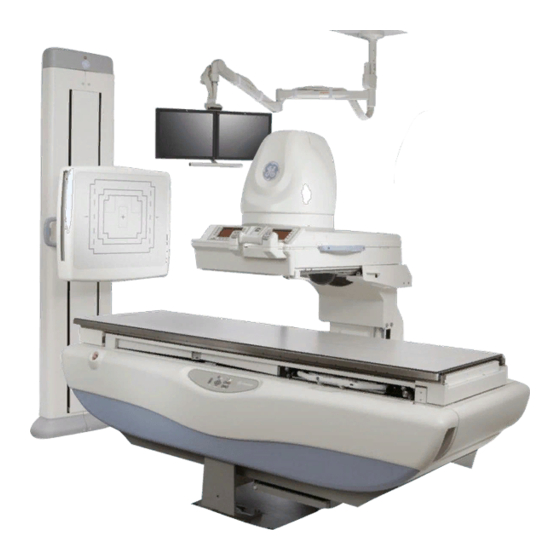
Provides a source to image distance range for a 32 cm II: 72.2 cm (28.4 inches) to 100.2 cm (37.4 inches) or for a 40 cm II: 73.8 cm (29 inches) to 101.8 cm (40.1 inches). ILLUSTRATION 7-1 PRECISION 500D TABLE OVERVIEW IMAGE INTENSIFIER (40 cm) IMAGING DEVICE OPERATOR CONTROL... -
Page 168: Identification And Compliance Plates
ILLUSTRATION 7-2 PRECISION 500D SYSTEM IDENTIFICATION AND COMPLIANCE PLATES TYPICAL IDENTIFICATION PLATE TYPICAL CSA CERTIFICATION PLATE om 5184516-100 Rev. 5... - Page 169 1-2Identification and Compliance Plates ILLUSTRATION 7-2 TABLE 7-1. TABLE 7-1 PRECISION 500D SYSTEM IDENTIFICATION AND COMPLIANCE PLATES Item Component Model Number Plate Type Suspension X–Ray MX 100 X–Ray Tube Casing 46-155400G46 Identification Maxiray 100–18 H.S.; Focal Spots 0.6–1.25°, 12.5° 46–155400G2...
- Page 170 TABLE 7-1 PRECISION 500D SYSTEM IDENTIFICATION AND COMPLIANCE PLATES (continued) SG–80 Vertical Bucky Stand 2402564 Identification SG–120 Vertical Bucky Stand 2402562 Identification Precision 500D Wallstand Reciprocating Bucky 2408636 Identification, CSA, CE (On bucky inside wallstand) Precision 500D Table Cassette Size Sensing Tray...
-
Page 171: Travel Specifications
1-4Travel Specifications ILLUSTRATION 7-3 TRAVEL SPECIFICATIONS FOR INTELLIGENT DIGITAL DEVICE AND PRECISION 500D TABLE TOP om 5184516-100 Rev. 5... -
Page 172: Digital Operator Control Panel
1-5Digital Operator Control Panel Control of digital operation is from the IDD film control panel. ILLUSTRATION 7-4 IDD OPERATOR CONTROL PANEL om 5184516-100 Rev. 5... -
Page 173: Types Of Radiological Examinations In Significant Zone Of Occupancy
1-6Types of Radiological Examinations in Significant Zone of Occupancy The following are the types of radiological examinations for which the Significant Zone of Occupancy is designated to be used: NOTE: Refer to ILLUSTRATION 7-5 through ILLUSTRATION 7-10 for a definition of the area of the Zone of Occupancy and radiation curves. - Page 174 ILLUSTRATION 7-5 DESIGNATION OF SIGNIFICANT ZONE OF OCCUPANCY –TABLE HORIZONTAL om 5184516-100 Rev. 5...
- Page 175 ILLUSTRATION 7-6 DESIGNATION OF SIGNIFICANT ZONE OF OCCUPANCY –TABLE HORIZONTAL (TOP DOWN VIEW) om 5184516-100 Rev. 5...
- Page 176 ILLUSTRATION 7-7 DESIGNATION OF SIGNIFICANT ZONE OF OCCUPANCY –TABLE VERTICAL om 5184516-100 Rev. 5 7-10...
- Page 177 ILLUSTRATION 7-8 DESIGNATION OF SIGNIFICANT ZONE OF OCCUPANCY –TABLE VERTICAL (TOP DOWN VIEW) om 5184516-100 Rev. 5 7-11...
- Page 178 ILLUSTRATION 7-9 RADIATION CURVE TABLE HORIZONTAL NOTE: Air Kerma in one hour normalized for a work load of 3600 mAs @ 120 kVp 3 mA. om 5184516-100 Rev. 5 7-12...
- Page 179 ILLUSTRATION 7-10 RADIATION CURVE TABLE VERTICAL NOTE: Air Kerma in one hour normalized for a work load of 3600 mAs @ 120 kVp 3 mA. om 5184516-100 Rev. 5 7-13...
-
Page 180: Operator Controls And Displays
SECTION 2 OPERATOR CONTROLS AND DISPLAYS 2-1Operator Control Locations ILLUSTRATION 7-11. All Table and Imaging Device operator controls, displays, and indicators are located in two basic operator control areas: • Table Side Control Panel • Imaging Device Operator Control Panel ILLUSTRATION 7-11 INTELLIGENT DIGITAL DEVICE A TABLE OPERATOR CONTROL PANEL LOCATIONS... - Page 181 ILLUSTRATION 7-12 IDD OPERATOR CONTROLS – MAIN GROUPS om 5184516-100 Rev. 5 7-15...
-
Page 182: Imaging Device Operator Controls And Displays - Overview
2-2Imaging Device Operator Controls and Displays – Overview ILLUSTRATION 7-12 TABLE 7-2. TABLE 7-2 IMAGING DEVICE OPERATOR CONTROLS – MAIN GROUPS Item Name Description Notes Auxiliary Digital Operator Provides: Console • Advisory ,essage display. • Digital Controls. • Contrast modifier operator controls. Fluoro Presentation Provides: Operator Console... -
Page 183: Main Operator Console Screen -Basic Controls And Displays
ILLUSTRATION 7-13 MAIN OPERATOR CONSOLE SCREEN – BASIC CONTROLS AND DISPLAYS om 5184516-100 Rev. 5 7-17... - Page 184 2-3Main Operator Console Screen 2-3-1 Main Operator Console Screen –Basic Controls and Displays ILLUSTRATION 7-13 TABLE 7-3. TABLE 7-3 MAIN OPERATOR CONSOLE SCREEN – BASIC CONTROLS AND DISPLAYS Item Operator Activated De-Activated Description Notes Control Display Display Press to lock or unlock the Power Assist does not vertical position of the imag- override the compression...
- Page 185 TABLE 7-3 (CONTINUED) MAIN OPERATOR CONSOLE SCREEN – BASIC CONTROLS AND DISPLAYS Item Operator Con- Activated De-Activated Description Notes trol Display Display Fluoro Timer Display. Flash- Displays only during Fluoro ing display starts after 4.8 acquisition. minutes of fluoroscopy. Press to select FULL or larg- Field size display depends est field of view.
- Page 186 ILLUSTRATION 7-14 MAIN OPERATOR CONSOLE SCREEN – OPTIONAL CONTROLS AND DISPLAYS om 5184516-100 Rev. 5 7-20...
-
Page 187: Main Operator Console Screen -Optional Controls And Displays
2-3-2 Main Operator Console Screen –Optional Controls and Displays ILLUSTRATION 7-14 TABLE 7-4. TABLE 7-4 MAIN SPOT FILM/DIGITAL OPERATOR CONSOLE – OPTIONAL CONTROLS AND DISPLAYS Item Operator Activated De-activated Description Notes Control Display Display Record Displays: Available with Technique 110 kV •... - Page 188 ILLUSTRATION 7-15 AUXILIARY DIGITAL OPERATOR CONSOLE om 5184516-100 Rev. 5 7-22...
-
Page 189: Auxiliary Digital Operator Console
2-3-3 Auxiliary Digital Operator Console ILLUSTRATION 7-15 TABLE 7-5. TABLE 7-5 AUXILIARY DIGITAL OPERATOR CONSOLE Item Operator Activated De-Activated Description Notes Control Display Display Press to increase or decrease Digital FNR selections Digital record Fluoro Noise range from 0 to 6. Reduction (FNR). - Page 190 TABLE 7-5 (CONTINUED) AUXILIARY DIGITAL OPERATOR CONSOLE Item Operator Activated De-Acti- Description Notes Control Display vated Display Press to move the last image hold (LIH) on Available with 2 Monitor monitor 1 to monitor 2 as a reference option. image. This image will remain on monitor 2 until another image is transferred.
-
Page 191: Digital Fluoro Presentation Operator Console
2-4Digital Fluoro Presentation Operator Console TABLE 7-6. TABLE 7-6 DIGITAL FLUORO PRESENTATION OPERATOR CONSOLE CONTROLS AND DISPLAYS Item Operator Activated De-Activated Description Notes Control Display Display Press V to vertically reverse Active when X–Rays are fluoroscopy video presenta- OFF. tion. Press H to horizontally Active when X–Rays are reverse fluoroscopy video... -
Page 192: Digital Multi-Function Operatorcontrol Group
ILLUSTRATION 7-16 DIGITAL MULTI-FUNCTION OPERATOR CONTROL GROUP CONTROLS om 5184516-100 Rev. 5 7-26... - Page 193 2-5Digital Multi-Function OperatorCon- trol Group ILLUSTRATION 7-16 TABLE 7-7. TABLE 7-7 DIGITAL MULTI-FUNCTION OPERATOR CONTROL GROUP CONTROLS Item Operator Motion Description Control Eight-Way Table Top Drive Control. Move control in any of eight directions to drive table top in desired direction: •...
- Page 194 TABLE 7-7 (CONTINUED) DIGITAL MULTI-FUNCTION OPERATOR CONTROL GROUP CONTROLS Item Operator Motion Description Control PREP + EXPOSE bar. Press to initiate PREP + EXPOSE cycle. Two Activate Positions: 1. PREP Position (Bar depressed to 1st click): • Heats Tube filament and brings Tube anode up to exposure speed.
-
Page 195: Precision 500D Table Operator Controls And Displays
ILLUSTRATION 7-17 PRECISION 500D TABLE OPERATOR CONTROLS AND DISPLAYS om 5184516-100 Rev. 5 7-29... - Page 196 2-6Precision 500D Table Operator Controls and Displays ILLUSTRATION 7-17 TABLE 7-8. TABLE 7-8 PRECISION 500D TABLE OPERATOR CONTROLS AND DISPLAYS Item Operator Control Motion Description Emergency STOP Button. Press to turn OFF table power. Turn and release button to restore table power.
- Page 197 ILLUSTRATION 7-17 (CONTINUED) PRECISION 500D TABLE OPERATOR CONTROLS AND DISPLAYS om 5184516-100 Rev. 5 7-31...
-
Page 198: System Specifications
• + indicates vertical motion. • – indicates Trendelenburg motion. Section 3 SYSTEM SPECIFICATIONS 3-1Precision 500D Table Specifications Product specifications for the Precision 500D Table are shown in TABLE 7-9. TABLE 7-9 PRECISION 500D TABLE SPECIFICATIONS Table Travel Longitudinal Travel 60”... -
Page 199: Precision 500D Table Electrical Requirements
Relative Humidity 20% to 80% (non–condensing) 3-1-1 Precision 500D Table Electrical Requirements Electrical Data: Precision 500D Table with Intelligent Digital Device Ratings: 240VAC, 20 amps, Single phase, 50/60 Hz Power Supply Requirements: Generator power unit provides 240VAC, single phase, 50/60 Hz*, 20 amp branch circuit plus ground om 5184516-100 Rev. -
Page 200: Precision 500D Tables, Tubes And Collimators
The following X-Ray Tubes may be used with Intelligent Digital Device and Preci- sion 500D Table (Compatible with fluoro collimator). Refer to Appendix A, Maxiray 100 Tube Units, for further information about these X–Ray Tubes. TABLE 7-10 X–RAY TUBE COMPATIBILITIES FOR IDD/PRECISION 500D TABLE X–RAY TUBE TARGET ANGLE FOCAL SPOT... -
Page 201: Operation
Do not hold onto the power–assist handle during power–up. If power–up tests fail, repeat the power–up test sequence by pressing the red RESET button located on the RCIM. If a failure occurs again, call GE service. 1. Verify the emergency STOP button on the table is disengaged. - Page 202 ILLUSTRATION 7-18 IMAGING DEVICE CARRIAGE om 5184516-100 Rev. 5 7-36...
-
Page 203: Footswitch
4-2Fluoro Exposures After selecting protocol: 1. Set collimator blades manually to desired opening. 2. Press any of the four fluoro buttons, or the footswitch to initiate exposure. 4-2-1 Footswitch The footswitch pedal is a single position footswitch. See ILLUSTRATION 7-19. ILLUSTRATION 7-19 FOOTSWITCH BUTTONS om 5184516-100 Rev. -
Page 204: Taking Digital Exposures
4-3Taking Digital Exposures 4-3-1 Using the Prep/Record Bar 1. Press the PREP/RECORD bar to the first position. 2. Press the PREP/RECORD bar to the second position to expose. 3. Release the PREP/RECORD bar to terminate the exposure. Press the PREP/ RECORD bar to the second position again to expose. -
Page 205: Equipment Positioning For Table Bucky Procedures
ILLUSTRATION 7-20 EQUIPMENT POSITIONING FOR TABLE BUCKY PROCEDURES om 5184516-100 Rev. 5 7-39... - Page 206 4-4Equipment Positioning for Table Bucky Procedures AVOID EQUIPMENT DAMAGE! Damage to the Imaging Device Carriage will occur if the RAD Suspension is moved directly in front of the Imaging Device. Avoid a collision between the RAD Suspension collimator and the Imaging Device Carriage by making sure that the Imaging Device is parked fully at the head-end or foot-end of the table before moving the RAD Suspension into position.
- Page 207 4-4-2 Table Vertical or Trendelenburg AVOID EQUIPMENT DAMAGE! Damage to the 40 cm (16 inch) Image Intensifier will occur if the RAD Suspension is moved closer than a 48 inch (120 cm) SID when the table is angulated vertical or Trendelenburg. Avoid a collision between the RAD Suspension columns and the 40 cm (16 inch) Image Intensifier by maintaining a minimum SID of 48 inches (120 cm) for all table bucky procedures when the table is angulated.
-
Page 208: Ots Radiographic Suspension
CHAPTER 8 OTS RADIOGRAPHIC SUSPENSION SECTION 1 INTRODUCTION 1-1OTS (Overhead Tube Suspension) The Overhead Tube Suspension (OTS) is the positioning device that supports the X–ray tube and OTS Console. Each suspension provides convenient movement and accurate positioning of the equipment. The X–ray Tube Overhead Suspension consists of four major elements –The Overhead Stationary Rail System, –The Telescopic Column and Carriage,... - Page 209 ILLUSTRATION 8-1 OTS COMPONENTS 1-2System Labeling TABLE 8-1 SYSTEM IDENTIFICATION AND COMPLIANCE LABELS OTS radiographic DESIGNATION Automatic Collimator suspension MODEL NUMBER 2399849, B2055TR AF01A om 5184516-100 Rev. 5...
-
Page 210: Overhead Rail System
ILLUSTRATION 8-2 LOCATION OF SYSTEM IDENTIFICATION AND COMPLIANCE LABELS LABEL LABEL BEHIND COVER 1-3 Overhead Rail System The overhead rail system consists of the stationary rails (ceiling mounted) and a bridge that travels longitudinally (LONG) along the rails. Guide bearings maintain alignment of the bridge with the rails and the X–ray table. -
Page 211: Telescopic Column And Carriage
The vertical load is balanced by a spring counterpoise system within the carriage. The counterpoise system is equipped with a safety locking feature to prevent the tube unit from falling in the event of spring or main cable failure. Adding an acces- sory such as a collimator extension cylinder may cause the suspension to be slightly out of balance. -
Page 212: Tube Support Rotation
1-6Tube Support Rotation The tube unit can be pivoted about the vertical axis of the telescopic column (tube support rotation) 180° in each direction from the table “NORMAL” position. It auto- matically locks in each 30° position. To release it, depress the tube support rota- tion lock lever on the right side of the tube support. -
Page 213: X-Ray Tube Angulation
1-7X–ray Tube Angulation The other rotational feature of the tube support permits TUBE ANGULATION about the short axis (front to back). The amount of angulation is indicated on the user interface. Limits of angulation are 180° in either direction from the X–ray beam down position. -
Page 214: Over Head Ceiling Suspension User Interface
1-8Over Head Ceiling Suspension User Interface The in–room user interface allows the operator to make receptor type, kV and mAs selections without returning to the System Console. Positioning of the X–ray tube can be performed with one or two–hands. The locks and lock releases on the user interface make positioning the X–ray tube easy. - Page 215 TABLE 8-2 OTS OPERATOR CONTROLS AND INDICATORS Item Title Type Description kV Display Indicator Display exposure kV. mAs Display Indicator Display exposure mAs. kV Increment and Decrement Control Increase or Decrease exposure kV. Keys mAs Increment and Decrement Control Increase or Decrease exposure mAs. Keys Unit Display Indicator...
-
Page 216: Key Switch On Ots Console
1-8-1 Key Switch on OTS Console The Key Switch is located on the back of the OTS User Interface. The Key Switch is intended for use when a system failure has occurred. The OVERRIDE position disables the exposure hold interlocks and allows expo- sure. - Page 217 ILLUSTRATION 8-8 AUTOMATIC COLLIMATOR CONTROLS Locking lever for 90° rotation of the collimator about vertical axis The collimator stops only in 0° position. Adjusting knob for format height collimation (Turning to the left closes the collimator, turning to the right opens the collimator) Adjusting knob for format width collimation (Turning to the left closes the collimator, turning to the right opens the collimator) X–ray field illumination and linear light localizer on/off...
-
Page 218: Locking Lever
2-1 Locking lever The locking lever locks the compensating filters, templates, etc. inserted in the accessory rails of the multileaf collimator in place to prevent them from falling out To remove an accessory from the collimator, the locking lever must be pressed in until the compensating filter, templates etc., can be removed. -
Page 219: Bottom View Of The Collimator
2-3Bottom View of the Collimator ILLUSTRATION 8-10 AUTOMATIC COLLIMATOR BOTTOM VIEW On/Off switch (4) for illumination of full–field and linear light localizer. Linear LASER light localizer. Centering cross for positioning. Locking lever for accessories. 2-4Linear LASER Light Localizer The linear LASER light localizer provides the axis mark for longitudinal centering which is lined up with the centering mark on the handle of the cassette loading device. -
Page 220: Rear View Of Collimator
2-6Rear View of Collimator (1) Locking lever for 90° rotation of collimator around vertical axis ILLUSTRATION 8-11 AUTOMATIC COLLIMATOR REAR VIEW Locking lever for rotation of collimator around vertical axis. Identification labels. 2-7Collimator Lamp Changing 2-7-1 Changing Lamps on the Collimator (Model 2266999) The bulb of the collimator may be changed if necessary. - Page 221 ILLUSTRATION 8-12 AUTOMATIC COLLIMATOR LAMP LOCATION TWO ALLEN HEAD SCREWS LAMP HOUSING Switch off the system. Remove two Allen head screws on lamp housing. Remove lamp housing. Remove the two Allen contact screws on the lamp. Replace the halogen bulb. Do not touch new lamp with your bare fingers.
-
Page 222: Changing Lamps On The Collimator (Model 5234954)
2-7-2 Changing Lamps on the Collimator (Model 5234954) )The Automatic Collimator uses a special collimator light bulb and it MUST be replaced with part number 2271727. Other lamps may not meet HHS require- ments. The X-ray field to light field is aligned in the factory. This collimator bulb requires no alignment for X-ray to light field, since the filament is in the same place in all bulbs. - Page 223 ILLUSTRATION 8-13 LAMP COVER Fastening Screws om 5184516-100 Rev. 5 8-16...
- Page 224 ILLUSTRATION 8-14 LIGHT LOCALIZER HEAT SHEILD Fastening Screws Heat Shield om 5184516-100 Rev. 5 8-17...
- Page 225 ILLUSTRATION 8-15 HALOGEN LAMP Insert the halogen bulb until both contacts are touching the socket stop position. om 5184516-100 Rev. 5 8-18...
-
Page 226: Rotating The Collimator 90° Around The Vertical Axis
2-8Rotating the Collimator 90° Around the Vertical Axis Move locking lever on multileaf collimator toward front panel, i.e. toward the oper- ator. ILLUSTRATION 8-16 AUTOMATIC COLLIMATOR ROTATION LOCKING LEVER LOCKING LEVER Multileaf collimator in 0° lock–in position – The 0° lock–in position of the multileaf collimator is released by actu- ating the locking lever. -
Page 227: Specifications
SECTION 3 SPECIFICATIONS NOTE: Because X–ray equipment produces radiation, special precautions may need to be taken or special site modifications may be required. The General Elec- tric Company does not make recommendations regarding radiation protec- tion. It is the purchaser’s responsibility to consult a radiation physicist for advise on radiation protection in X–ray rooms. - Page 228 TABLE 8-5 OTS SPECIFICATIONS Parameter Specification Longitudinal Focal Spot Travel 2757 mm (108–1/2 in.) Lateral Focal Spot Travel 1200 mm (47–1/4 in.) Vertical Focal Spot Travel 1500 mm (59 in.) Horizontal Tube Rotation +/– 180 degrees; detents at each 90 degree position Vertical Tube Rotation + 110/–20 degrees Focal Spot to Ceiling Distance (Horizontal)
- Page 229 TABLE 8-6 AUTOMATIC COLLIMATOR SPECIFICATIONS Parameter Specification Collimator Digital version with automatic formats collimation system and light localizer for rectangular collimation with linear light localizer and rails for secondary filters Operation Mode Automatic Manual Dimensions 349 L x 237W x 181 H (mm) Weight 9.8 +/–...
-
Page 230: Sg120 Vertical Bucky Stand
CHAPTER 9 SG–80 & SG120 VERTICAL BUCKY STAND SECTION 1 INTRODUCTION The SG80/120 is defined as a Vertical Bucky Stand suitable for providing common radiographic examinations, including chest films and oblique angle radiography. With the right choice of X-ray tube supports, tubes and generators, the SG80/120 is able to provide vertical and horizontal off-table radiography. -
Page 231: Parts Of The Equipment
SECTION 2 PARTS OF THE EQUIPMENT The main parts of the SG80/120 are detailed in ILLUSTRATION 9-2. ILLUSTRATION 9-2 2-1 Column Assembly The column assembly includes the next main parts: • Bucky support assembly: joins the column assembly to the bucky assembly means of the vertical carriage that moves along the guide on the column. -
Page 232: Bucky Assembly
2-2 Bucky Assembly Includes the bucky, that is mounted to the bucky support behind the front panel. Includes a cassette tray, suitable for all standard cassette sizes. In the bucky assembly are also located other parts, such as the grid (optional) and the ion chamber, used for AEC exposures. -
Page 233: Cassette Loading
3.Set the bucky assembly at the desired height, depending on the study to be per- formed. 4.Release the key on the vertical lock handle and check the bucky assembly remains locked in the desired position. NOTE: The vertical lock handle is located on the LEFT side behind the bucky assembly, but this configuration can be easily field configured if needed. - Page 234 ILLUSTRATION 9-3 Cassette Loading Procedure (See ILLUSTRATION 9-3) 1. Extract the cassette tray pulling by its handle. 2.Open cassette-clamp locking assembly. Spread out and separate the clamps. 3.Insert the cassette support bracket into the appropriate holes. 4.Insert the cassette between the cassette clamps, resting it on the cassette sup- port bracket, Reposition the clamps against the cassette and close the cas- sette-clamp locking assembly.
-
Page 235: Cassette Removal
TO AVOID THE CASSETTE-CLAMP LOCKING ASSEMBLY CAN BE DAMAGED, ALWAYS CLOSE IT BEFORE INSERTING THE CASSETTE TRAY INTO THE BUCKY TRAY SLOT USE CAUTION TO AVOID CASSETTE SENSING ARM DEFORMATION. SHAPE IMPORTANT OBTAIN ACCURATE FIELD PLACEMENT. IF THE ARM IS DAMAGED, IT HAS TO BE REPLACED. DO NOT TRY TO REPAIR THE ARM IN CASE IT BECOMES DEFORMED. -
Page 236: Frontal Panel
4-6 Frontal Panel The bucky assembly mechanism and grid can be easily accessed by removing the front panel of the SG80/120. Loosen the screws that hold the front panel to the bucky support and remove it with care (Fig 4.5). ILLUSTRATION 9-4 Front Panel Removal 4-7 SG120-Specific Funtionalities... -
Page 237: Bucky Angulation
ILLUSTRATION 9-5 Bucky Rotation Procedure: See ILLUSTRATION 9-5 1. Release the lock lever . 2. Rotate the bucky to position 3. Put the lock lever back into locked position. NOTE: The bucky can be rotated CW (clockwise) or CCW (counter-clockwise). To avoid degradation of image quality and loss of bucky functionality, it is recommended not to perform exposures with the bucky in other position than 0 degrees or 180 degrees. -
Page 238: Periodic Maintenance
ILLUSTRATION 9-6 Bucky Angulation Procedure: See ILLUSTRATION 9-6 1. Press one of pushbuttons located behind the bucky support 2.Keeping the push-button pressed, angulate the bucky to the desired position. 3.Release the push-button in order the bucky to remain locked. SECTION 5 PERIODIC MAINTENANCE 5-1 Maintenance Information In order to assure continued safe performance of x-ray equipment, a periodic... -
Page 239: Labeling
MAINTENANCE FREQUENCY PROCEDURE ITEM (MONTHS) GENERAL Visual Inspection Check for debris that would indicate abnormal wear General cleaning As required Wipe exterior parts using soft cloth, and painting water and mils soap. Vacuum interior if any dust or lints is present Functional checks Perform tasks described in SG80/ 120 Service Manual... -
Page 240: Specifications
SECTION 7 SPECIFICATIONS 7-1 Electrical Requirements Electrical requirements for the SG80/120 vertical bucky stand: FREQUENCY (Hz) VOLTAGE (V) MAX CURRENT (A) PRODUCT Continu- Moment. SG80/120 7-2 Product Dimensions DIMENSIONS RODUCT DEPTH WIDTH WEIGHT HEIGHT 373 mm 373 mm 652 mm 652 mm 2235 mm 180 Kg... -
Page 241: Sg120 Specifications
7-4 SG120 Specifications 7-4-1 Wall Stand “General” Parameter Specification Weight 220kg (485.1 lbs) Height 2235 mm (87.99 in) Min. Width 652 mm (25.67 in) Max. Width 915 mm (36.02 in) Min. Depth 687 mm (27.05 in) Max. Depth 927 mm (36.5 in) Front panel height 64.2 cm (25.2 in) Front panel width... -
Page 242: Vertical Bucky Stand
CHAPTER 10 SG–100 VERTICAL BUCKY STAND SECTION 1 INTRODUCTION The SG-100/SG-120 system is defined as a Tilting/Rotating Vertical Bucky Stand suitable for providing common radiographic examinations, including chest films and oblique angle radiography. Combined with suitable X-ray tube supports, tubes and generators, the SG-100/SG-120 is able to provide vertical and horizon- tal off-table radiography. - Page 243 ILLUSTRATION 10-2 Example, SG–100 componts shown om 5184516-100 Rev. 5 10-2...
-
Page 244: Safe Operation Precautions
SECTION 2 SAFE OPERATION PRECAUTIONS To ensure efficient and safe operation of equipment keep the Operating Manual with the equipment at all times and periodically review the Operation and the Safe Operation Precautions sections. FOR CONTINUED SAFE USE OF THIS EQUIPMENT, FOLLOW THE INSTRUCTIONS CONTAINED IN THIS OPERATING MANUAL. - Page 245 Vertical Bucky travel: • Top edge of Bucky in vertical position: from 24.57” (624 mm) to 72.60” (1844 mm). • Top edge of Bucky in horizontal position: from 20.77” (527.5 mm) to 68.07” (1729 mm). Tolerance: + 0.0” (0 mm), –0.6” (15 mm) The mechanical backup lock engages within 1/2”...
-
Page 246: Vertical Positioning
ILLUSTRATION 10-3 VERTICAL POSITIONING 3-4Bucky Rotation The Bucky can be rotated from 0° to 180°. A rotation lock, located behind the Bucky, holds the Bucky in position. Refer to ILLUSTRATION 10-4. To change position release the lock lever, rotate the Bucky to the desired position and put the lock lever back into locked position. -
Page 247: Bucky Rotation
Exposures should not be made with the Bucky in any other position as this may result in a degradation of image quality and loss of Bucky functionality. WHILE EXPOSURES WITHIN 30° OF THE 0° AND 180° POSITIONS ARE NOT RECOMMENDED, THE BUCKY WILL FUNCTION IN THIS RANGE. A DEGRADATION IN IMAGE QUALITY MAY RESULT, HOWEVER. -
Page 248: Bucky Angulation
ILLUSTRATION 10-5 BUCKY ANGULATION 3-6Hinged Front Panel A hinged front panel enables easy access to the Bucky grid and mechanism. Refer to ILLUSTRATION 10-6. To open the panel, turn the thumb screws on the bottom of the panel then lift the panel up. -
Page 249: Manual Cassette Tray
ILLUSTRATION 10-6 LIFTING FRONT HINGED PANEL HAZARDOUS VOLTAGE CAN CAUSE SEVERE INJURY OR DEATH. WHEN CHANGING/REPLACING GRID, TURN OFF POWER. 3-7Cassette Loading The SG–100 is equipped with a manual cassette tray which is inserted into the Bucky tray slot. 3-8Manual Cassette Tray The manual cassette tray accepts cassette sizes ranging from 5”... -
Page 250: Aec Detector Areas
3. Insert the cassette support bracket into the appropriate holes. 4. Insert the cassette between the cassette clamps, resting it on the cassette support bracket, then reposition the clamps against the cassette and close the cassette-clamp locking assembly. 5. Push the cassette tray back into the Bucky. NOTE: To prevent damage to the cassette-clamp locking assembly always close it prior to inserting (pushing) the cassette tray into the Bucky. -
Page 251: Alignment For Automatic Collimation
cal alignment is not critical, and tilted tube techniques may be used without undue cutoff. 3-13Manual Cassette Tray The center of the cassette tray handle is marked to indicate the vertical center of the bucky. Move the Bucky or the tube in order to align the collimator light with this center mark. -
Page 252: Specifications
ILLUSTRATION 10-7 FRONT PANEL AEC DETECTOR AREAS * UNLESS CASSETTE IS ECCENTRICALLY POSITIONED SECTION 4 SPECIFICATIONS 4-1General Dimensions & Weight DIMENSIONS Height ................84.88 in 2156 mm Width ................26.93 in 684 mm Depth ................25.82 in 656 mm (Refer to Illustration “General Dimensions”). om 5184516-100 Rev. - Page 253 WEIGHT Weight 409 lb ............... 186 kg 4-2Column Assembly Height ................84.88 in 2156 mm Width ................13.86 in 352 mm Depth ................4.98 in 126.5mm (Refer to Illustration “General Dimensions”). 4-3Front Panel Front Panel Height ............23.23 in 590 mm Front Panel Width ............
- Page 254 ILLUSTRATION 10-8 GENERAL DIMENSIONS 4-6Accessories & Options The following accessories and options are available for use with the SG–100 Ver- tical Bucky Stand. For information concerning the items consult your local GE rep- resentative. • Head and Hip Clamps. •...
- Page 255 THIS PAGE INTENTIONALLY LEFT BLANK om 5184516-100 Rev. 5 10-14...
-
Page 256: Jedi Generator
CHAPTER 11 JEDI GENERATOR SECTION 1 INTRODUCTION TABLE 11-1 ALTITUDE AND ATMOSPHERIC PRESSURE ALTITUDE ATMOSPHERIC PRESSURE PRODUCT OR IN–USE STORAGE IN–USE STORAGE COMPONENT MIN. MAX. MIN. MAX. MIN. MAX. MIN. MAX. Generator –30.5 2440 m –30.5 m 3048 m 10 psi 15.4 psi 7 psi 15.4 psi... - Page 257 ILLUSTRATION 11-1 JEDI GENERATOR CABINET om 5184516-100 Rev. 5 11-2...
-
Page 258: Generator Cabinet Specifications
TABLE 11-3 GENERAL CABINET SPECIFICATIONS Dimensions Generator Cabinet Height: 1600 mm Width: 550 mm Depth: 450 mm Weight: 150kg NOTE: All specifications do not include measurement instumentation accuracy. 3-2General Input Power Specifications TABLE 11-4 MODEL DEPENDENT SPECIFICATIONS PARAMETER JEDI GENERATOR Input Voltage 380/400/415/440/460/480VAC three phase and Ground without neutral Daily Voltage Variations... - Page 259 11-4 Generator Ouput Power: TABLE 11-5 JEDI GENERATOR POWER 65kW 80kW 40–80 800 mA 1000 mA 630 mA 800 mA 500 mA 630 mA 400 mA 500 mA The JEDI can deliver the power specified in this output for at least 100ms, depending on the X–ray tube used.
- Page 260 TABLE 11-8 ACCURACY READINGS ON CONSOLE READOUTS Mode : 3 point Selectable Resultant mA 26% ms 26A% mAs 26% increments Non–AEC 0.5 thru 630 mA 32 steps JEDI 65 kW: 10 thru 1 thru 630ms 39 steps 0.5 thru 630 mA 800 mA/20 steps 32 steps JEDI 80 kW: 10 thru...
- Page 261 TABLE 11-9 ACCURACY OF CONSOLE READOUTS NOTE: In RAD mode, kVp accuracy is ensured after 10ms. Display before exposure Conditions parameter mode Basic Accuracy Radiography +/– (3%, +2 kVp) Exposure +/– (10%, +1 mA) Time <= 40 3 point timer +/–(5%, +0.5ms) AEC (2/3 point) +/–...
- Page 262 4-1Power Line Requirements TABLE 11-10 MINIMUM WIRE SIZE (65 KW) PARAMETER THREE PHASE GENERATOR – 65 KW Input Voltage 380VAC 400 VAC 415 VAC 440 VAC 460 VAC 480 VAC Wire Size Length 15 m (50 ft.) 16 mm2 16 mm2 16 mm2 16 mm2 16 mm2...
-
Page 263: X-Ray Interlock Systems
TABLE 11-13 KVA LOAD CHARACTERISTICS 80KW Phase Nominal line Voltage (Vac) Voltage Range (Vac) +/–10% +/–10% +/–10% +/–10% +/–10% +/–10% Momentary Line Current (Amp) Continuous Line Current (Amp) 6 5. Power demands (kVA) Frequency 47 / 53Hz and 57/63Hz 4-2X–Ray Interlock Systems ”Deadman’s switch”... -
Page 264: Patient Step
CHAPTER 12 ACCESSORIES SECTION 1 TABLE ACESSORIES 1-1Patient Step The patient step (ILLUSTRATION 12-1) provides patient convenience getting on and off the table. The step is attached to the underside of the table body to the right of the front support. Table angulation is prevented when the step is pulled out. -
Page 265: Foot Rest
1-2Foot Rest TO PREVENT IMPROPER ATTACHMENT AND POTENTIAL INJURY TO PATIENT, USE THIS FOOTREST ONLY ON THE TABLE FOR WHICH IT HAS BEEN ADJUSTED. Installing the foot rest at the set of slots closest to the end of the tabletop provides easier patient boarding. The foot rest is engaged on the table top in the same manner as shown for the shoulder rest on ILLUSTRATION... -
Page 266: Optional Table Accessories
SECTION 2 OPTIONAL TABLE ACCESSORIES 2-1Shoulder Rest The shoulder rest (Illustration 10–3) is engaged on the table top in the same manner as the foot rest. The plunger locks permit adjustment of the pad position in 1/2” increments. ILLUSTRATION 12-3 SHOULDER REST 2-2Compression Device The compression device is not intended to be used for patient support or restraint. - Page 267 2-3Myelographic Operation For myelographic procedures, the Horizontal Stop selection located on the table control panel should be off. This inhibits accidental motion of the cone during the procedure. SET THE MANUAL MYELOGRAPHIC STOP ON THE FLUORO CARRIAGE (ILLUSTRATION 12-5) BEFORE BEGINNING PROCEDURE.
-
Page 268: Arm Board (Optional)
2-5Arm Board (Optional) The arm board (ILLUSTRATION 12-6) supports the patient’s arm during catheter- ization or other intravenous procedures and attaches over all but the middle of the table top. To install the arm board on the table top: 1. Check that the lock lever (on underside) is turned so that its eccentric hub is withdrawn into the recess opposite the key on the clamping surface. -
Page 269: Knee Crutches (Optional)
2-6Knee Crutches (Optional) Used for urological or gynecological examinations the crutch supports for the knees are adjustable (ILLUSTRATION 12-7). To attach: 1. Spread the hinges on each side, 2. Place on the table top so that the catches on the hinges are roughly in line with a set of notches and release the hinges. -
Page 270: Vertical Cassette Holder (Optional)
2-7Vertical Cassette Holder (Optional) The vertical cassette holder is used for cross–table radiography. It can be attached to the table top along the entire length. To install the holder; 1. Engage it on the edge of the table top. 2. Slide it to the desired position. 3. - Page 271 THIS PAGE INTENTIONALLY LEFT BLANK om 5184516-100 Rev. 5 12-8...
-
Page 272: Maxiray™ 100 Tube Units
APPENDIX A MAXIRAY™ 100 TUBE UNITS ILLUSTRATION A-1 MAXIRAY 100 TUBE UNITS SECTION 1 APPLICATION High–speed, 4–inch (100 mm) diameter rotating–anode tube unit and inserts for high–energy radiographic procedures. SECTION 2 FEATURES • Polyrhenium target, manufactured by General Electric minimizes surface distortion and provides increased radiation output. -
Page 273: Tube Housing
TABLE A-1 MAXIRAY 100 TUBE UNITS New Tube Unit Exchange Tube Unit Focal Spot Color D1179E(FL) D0579E(FL) 0.6–1.0 Oyster gray D1279E(FL) D0679E(FL) 0.6–1.0 Mist gray *D1172E(09) *D0572E(09) 0.6–1.0 Oyster gray *D1272E(09) *D0672E(09) 0.6–1.0 Mist gray *D1173E(18) *D0573E(18) 0.6–1.0 Oyster gray *D1273E(18) *D0673E(18) 0.6–1.0... -
Page 274: Tube Insert
Rating plates on housing list focal spot sizes and serial numbers. Leakage technique factors: Radiographic tube unit–150 kVp, 4 mA Fluoroscopic tube unit–150 kVp, 5 mA Minimum inherent filtration: Tube housing – 0.3 mm aluminum at 150 kVp Tube insert – 0.8 mm aluminum at 150 kVp Tube Insert Glass envelope facilitates “near”... -
Page 275: Radiographic Ratings
Individual fluoroscopic and radiographic exposure limits govern allowable tech- niques until the heat storage capacity of the anode is reached. Thereafter, contin- ued operation can be maintained only at the limit of the anode dissipation rate of 75,000 heat units per minute until the tube unit capacity of 1,500,000 heat units is reached. -
Page 276: Warranty
Human Services pursuant to the Radiation Control of Health and Safety Act. This X–Ray Tube Unit Assembly is intended to be installed in a GE X–ray appara- tus that may or may not be CE Marked. Installing a CE Marked X–Ray Tube Assembly in a non–CE Marked system does not make the whole system CE... - Page 277 ILLUSTRATION A-2 OUTLINE DRAWING OUTLINE DRAWING MX–100–09 AND 100-18 NOTE: ALL DIMENSIONS SHOWN ARE IN INCHES (MM) NOMINAL VALUES OUTLINE DRAWING MX–100–FL NOTE: ALL DIMENSIONS SHOWN ARE IN INCHES (MM) NOMINAL VALUES om 5184516-100 Rev. 5...
- Page 278 ILLUSTRATION A-3 TUBE HOUSING COOLING CURVE MAXIRAY 100–09 and 18 MAXIRAY 100–FL (MODEL NO. 46–155400) (MODEL NO. 46–155500) MAX. COOLING CURVE= MAX. COOLING RATE = 60,000 HU/MN 75,000 HU/MN TIME IN MINUTES TIME IN MINUTES ILLUSTRATION A-4 ANODE COOLING CURVE MAXIRAY TIME IN MINUTES om 5184516-100 Rev.
-
Page 279: Radiographic Tube Ratings
SECTION 8 RADIOGRAPHIC TUBE RATINGS These charts are based on a target temperature equivalent to 25% of storage (75% remaining). For heavy–duty operation where this temperature is exceeded, 80% of the rating must be used. Warm–Up Procedure The first exposures of the day, or following two or more hours shutdown, must be made at a MEDIUM POWER level rather than at voltages or currents near maxi- mum ratings. -
Page 280: 12.5° (218 Mrad) 3Ø, Low Speed, 50 Hz, 2850 Rpm
12.5° (218 mRad) 3ø, Low Speed, 50 Hz, 2850 rpm ILLUSTRATION A-5 0.6, 1.0 MM om 5184516-100 Rev. 5... -
Page 281: 12.5° (218 Mrad) 3Ø, Low Speed, 60 Hz, 3400 Rpm
12.5° (218 mRad) 3ø, Low Speed, 60 Hz, 3400 rpm ILLUSTRATION A-6 0.6, 1.0 MM om 5184516-100 Rev. 5 A-10... - Page 282 12.5° (218 mRad) 3ø, Low Speed, 50 Hz, 2850 rpm ILLUSTRATION A-7 0.6, 1.25 MM om 5184516-100 Rev. 5 A-11...
- Page 283 12.5° (218 mRad) 3ø, Low Speed, 60 Hz, 3400 rpm ILLUSTRATION A-8 0.6, 1.25 MM om 5184516-100 Rev. 5 A-12...
- Page 284 12.5° (218 mRad) 3ø, Low Speed, 50 Hz, 2850 rpm ILLUSTRATION A-9 0.6, 1.5 MM om 5184516-100 Rev. 5 A-13...
- Page 285 12.5° (218 mRad) 3ø, Low Speed, 60 Hz, 3400 rpm ILLUSTRATION A-10 0.6, 1.5 MM 12.5° om 5184516-100 Rev. 5 A-14...
-
Page 286: 12.5° (218 Mrad) 3Ø, High Speed, 50/60 Hz, 10,000 Rpm
12.5° (218 mRad) 3ø, HIGH SPEED, 50/60 Hz, 10,000 rpm ILLUSTRATION A-11 0.6, 1.0 MM om 5184516-100 Rev. 5 A-15... - Page 287 12.5° (218 mRad) 3ø, HIGH SPEED, 50/60 Hz, 10,000 rpm ILLUSTRATION A-12 0.6, 1.25 MM om 5184516-100 Rev. 5 A-16...
- Page 288 8-10 12.5° (218 mRad) 3ø, HIGH SPEED, 50/60 Hz, 10,000 rpm ILLUSTRATION A-13 0.6, 1.5 MM om 5184516-100 Rev. 5 A-17...
-
Page 289: Mammography Ratings
SECTION 9 MAMMOGRAPHY RATINGS 12.5° (218 mRad) 3ø, 50/60 Hz, 2850/3400 RPM ILLUSTRATION A-14 0.6, 1.25, 1.5 mm om 5184516-100 Rev. 5 A-18... -
Page 290: Rapid Film Sequence Ratings
SECTION 10 RAPID FILM SEQUENCE RATINGS 10-1 0.6, 1.0, 1.25 12.5_ (218 mRad) 1 Phase, 10,000 rpm, 50/60 Hz Rapid sequence rating charts are used because of severe demands on the radio- graphic tube. In contrast to normal radiography, where cooling is occuring between exposures, serial radiography does not allow significant cooling of the focal spot track between exposures. - Page 291 TABLE A-2 DUTY CYCLE CHART Exposure Time FILM FRAME RATE Seconds 2/sec. 4/sec. 6/sec. 8/sec. .005 1.0% 2.0% 3.0% 4.0% .0064 1.28% 2.56% 3.84% 5.12% .008 1.6% 3.2% 4.8% 6.4% .010 2.0% 4.0% 6.0% 8.0% .0125 2.5% 5.0% 7.5% 10.0% .016 3.2% 6.4%...
- Page 292 10-2 12.5° (218 mRad) 3 Phase, 10,000 rpm, 50/60 Hz ILLUSTRATION A-15 0.6 , 1.0 MM om 5184516-100 Rev. 5 A-21...
- Page 293 10-3 3Ø , KILOWATT RATINGS 12.5° (218 mRad) TABLE A-3 FOCAL SPOT SINGLE LOAD RATING 0.6 MM EXPOSURE TIME (S) POWER (KW) 0.01 34.7 22.1 ILLUSTRATION A-16 0.6 MM MAXIMUM EXPOSURE TIME IN SECONDS TABLE A-4 FOCAL SPOT SINGLE LOAD RATING 1.0 MM EXPOSURE TIME (S) POWER (KW) 0.01...
- Page 294 ILLUSTRATION A-17 1.0MM TABLE A-5 FOCAL SPOT SINGLE LOAD RATING 1.25 MM EXPOSURE TIME (S) POWER (KW) 0.01 108.3 28.3 om 5184516-100 Rev. 5 A-23...
- Page 295 ILLUSTRATION A-18 1.25 MM TABLE A-6 ® MAXIRAY 100 TUBE FILAMENT RATINGS 12.5° (218 MRAD) TARGET Filament (mm) Ampères Volts 3.4 – 5.5 2.0 – 9.0 3.4 – 6.5 2.0 – 11.0 1.25 4.3 – 6.5 4.0 – 15.0 om 5184516-100 Rev. 5 A-24...
-
Page 296: Planned Maintenance
If desired, arrangements can usually be made to furnish periodic and/ or emergency service on a contract basis. A GE Medical Systems represen- tative will be glad to discuss this plan. -
Page 297: Image Quality Testing
In case of doubt about condition of this equipment, con- tact a GE Service representative. Once a month, external parts and exposed tracks, on which rollers move, should be wiped to remove any foreign material that may have accumulated. - Page 298 ILLUSTRATION B-1 FLAT FIELD PHANTOM AND QAP PHANTOM FLAT FIELD PHANTOM QAP PHANTOM The flat field phantom is used to check: • Fluoro Noise • Record Noise • Left Right Brightness Non Uniformity om 5184516-100 Rev. 5...
-
Page 299: How To Perform The Quality Assurance Process
A failed status indicates that one or more of the image quality parameter values fall outside the system specification limits. If a system fails QAP, operator is advised to call GE Service to make the proper sys- tem adjustments or calibrations to regain optimal system image quality. Periodic QAP tests are recommended to assure optimal system operation. - Page 300 ILLUSTRATION B-3 QAP SELECTION 6. The Image Quality screen will appear. The QAP application has 3 steps: Step 1: Flat field, low dose (fluoroscopy) image acquisition Step 2: Flat field, normal dose (digital record) image acquisition Step 3: QAP Phantom, normal dose (digital record) image acquisition NOTE: Make sure the default Horizontal and Vertical Settings are restored before starting QAP unit.
- Page 301 After the “QAP” is started, the system will take several seconds to compute system electronic noise. Then, the screen will transition to the Step 1 Instruction Screen with the fol- lowing instructions: Step 1 of 3 • Adjust the tower so the the SID is equal to the value displayed in the screen instructions, +/-5 mm.
- Page 302 7. When the “CONTINUE” button is pressed, the screen will transition to the Step 2 Instruction Screen with the following instructions: Step 2 of 3 • Adjust the tower so the the SID is equal to the value displayed in the screen instructions, +/-5 mm.
- Page 303 8. When the “CONTINUE” button is pressed, the screen will transition to the Step 3 Instruction Screen with the following instructions: Step 3 of 3 • Adjust the tower so the the SID is equal to the value displayed in the screen instructions, +/-5 mm.
- Page 304 “Quality Assurance Program has been completed successfully - Image quality is optimal” Failure message when image quality is not optimal: “Quality Assurance has failed. - Image quality is not optimal. Please call GE Service” If a failure message is displayed, please call GE Service.
-
Page 305: General
Aside from routine maintenance, any abnormal noise, vibration or unusual perfor- mance should be reported immediately to a GE Medical Systems representative. Before calling for service, however, be sure the equipment is being operated in accordance with the foregoing instructions. -
Page 306: Periodic Maintenance Schedule
Periodic Maintenance Schedule MAINTENANCE ITEM FREQUENCY (MONTHS) SAFETY Check all counterweight cables 6 months Check mounting bolts 6 months Check ground leakage 6 months Check loose or damaged hardware and accessories months FUNCTIONAL Inspect components 6 months Vacuum dust filters in cabinets, console, system control, & digital 6 months Clean and lubricate 6 months... -
Page 307: Hhs Testing (Us Only
On the console, clean the frame and the mylar surface with a lint–free cloth moist- ened with alcohol. DO NOT: 1. Use alkaline products. 2. Place objects on the mylar surface which are likely to cause scratches. 3. Use the console to write on. IN THE EVENT OF EQUIPMENT CONTACTING BROKEN SKIN OR BEING USED... -
Page 308: Glossary/Terms
Digital Record: Diagnostic information obtained with a image intensifier/video digitizing system and recorded on computer disk. Table Bucky: Radiographic recording with an overhead X–Ray tube (Tube–2) and film receptor within the Precision 500D table. ILLUSTRATION C-1 LONGITUDINAL/LATERAL LATERAL LONGITUDINAL om 5184516-100 Rev. 5... -
Page 309: System Terms
Head End: Looking at the front side of the table, the head of the patient is at the left end of the table. With reference to film, it is the side of the film closest to the head end of the table. -
Page 310: Digital Imaging System Terms
SECTION 2 DIGITAL IMAGING SYSTEM TERMS Symbols The following symbols are used on the system hardware. This symbol indicates the system is rated as Type B Equipment according to IEC 601 regulations. This symbol is located on the rear panel of the electronics cabi- net. - Page 311 This symbol indicates the position of the lock for the front access panel of the PC cabinet. The symbol is located just above the lock, on the left edge of the front panel. This symbol indicates the PC Reset switch for the system. This symbol and switch are located on the front panel of the electronics cabinet, below the main ON/OFF switch.
- Page 312 This symbol indicates the Volume control for the CD Player headset. This switch does not function for the system. This symbol is located on the front panel of the electronics cabinet, on the Compact Disk player unit. Direct Current and alternating current. Earth (ground) –...
- Page 313 Off (power; disconnection from the mains) On (power; connect to the mains) “Off” (only for a part of Equipment) “On” (only for a part of Equipment) Type B Equipment. Dangerous voltage Non–ionizing radiation. om 5184516-100 Rev. 5...
-
Page 314: Abbrevations
When this LED symbol is lit it indicates the Hard Disk Drive unit is active. This symbol is located on the front panel of the electronics cabinet. When this LED symbol is lit, it indicates the power to the system is ON. This sym- bol is located on the front panel of the electronics cabinet. - Page 315 Abbreviation Definition Millimeters Magneto Optical Drive Modulation Transfer Function Milli–Rad PACE Post–Acquisition Copy & Enhance Personal Computer Part Number Random Access Memory Radiation/Fluoroscopy S/N: Serial # Reverse Root–Mean–Squared Region of Interest Underwriters Laboratories Micro–Rad V Volts Video Casette Recorder Window (Contrast) om 5184516-100 Rev.
-
Page 316: Modes Of Operation
APPENDIX D MODES OF OPERATION The P500D has 4 operating modes: • Fluoroscopy • Pulsed Fluoroscopy • Digital Subtraction Angiography (DSA) • Radiography The availability of a given mode depends on the selected protocol that is to be performed. That is, not all protocols have all modes available. Protocols that require the acquisition of both Fluoro and Radiography images are divided into worksteps that determine the tube and mode to be used for each stage of the exam. - Page 317 How to recognize when this mode is selected When Flouroscopy mode is selected: • X-ray tube 1 is selected (under table x-ray tube) • The IDD console appears as follows • The IUI screen will display record factors as well as fluoro factors. (The lower portion of the screen is dedicated to fluoro factors.) •...
-
Page 318: System Controlled Technique Factors
Example of specific clinical procedures The Fluoroscopy mode is designed to be used for the following types of radiologi- cal examinations: • Upper Gastro–intestinal • Cholecystography • Barium Enema • Arthrography • Pharynx/Esophogus • Hysterosalpingography/Pelvimetry • Myelography • Interventional Biliary/Gastro–intestinal •... -
Page 319: Example Of Specific Clinical Procedures
How to recognize when this mode is selected • The “Dig Pulsed” button on the IUI interface screen will be selected when this mode is engaged. • Any mode that uses the Flouroscopy tube (tube 2) will display the fluoro “eye” icon on both the IUI and IDD when selected/engaged: Example of specific clinical procedures Pulsed fluoro is used as a dose reduction feature and is helpful in longer studies... - Page 320 How to recognize when this mode is selected When this mode is engaged: • The IDD console appears as follows • The IUI screen will display record factors as well as fluoro factors. (The lower portion of the screen is dedicated to fluoro/DSA factors.) •...
- Page 321 Example of specific clinical procedures Primarily used for contrast filled vessels. DSA, an electronic technique for imaging blood vessels, is useful in diagnosing arterial occlusion, including carotid artery stenosis and pulmonary artery thrombo- sis, and in detecting renal vascular disease. After contrast material is injected into an artery or vein, a physician produces images that show the difference between the contrast-filled vessels and surrounding anatomy through an image subtraction process.
- Page 322 How to recognize when this mode is selected For radiography examinations, x-ray tube 2 is selected (over table x-ray tube). The Overhead Tube Suspension (OTS) user interface displays the following typi- cal information: Example of specific clinical procedures This mode is designed to be used to perform standard radiographic views and procedures on the table top, table bucky or wall stand (if available).
- Page 323 THIS PAGE INTENTIONALLY LEFT BLANK om 5184516-100 Rev. 5...