GE PM880 Operations & Installation Manual
Portable hygrometer
Hide thumbs
Also See for PM880:
- Specifications (4 pages) ,
- User manual (193 pages) ,
- User manual (218 pages)
Table of Contents
Advertisement
Quick Links
Advertisement
Table of Contents

Related Manuals for GE PM880


Summary of Contents for GE PM880
- Page 1 PM880 Portable Hygrometer...
- Page 2 August 2003 Process Control Instruments PM880 Portable Hygrometer Operation & Installation Guide 910-247A...
- Page 3 Liability under this warranty is limited to restoring the instrument to normal operation or replacing the instrument, at the sole discretion of GE Panametrics. Fuses and batteries are specifically excluded from any liability. This warranty is effective from the date of delivery to the original purchaser.
- Page 4 2. If GE Panametrics instructs you to send your instrument to a service center, it must be shipped prepaid to the authorized repair station indicated in the shipping instructions.
-
Page 5: Table Of Contents
Chapter 1: Features and Capabilities The PM880 Hygrometer ......1-2 Display and Keypad ......1-4 Probes . - Page 6 Transferring a Site File to a PC ....4-13 Transferring a File from a PC to the PM880 ..4-15 Listing Files by Name .
- Page 7 August 2003 Table of Contents (cont.) Chapter 6: Programming Meter Settings Entering the Meter Menu ......6-2 Selecting Measurement Units .
- Page 8 August 2003 Table of Contents (cont.) Chapter 7: Logging Data Entering the Logging Menu ......7-2 The Log Manager ....... .7-3 The File Menu.
- Page 9 Resetting to Factory Default Parameters ... . .8-11 Updating PM880 Software ......8-12 Updating Software Via IrOBEX .
- Page 10 Appendix B: Menu Maps Appendix C: Establishing IR Communications with the PM880 Windows 2000/XP ......C-2 Windows NT4.0 .
-
Page 11: Chapter 1: Features And Capabilities
The PM880 combines the use of hardware and software to make a variety of measurements. First, a user connects a moisture probe (with an optional temperature thermistor or pressure transducer) to the top of the meter using several types of cables. -
Page 12: The Pm880 Hygrometer
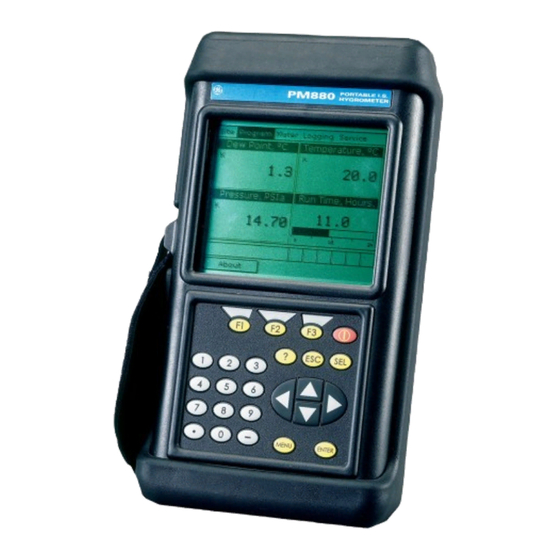
August 2003 The PM880 Hygrometer The center of the measurement system is the PM880 hygrometer. It includes a Liquid Crystal Display, a membrane keypad, menu keys, an infrared port, and a probe connection. See Figures 1-1 below and 1-2 on page 1-3. - Page 13 PC, refer to Appendix C. • To transfer files between the PM880 and PC, see Managing Files — the Drive Manager on page 5-14. • To transfer a log from the PM880 to a PC, see page 7-14. Features and Capabilities...
-
Page 14: Display And Keypad
August 2003 Display and Keypad The PM880 front panel (shown in Figure 1-1 on page 1-2) has a 240 X 200 pixel LCD display, which can show data in either alphanumeric or graphic formats. Below the display, the 25-key keypad enables users to program and operate the PM880. The functions for the various keys are discussed in Chapter 2. -
Page 15: Probes
Probes Probes are the part of the system that come into contact with the process flow. The PM880 uses various types of probes to fit the needs of a wide range of applications. The term “probe” includes devices such as moisture sensors and pressure transducers. - Page 16 The M and the TF Series probes, when operated with a BASEEFA-approved PM880, are intrinsically safe (see Chapter 10, Specifications) and designed to meet the requirements of IEC/ CENELEC zone 0 areas.
-
Page 17: Moisture Image Series Probe
The Moisture Image Series Probe, when operated with a BASEEFA-approved PM880, is intrinsically safe (see Chapter 10, Specifications, for BASEEFA certification numbers) and designed to meet the requirements of IEC/CENELEC zone 0 areas. - Page 18 August 2003 Moisture Image Series Probe (cont.) Electronics Module Figure 1-5: The Moisture Image Series Probe Features and Capabilities...
-
Page 19: Cabling
The M and the TF Series probes are connected to the analyzer with a special GE Panametrics shielded cable. Probes can be located up to 600 meters (2,000 feet) from the PM880 (consult GE Panametrics for distances up to 1,200 meters). To measure pressure with a TF probe, the maximum cable length is approximately 152 meters (500 feet). -
Page 20: The User Program
August 2003 The User Program On the PM880, users access and control the user program by pressing the Menu key at the bottom of the keypad. This program enables users to enter the necessary probe and calibration data, set up the display, log data, and perform service functions. The meter stores this data in battery-backed RAM. -
Page 21: Chapter 2: Initial Setup
August 2003 Chapter 2 Initial Setup The PM880 hygrometer typically functions as part of a complex process system. Before making measurements, you must install batteries, attach a probe, and set it up in a sample system (either a preinstalled sample system or the GE Panametrics optional portable sample system). -
Page 22: Choosing A Site
Choosing a Site You should have discussed environmental and installation factors with a GE Panametrics applications engineer or field sales person by the time you receive the PM880. The equipment should be suited to the application and installation site. •... -
Page 23: Moisture/Temperature Probe Considerations
Observing these few simple precautions will result in a long and useful probe life. GE Panametrics recommends that probe calibration be checked routinely, at 12-month intervals, or as recommended by our applications engineers for your particular application. - Page 24 August 2003 Moisture/Temperature Probe Considerations (cont.) Observe the following environmental precautions. a. Temperature Range The standard probe is operable from -110°C to +70°C (-166°F to 158°F). b. Moisture Condensation Be sure the temperature is at least 10°C higher than the dew/frost point temperature.
- Page 25 August 2003 Moisture/Temperature Probe Considerations (cont.) e. Long-Term Storage & Operational Stability Sensors are not affected by continuous abrupt humidity changes or damaged by exposure to saturation conditions even when stored. However, you should store probes in their original shipping containers in a clean, dry location. If the probe is saturated during storage, refer to b.
-
Page 26: Sample System Guidelines
They may also allow ambient contamination to enter the sample stream. In general, you should use stainless steel material for all wetted parts. Contact the GE Panametrics PCI Division at 1-800-833-9438 (within the USA) or 781-899-2719 (outside the USA) for further instructions. - Page 27 The sample system is normally fastened to a metal plate that has four mounting holes. GE Panametrics also provides the sample system in an enclosure if requested. In either case, fasten the sample system plate or enclosure with four bolts — one in each corner.
-
Page 28: Installing The Probes
Screw the probe in, making sure not to cross thread it. Tighten down securely. Figure 2-2 below shows a typical moisture probe orientation with the probe mounted in a GE Panametrics sample cell. Install moisture probes with different fittings in the appropriate manner. -
Page 29: Connecting The Probe To The Pm880
2-3 below. Probe Input Figure 2-3: Connection Locations !WARNING! To ensure the safe operation of the PM880, you must install and operate it as described in this manual. In addition, be sure to follow all applicable safety codes and regulations for installing electrical equipment in your area. -
Page 30: Charging And/Or Replacing Batteries
Charging the Batteries When you receive the PM880, you will need to initially charge the batteries. The batteries must be charged up to 4 to 5 hours to receive the maximum charge, until the red LED goes out. When fully charged, the batteries provide 16 to 24 hours of continuous operation, depending on the probe type and PM880 usage. -
Page 31: Replacing The Batteries
(GE Panametrics Part Number 705- 1023). To replace the batteries, remove the rubber boot, open the panel located on the back of the PM880, remove the battery pack, and replace it with a new pack (see Figure 2-4 below). -
Page 32: Powering On And Off
IMPORTANT: For CE compliance, the PM880 is classified as a battery-powered device. To turn the PM880 on, press the red button in the upper-right- hand corner of the keypad. Immediately upon power up the PM880 displays a “PCI Loader” message. It then validates the instrument programming, and then displays the GE Panametrics logo and the software version. - Page 33 August 2003 Powering On and Off (cont.) After the meter conducts all the self checks, the screen then appears similar to the one shown in Figure 2-5 below. 2002/11/30 09:53 AM Dew Point, °C Temperature, °C 23.0 -52.0 10 Minutes Run Time, Hours Pressure, PSIg 10.0...
- Page 34 PM880 to [F3] normal operation. If the PM880 locks up, you can reset it by holding the power key (the red key in the upper right corner) for 15 seconds. 2-14 Initial Setup...
-
Page 35: Using The Screen And Keypad
August 2003 Using the Screen and Keypad The essential features for operating the PM880 are the screen and keypad. Although these features are common on portable instruments, the PM880 design offers particular features to simplify and speed operation. Screen The primary function of the screen is to display information in order for you to accurately and easily take measurements. - Page 36 August 2003 Screen (cont). The middle of the screen shown in Figure 2-7 on page 2-15 is the work area, which displays the measured parameters, numeric measurements, and both bar and line graphs. (When you enter a selection on the Menu Bar discussed in Chapter 3, Programming Site Data, this area displays menu prompts.) A line at the bottom of the area also displays error code messages, which are described in more detail in Chapter 9, Diagnostics and Troubleshooting.
-
Page 37: Keypad
August 2003 Keypad The PM880 keypad has 25 keys. The functions for each key are as follows (see Figure 2-8 on page 2-18): • 3 function keys ( ) — enable you to select the [F1] [F2] [F3] special functions which appear at the bottom of the screen. - Page 38 August 2003 Keypad (cont.) Figure 2-8: The PM880 Keypad 2-18 Initial Setup...
-
Page 39: Obtaining On-Line Help
August 2003 Obtaining On-Line Help The PM880 offers context-sensitive on-line help screens that describe various features. You can access on-line help at any time by pressing the [?] key. The screen appears similar to Figure 2-9 below. Help Velocity, ft/s... -
Page 40: Chapter 3: Programming Site Data
Once you have entered this data, you can save it in files and recall these files for later use. The PM880 can store up to 1 MB of data in the meter at any one time. But through the infrared link, users can store an unlimited number of sites in a PC, and then upload the sites they will actually use. -
Page 41: Entering The Program Menu
[MENU] right of the PM880 keypad. The Menu Bar replaces the Status Bar at the top of the screen. Press the [ ] arrow key once to scroll from the Site Menu to the Program Menu. At the Program Menu, press . - Page 42 August 2003 When entering parameters in an option, press: • The [ ] key to step through the available parameters • The [ ] key to scroll back to a previously entered parameter • key (Cancel) or the key to exit an option at any [F2] [ESC] time and return to Operate Mode without changing the...
-
Page 43: Entering Probe Configurations
Entering Probe Configurations Although you have connected a probe cable to the top of the PM880, you must program the PM880 software for the particular probe type. In addition, if you need to use a constant value for moisture, temperature or pressure measurement (rather than a live input), you must program the PM880 for a constant value. - Page 44 When you have completed entering probe and constant information: • To confirm the entries and return to Operate Mode, press [F3] (OK). The PM880 returns to Operate Mode. • To leave the window without confirming the entries, press [F2] (Cancel) or the key.
-
Page 45: Entering Calibration Data
You only need to enter calibration data for M and TF Series probes. The Moisture Image Series probe stores calibration data in its electronics module, and uploads it into the PM880 memory when needed. It is unnecessary to enter calibration data for the Moisture Image Series probe, unless you send it back to GE Panametrics for calibration without its electronics module. -
Page 46: Entering Moisture Calibration Data
Note: To insert an additional data point, press (Insert). [F1] To delete a data point, press (Delete). [F2] 5. When you have completed entering values, press [F3] (Exit). The PM880 returns to the Hygro tab at the top of the screen. Programming Site Data... - Page 47 (if available, depending on the probe type). • To confirm the data and return to Operate Mode, press [F3] (OK). The PM880 returns to Operate Mode. • To leave the window without saving the data, press [F2] (Cancel) or the key.
-
Page 48: Entering Pressure Calibration Data
5. Use the arrow keys to move to the Span boxes, and repeat steps 3 and 4 to enter the Span values. 6. When you have completed entering values, press (Exit). [F3] The PM880 returns to the Pressure tab at the top of the screen. Programming Site Data... - Page 49 (if available, depending on probe type). • To confirm the data and return to Operate Mode, press [F3] (OK). The PM880 returns to Operate Mode. • To leave the window without saving the data, press [F2] (Cancel) or the key.
-
Page 50: Entering Saturation Constants
August 2003 Entering Saturation Constants The PM880 requires a saturation constant in order to calculate in nonaqueous liquids. (If you do not know the saturation constants of the process liquid sample, contact GE Panametrics.) To enter a saturation constant, you must enter 1 to 8 data points to represent a curve of Cs (constants) versus temperature. - Page 51 [F2] 6. When you have completed entering values, press (Exit). [F3] The PM880 returns to the Saturation tab at the top of the screen. You now have three choices: • Use the arrow keys to enter another Calibration window and program additional data (if available, depending on probe type).
-
Page 52: Entering Probe Identification Data
August 2003 Entering Probe Identification Data The Probe ID window enables you to reference identifying data for the probe calibrated in the other windows: the serial number, the most recent calibration data, and the approximate time of the next calibration. To enter, change or confirm identification data, complete the following steps: 1. - Page 53 August 2003 Entering Probe Identification Data (cont.) 4. Press the [ ] key to move to the suffix box, and press to open the drop-down list. The menu offers a choice [ENTER] of seven suffix options: • • • • •...
- Page 54 Entering Probe Identification Data (cont.) 6. The final prompt asks you to select a time period at which the screen displays a calibration reminder for the probe, determined from the last calibration date. GE Panametrics recommends recalibrating a probe annually. a. Press to open the drop-down list.
-
Page 55: Entering The System Configuration
System option, and press . The screen appears [ENTER] similar to Figure 3-7 below. Note: If you have programmed the PM880 for use with the MIS Probe, the System option is not available. System Configuration Minutes AutoCal Interval... - Page 56 Use the numeric keys to enter the desired interval (in minutes). c. Press to confirm the entry. [ENTER] 3. The PM880 now asks for the response type. Three choices are available: NORM (normal), CER (computer enhanced response), and DEF (derivative fast response). a. Press to open the drop-down menu.
-
Page 57: Entering User Functions
August 2003 Entering User Functions User functions enable you to program mathematical equations on each measurement. You can also use any parameter in the meter to calculate a different parameter. To enter the User Functions option, scroll to the User Functions entry on the Program Menu and press . - Page 58 August 2003 Entering User Functions (cont.) 2. The next prompt asks you to create a label for the function. The label corresponds to the measurement type (i.e., velocity or temperature), while the units symbol corresponds to the measurement units (i.e., feet/sec or degrees F). a.
- Page 59 August 2003 Entering User Functions (cont.) d. When you have completed the label, press (OK) to [F3] confirm the label, or (Cancel) to leave the window [F2] without adding the label. 3. The next prompt asks for the Units Symbol. a.
- Page 60 August 2003 Entering User Functions (cont.) sqrt MODE asin acos atan tblB tblC tblE tblA tblD tblF Delete Cancel Figure 3-10: The Function Creation Window c. To enter a particular measured parameter into the equation, click on the MODE symbol in the middle of the third row. The Select Measurement window (shown in Figure 3-11 on page 3-22) opens.
- Page 61 Figure 3-11: The Select Measurement Window 6. GE Panametrics recommends pressing (Check) to test the [F2] validity of the function. The PM880 displays either “OK” or a message such as “Syntax Error.” • Press to delete the entire function, or [F1] •...
-
Page 62: Chapter 4: Creating And Managing Sites
Chapter 4 Creating and Managing Sites As mentioned in Chapter 1, the PM880 can store site data in files for current and future access. (To learn how to program setup data, refer to Chapter 3, Programming Site Data.) After you answer the necessary questions, simply save the information to a site file. -
Page 63: The Site Manager
Exit Refresh Figure 4-2: The Site Manager Window Note: Each PM880 comes preprogrammed with a basic site, Default, which serves as a basis for saving data and creating other sites. The right section of the screen supplies information for the site highlighted in the list on the left: the site name, its date, time and size, as well as the remaining amount of free memory. - Page 64 To transfer a site to a PC, go to page 4-13. • To transfer a site from a PC to the PM880, go to page 4-15. You can arrange files from the Sort submenu (shown in Figure 4- 18 on page 4-18.) •...
-
Page 65: Creating A New Site
August 2003 Creating a New Site Note: Be sure you have entered the necessary setup data discussed in Chapter 3, Programming Site Data, before creating and saving a new site. To create a new site within the Site Manager, press [MENU] open the File Menu. - Page 66 August 2003 Creating a New Site (cont.) • Press (No) if you do not want to use it, or [F2] • Press (Yes) if you do want to use it as a template. [F3] New Site New Site Use the selected site ‘DEFAULT.SIT’...
-
Page 67: Opening An Existing Site
• Press (Yes) to open the site. [F3] If you have changed the current site, the PM880 asks if you want to save the changes to the previously opened site. • Press (No) to cancel the changes, or [F2] •... -
Page 68: Saving A Site
Figure 4-7: The Save Current Site Window • Press (No) to cancel saving the site, or [F2] • Press (Yes) to save the site. [F3] The PM880 remains in the current window (Operate Mode or Site Manager), with the current site saved. Creating and Managing Sites... -
Page 69: Saving A Site With A Different Name
• Press (No) to cancel saving the site, or [F2] • Press [F3] (Yes) to save the site. The PM880 remains in Site Manager, with the current site saved under both the old and new names. Creating and Managing Sites... -
Page 70: Refreshing A Site
When you have finished, • Press (Cancel) to erase the entry, or [F2] • Press , OK, to confirm the entry. [F3] The PM880 remains in Site Manager, with the site listed under the new name. Creating and Managing Sites... -
Page 71: Deleting A Site
August 2003 Deleting a Site To delete a site in the Site Manager, first be sure you have highlighted that site in the left window of the Site Manager. Then press to open the File Menu, scroll to the Delete option, [MENU] and press . -
Page 72: Creating A Site Message
August 2003 Creating a Site Message The Site Message option allows you to add an explanatory message (with up to 30 characters or spaces) for any given site. To create a site message: 1. Press to enter the File Menu. Then press the [ ] [MENU] arrow key once to scroll from the File Menu to the Site Menu. - Page 73 August 2003 Creating a Site Message (cont.) “ ‘ < > Delete Cancel Figure 4-12: The Text Creation Window 3. Use the four arrow keys to scroll to the desired letter or symbol, and press to add the letter to the message. [ENTER] Note: Pressing causes the screen to alternate between a...
-
Page 74: Printing A Current Site
Transferring a Site File to a PC To upload a site file to a PC, you must have an infrared sensor connected to the PC that can receive data from the PM880 IR beam. 1. Check that the Communications option on the PM880 (see... - Page 75 Transferring a Site to a PC (cont.) The screen shows a message indicating that the PM880 is searching for an infrared device. (If the PM880 cannot detect an infrared device, a window appears indicating this problem, and asks if you want to try again.) If it finds a device, it sends another message indicating that it is uploading the site.
-
Page 76: Transferring A File From A Pc To The Pm880
To download a site or meter file from a PC to a PM880: 1. Check that the Communications option on the PM880 (see page 6-14) has been set to the IrDA protocol, and that the IR beam on the PM880 has clear access to the IR sensor connected to the PC port. - Page 77 August 2003 Transferring a File from a PC to the PM880 (cont.) • Open the Send menu in the QuickBeam window, enter the Files or Files on Clipboard option, scroll to the desired file, and click Send. QuickBeam opens a window indicating that it is downloading the file.
- Page 78 August 2003 Transferring a File from a PC to the PM880 (cont.) • From Windows Explorer, right-click on the selected file. Select Send To Infrared Recipient or Nearby Computer. For Windows 2000, you can also drag the selected file to the Wireless Link icon, shown in Figure 4-17 below.
-
Page 79: Listing Files By Name
August 2003 Listing Files by Name If you want to list your files alphabetically by site name within the Site Manager, press to open the File Menu. Then [MENU] press the [ ] arrow key twice to scroll from the File Menu to the Sort Menu, shown in Figure 4-18 below. -
Page 80: Chapter 5: Displaying And Configuring Data
August 2003 Chapter 5 Displaying and Configuring Data The PM880 allows you to view from one to four different measurement parameters simultaneously. The screen can show these parameters not only in numeric format, but as line or bar graphs as well. -
Page 81: The Format Option
August 2003 The Format Option The first option on the menu, Format, allows you to specify the type of notation and the number of decimal places for the measurement in that window. Press and the submenu [ENTER] shows two options, Decimal Place and Notation. Press the [ ] or ] arrow keys to select either entry, and press . - Page 82 August 2003 The Format Option (cont.) 2. The second step asks you to choose the number of decimal places to be displayed. Available choices range from 0 to 4 places. a. Press to open the drop-down list. [ENTER] b. Scroll to the appropriate number. c.
-
Page 83: The View Option
August 2003 The View Option The second option, View, allows you to select the presentation of a parameter in one of three formats: numeric, bar graph or line graph 1. From the Display Menu, press the [ ] key once to reach the View option, and then press [ENTER] 2. -
Page 84: The Limits Option
August 2003 The Limits Option Once you have configured a parameter as a line or bar graph, you might need to change its presentation or values. The Limits option (replacing the Format option for line and bar graphs) enables you to program the minimum or maximum values displayed, the time interval and the display of the average value. - Page 85 August 2003 The Limits Option (cont.) 4. The first prompt asks for the minimum value shown in the graph. a. Press to open the text box. [ENTER] b. Use the numeric keys to enter the desired value. c. Press [ENTER] to confirm the value.
-
Page 86: The Measurement Option
August 2003 The Measurement Option On occasion, you might need to change the actual parameter measured in a given window.The Measurement option enables you to reconfigure the window with one of five categories of data source (hygro, temperature, pressure, battery and user function) and appropriate measurement units. - Page 87 August 2003 The Measurement Option (cont.) Select Measurement Dew Point/°C Hygro Dew Point/°F Temperature Dew Point/K Pressure Rel. Humidity ppMv Battery ppBv UserFunction ppMw MMSCF/IG MMSCF/NG No Unit Cancel Done Figure 5-5: The Select Measurement Window Displaying and Configuring Data...
-
Page 88: Customizing The Display Screen
To enter the Site Menu, press the key at the lower right [MENU] of the PM880 keypad. The Menu Bar replaces the Status Bar at the top of the screen. The Site Menu will be highlighted in the upper left corner. Press or the [ ] arrow key. -
Page 89: Specifying The Number Of Displayed Parameters
August 2003 Specifying the Number of Displayed Parameters As mentioned earlier, the PM880 can display one to four different measurement parameters simultaneously. However, sometimes you might wish to display only one or two parameters. To change the number of open display windows from within the Site Menu... -
Page 90: Customizing Softkeys
August 2003 Customizing Softkeys When the screen is in Operate Mode, you might wish to access a particular submenu frequently without the trouble of scrolling through menus. Customizing the softkeys ( [F1] [F2] [F3] allows you to access up to three submenus by pressing the associated softkey. - Page 91 August 2003 Customizing Softkeys (cont.) Configure FKey Select a menu item (Clear) Cancel Figure 5-9: The Configure FKey Window 3. Press to open the menu drop-down list. Then use the [ENTER] ] or [ ] arrow keys to scroll to the desired submenu (for example, Contrast).
- Page 92 August 2003 Customizing Softkeys (cont.) 2002/11/30 09:53 AM Temperature, °C Dew Point, °C 23.0 -52.0 10 Minutes Run Time, Hours Pressure, PSIg 10.0 55.00 Contrast Figure 5-10: The Display Screen with Modified Softkey • To clear a softkey: 1. From the Site Menu (shown in Figure 5-6 on page 5-9), use the [ ] or [ ] arrow keys to move to the FKeys entry on the...
-
Page 93: Managing Files - The Drive Manager
Managing Files — The Drive Manager On occasion, you might want to review, print, transfer or rearrange some or all of the files in the PM880. The Drive Manager allows you to view all the files stored in the meter. - Page 94 Then press to open [MENU] the File Menu, and scroll to the appropriate option, as shown in Figure 5-12 above. Press . The PM880 then performs the [ENTER] desired action with the file. Displaying and Configuring Data 5-15...
-
Page 95: Transferring A File To A Pc
1. Check that the Communications option on the PM880 (see page 6-14) has been set to the IrDA protocol, and that the IR beam on the PM880 has clear access to the IR sensor connected to the PC port. Note: For Windows NT4.0, check that the QuickBeam software (available through the path C:\Program Files\QuickBeam Suite) is running. -
Page 96: Transferring A File From A Pc To The Pm880
Note: It is not possible to download log files back to the PM880. To download a site or meter file from a PC to a PM880: 1. - Page 97 August 2003 Transferring a File from a PC to the PM880 (cont.) • Open the Send menu in the QuickBeam window, enter the Files or Files on Clipboard option, scroll to the desired file, and click Send. QuickBeam opens a window indicating that it is downloading the file.
-
Page 98: Refreshing A File
Note: While sending or receiving files, the PM880 continues to perform measurements, but at a slower rate than normal. Refreshing a File To refresh a file so that the PM880 displays the most recent information, you have two options: •... -
Page 99: Listing Files By Name
August 2003 Deleting a File (cont.) File Manager Delete Confirmation File Programming Info:DEFAULT DEFAULT Delete The Site ‘A.SIT’ Are You Sure? GLOBAL 1 View Figure 5-18: The Delete Confirmation Window • Press , No, to cancel the deletion and return to the File [F2] Manager, or •... -
Page 100: Listing Files In Chronological Order
August 2003 Listing Files by Name (cont.) File Manager File Sort By Name Info: DEFAULT:SIT DEFAULT. SYS.LOG New Site GLOBAL. By Date TABLE.MET FUNCTIO AAA.LOG BBB.LOG 09/04/02 14:51:10 CCC.LOG 5111 bytes Q.LOG 118272 bytes free Refresh Exit Figure 5-19: The Sort Submenu Listing Files in Chronological Order If you prefer to list your files chronologically by time of creation within the File Manager, press... -
Page 101: Accessing Meter Data -The About Option
Accessing Meter Data —The About Option The About option displays useful information concerning the model number and software versions of any given PM880. While the window normally appears briefly at startup, users might want to access the information for a longer period. To open the About window: •... -
Page 102: Chapter 6: Programming Meter Settings
August 2003 Chapter 6 Programming Meter Settings Along with display formats and site data, PM880 users can program global settings for the meter that suit their individual preferences. The global settings include: • English or Metric measurement units • Battery power •... -
Page 103: Entering The Meter Menu
[MENU] of the PM880 keypad. The Main Menu replaces the Status Bar at the top of the screen. Press the [ ] arrow key twice to scroll from the Site Menu to the Meter Menu. At the Meter Menu, press . -
Page 104: Selecting Measurement Units
Selecting Measurement Units The first option, Units, enables you to select either English or Metric units as global measurement units for the PM880. The selected units then become the default settings for every measurement that has the option for metric/English units. To... -
Page 105: The Battery Option
August 2003 The Battery Option The Battery option allows you to monitor the current run time and status of the internal rechargeable batteries. To open the option window: 1. From the Meter menu, scroll to the Battery entry and press . -
Page 106: Entering Date And Time
August 2003 Entering Date and Time In Operate Mode, the Status Bar displays the current date and time above the measurements in the upper right corner of the screen. The Date/Time option allows you to set the date or time, which are required for correct data logging operation. - Page 107 ] arrow keys causes the meter to scroll within the Meter Settings options. • To confirm the entries and return to Operate Mode, press [F3] (OK). The PM880 returns to Operate Mode. • To leave the window without confirming the entries, press [F2] (Cancel) or the key.
-
Page 108: Changing Date And Time Appearance
August 2003 Changing Date and Time Appearance In addition to setting the correct date and time, you can also change its presentation to suit local preferences. You can select a time display of AM/PM or 24-hour time. To alter the time and date display: 1. - Page 109 Press to confirm your entry. [ENTER] 4. The PM880 now asks you to select whether you want the time presented in a 12-hour format (for example, 11:53:23 PM) or in a 24-hour format (23:53:23). a. Press to open the drop-down menu.
- Page 110 A line at the bottom, the Date/Time, Decimal Formats, displays how the format and separator selections will appear on the screen. Pressing the [ ] arrow key returns the PM880 to the Locale tab. • To confirm the entries and return to Operate Mode, press [F3] (OK).
-
Page 111: Adjusting The Contrast
August 2003 Adjusting the Contrast For more comfortable viewing in a particular environment, the PM880 enables you to adjust the screen contrast. To adjust the screen contrast: 1. From the Meter menu, scroll to the Contrast entry and press . The Display Options window opens on the Display [ENTER] tab, as shown in Figure 6-5 below. - Page 112 August 2003 Adjusting the Contrast (cont.) • To confirm the entries and return to Operate Mode, press [F3] (OK). The PM880 returns to Operate Mode. • To leave the window without confirming the entries, press [F2] (Cancel) or the key. The PM880 returns to Operate [ESC] Mode.
-
Page 113: Setting Backlight Timeout
(about one-half second). By using the Backlight Timeout option, you can set a specified time that the PM880 backlight will remain on before turning itself off. Automatic turnoff enables the PM880 to conserve battery power. -
Page 114: Changing The Display Language
Figure 6-6: Language Change Window The meter restarts in Operate Mode in the desired language. Note: The PM880 defaults to US English. However, one or more alternate languages can be installed at any time. Consult your GE Panametrics representative or www.gepower.com/panametrics for available languages. -
Page 115: Changing Communications Parameters
Changing Communications Parameters On occasion, you might need to change the parameters by which the PM880 communicates with a PC over the wireless infrared interface. To check or change these parameters: 1. From the Meter menu, scroll to the Communications entry and press . - Page 116 IR232 virtual interface. You must use IrDA when using an IR printer or transfer application such as QuickBeam, or IR232 when using the GE Panametrics PanaView software. Use the [ ] and [ ] keys to scroll to the desired selection,...
- Page 117 • Data Bits -- 8 • To confirm the entries and return to Operate Mode, press [F3] (OK). The PM880 returns to Operate Mode. • To leave the window without confirming the entries, press [F2] (Cancel) or the key. The PM880 returns to Operate [ESC] Mode.
-
Page 118: Setting Up User Tables
August 2003 Setting Up User Tables When you program user functions (see page 3-18), you can also support them with up to six user tables of non-linear or empirical data. To program one or more user tables: 1. From the Meter menu, scroll to the User Tables entry and press . - Page 119 August 2003 Setting up User Tables (cont.) 3. The next step is to create a Table ID. a. Press to open the window. The screen now [ENTER] appears similar to Figure 6-9 below. UserTable1 “ ‘ < > Cancel Delete Figure 6-9: The Text Creation Window b.
- Page 120 August 2003 Setting up User Tables (cont.) Note: It is not necessary to enter the “#Data Points” or “Max Points” text boxes. 4. The final prompt asks you to enter or change data in the user table. a. Press [ENTER] to open the window.
- Page 121 The program returns to the Edit Tables window. • To confirm the entries and return to Operate Mode, press [F3] (OK). The PM880 returns to Operate Mode. • To leave the window without confirming the entries, press [F2] (Cancel) or the key.
-
Page 122: Taking A Bitmap Capture Of A Current Screen
The program now varies, depending on whether you selected printer or file capture. • If you selected To Printer, the PM880 shows a message indicating that its infrared sensor is looking for a receiving printer. (If the sensor spots no printer, a window appears indicating that it cannot find a device. -
Page 123: Chapter 7: Logging Data
Chapter 7 Logging Data A powerful and flexible feature of the PM880 is data logging. The meter enables you to choose up to 12 parameters to log. You can also select the start time and date, end time and date, and time interval. -
Page 124: Entering The Logging Menu
[MENU] right of the PM880 keypad. The Main Menu replaces the Status Bar at the top of the screen. Press the [ ] arrow key three times to scroll from the Site Menu to the Logging Menu. At the Logging Menu, press . -
Page 125: The Log Manager
August 2003 The Log Manager The Log Manager offers users a way to check the status and memory size of all the logs currently pending, running or finished. To select Log Manager, scroll to the Log Manager entry on the Logging Menu and press [ENTER] . -
Page 126: The File Menu
August 2003 The File Menu The File Menu allows you, not only to create new logs, but also to copy, rename or delete logs, as well as to print them or transfer them to a PC. To open the File Menu from the Log Manager, press the [MENU] key and then... -
Page 127: Setting Up A New Log
, OK, to confirm the entry. [F3] Create New Log & Cancel Delete Figure 7-4: The New Log Window The PM880 now asks for log formatting and measurements. The screen appears similar to Figure 7-5 on page 7-6. Logging Data... - Page 128 August 2003 Setting up a New Log (cont.) Measurements General Log Name 10SEC.LOG Format Circular Linear Type Error Standard Start Date/Time 01:38:08 2000/11/01 09:38:08 End Date/Time 2000/11/01 Logging Interval secs Activate Cancel Figure 7-5: The General Log Format Window To step through each parameter, press the [ ] key. 1.
- Page 129 August 2003 Setting up a New Log (cont.) a. Press [ENTER] to enter the text box. The meter highlights the first number. Use the [ ] and [ ] keys to scroll to any number you wish to change, or the [ ] key to scroll to the time box.
- Page 130 August 2003 Setting up a New Log (cont.) General Measurements NO UNIT NO UNIT NO UNIT NO UNIT NO UNIT NO UNIT NO UNIT NO UNIT NO UNIT NO UNIT NO UNIT NO UNIT Activate Cancel Figure 7-6: The Log Measurements Window To step through each entry, press the [ ] key.
- Page 131 (Activate) to confirm the entries and start the log. If you started the log from the New Log option, the PM880 returns to Operate Mode, with a Pencil icon in the System Tray; if you started it from within the Log Manager, the meter returns to the Log Manager.
-
Page 132: Copying (Cloning) A Selected Log
6. When you have completed modifying the log parameters, press (Cancel) to cancel the log or (Activate) to [F2] [F3] confirm and start the new log. The PM880 returns to the Log Manager, which now displays the status of the cloned log. 7-10 Logging Data... -
Page 133: Renaming A Log
7-6 to create a log name, and press (OK) to confirm [F3] the name. The PM880 returns to the Log Manager, which highlights the renamed log. Deleting a Log To delete a log: 1. First, select the log you wish to delete in the Log Manager (shown in Figure 7-2 on page 7-4). -
Page 134: Deleting All Logs
August 2003 Deleting a Log (cont.) Log Manager Delete File Programming Info:DEFAULT DEFAULT Delete Log ‘555.LOG?’ GLOBAL 1 View Figure 7-8: The Delete Confirmation Window Deleting All Logs To clear the Log Manager and memory of all logs, open the File menu, scroll to the Delete All Logs option, and press [ENTER] window opens, asking, “Delete All Logs?”... -
Page 135: Printing A Log
August 2003 Printing a Log To print a file from the Log Manager: 1. Highlight the desired log in the window on the left of the Log Manager. 2. Press , scroll to the Print option, and press [MENU] [ENTER] 3. -
Page 136: Transferring A Log To A Pc
(If the sensor spots no printer, a window appears with this message. If it spots two printers within its range, it asks you to select the desired device.) If successful, the PM880 returns to the Log Manager, while the printer prints out the log. -
Page 137: The Log Menu
August 2003 The Log Menu The Log Menu allows you to pause, restart or end any or all logs that are currently pending or running. (However, you cannot restart any finished logs, even if they were finished before the programmed end time.) To open the Log Menu in the Log Manager, press . -
Page 138: Stopping (Pausing) A Log
(shown in Figure 7-2 on page 7-4). 2. Then open the Log Menu, scroll to the Pause option, and press [ENTER] The PM880 returns to the Log Manager, which displays the highlighted log with “Paused” in the State line. Restarting a Log To restart a paused log: 1. -
Page 139: Stopping All Logs
[ENTER] in use at the time the log is created. Thus, when another site is in use, the PM880 automatically starts different logs. By default, the Log Manager only displays the logs created with the current site. View All Sites allows the Manager to list logs for all sites. -
Page 140: The View Menu
August 2003 The View Menu Through the View menu, you can view the data of individual logs in graphical or spreadsheet formats. To open the View menu from the Log Manager, press . Scroll to the View menu, and [MENU] press [ENTER] . -
Page 141: Displaying Log Details
August 2003 Displaying Log Details To view details of a given log, be sure the log is highlighted in the left window of the Log Manager. Then scroll to the View menu and press . Scroll to the Details option and press [ENTER] . -
Page 142: Displaying Log Data In Graphical Form
August 2003 Displaying Log Data in Graphical Form To view a log in graphical form, be sure the log is highlighted in the left window of the Log Manager. Then scroll to the View menu and press . Scroll to the Graph option and press [ENTER] [ENTER] AAA.LOG (Dew Point, °C) - Page 143 [ENTER] If you select Max or Range for limits, you have finished entering data in this form. But if you select Set, the PM880 asks for minimum and maximum limits. 2. Press the [ ] key to reach the Minimum text box.
- Page 144 August 2003 Displaying Log Data in Graphical Form (cont.) If you wish to alter the time scale, press [F2] (Time). The Enter Time window appears similar to Figure 7-15 below. AAA.LOG (Dew Point, °C) -52.0 Enter Time Start Date Start Time 2003/03/01 13:23:41 PM End Date...
-
Page 145: Displaying Log Data In Spreadsheet Form
August 2003 Displaying Log Data in Spreadsheet Form To view a log in spreadsheet form, be sure the log is highlighted in the left window of the Log Manager. Then scroll to the View menu and press . Scroll to the Spreadsheet option and [ENTER] press . -
Page 146: The Sort Menu
August 2003 The Sort Menu The Sort Menu within the Log Manager allows you to arrange your log list either alphabetically (By Name) or chronologically (By Date). Log Manager Sort File View By Name Info: AAA.LOG State: Finished By Date S:03/01/01 13:13:41 E:03/01/01 13:23:41 Interval: 10 Seconds... -
Page 147: Chapter 8: Servicing The Pm880
August 2003 Chapter 8 Servicing the PM880 For user convenience, the PM880 offers a Service Menu. This menu enables users to perform a variety of functions that they might occasionally require: • print out reports • test the PM880 screen and keys •... -
Page 148: Entering The Service Menu
[MENU] right of the PM880 keypad. The Menu Bar replaces the Status Bar at the top of the screen. Press the [ ] arrow key four times to scroll from the Site Menu to the Service Menu. At the Service Menu, press . -
Page 149: Printing Reports
August 2003 Printing Reports When used with an IR-compatible printer, the PM880 can print out a variety of data (current site, logs, drive contents, and user functions, tables, and settings) in the Reports option. To enter the Reports option, scroll to the Reports entry on the Service Menu and press . - Page 150 August 2003 Printing Reports (cont.) Figure 8-3: Printout of a Typical Drive Report Servicing the PM880...
-
Page 151: Testing The Screen, Keys And Meter
Testing the Screen, Keys and Meter Within the Service Menu, the Test option includes three tests to ensure that the PM880 is performing properly: Test Screen, Test Keys, and the Watchdog Test. To enter this option, scroll to the Test entry on the Service Menu and press [ENTER] . -
Page 152: Testing The Screen
August 2003 Testing the Screen To test the proper functioning of the PM880 screen, scroll to the Test Screen option in the Test Menu and press . The [ENTER] screen then shows the message, “Press Any Key To Continue.” Once you press a key, a screen with a checkerboard pattern appears, as shown in Figure 8-5 below. -
Page 153: Testing The Keys
Figure 8-6: The Test Keys Window Pressing the key returns the meter to the Operate Mode. If [F3] any key does not appear on the screen, contact GE Panametrics. Note: The power key does not appear. Servicing the PM880... -
Page 154: Testing The Watchdog Timer Circuit
August 2003 Testing the Watchdog Timer Circuit The PM880 includes a watchdog timer circuit. If a software error causes the meter to stop responding, this circuit automatically resets the meter. A properly functioning PM880 restarts if you run the Watchdog Test. -
Page 155: Entering Reference Data
Entering Reference Data IMPORTANT: Do not change these values without consulting GE Panametrics. The PM880 requires reference values for its measurement circuitry for moisture and pressure inputs. The references are factory calibration values. (Please contact GE Panametrics for more information.) To enter the option, scroll down to the References entry in the Service Menu and press . -
Page 156: Entering Pressure Reference Values
• To confirm the reference data and return to Operate mode, press (OK). The PM880 returns to Operate Mode. [F3] • To leave the window without confirming the data, press... -
Page 157: Resetting To Factory Default Parameters
August 2003 Resetting to Factory Default Parameters For various reasons, you might wish to return the PM880 to its original settings. The Factory Defaults option enables you to return the meter to its preprogrammed default settings. To enter the option, scroll down to the Factory Defaults entry in the Service Menu and press . -
Page 158: Updating Pm880 Software
The updating procedure involves three steps: 1. Setting up the PM880 in Flash Update mode. 2. Selecting the loading interface. 3. Loading the new software from the PC into the PM880. Caution! To guard against mishap, you should print out, download or otherwise record all logs, settings and other data you wish to save. -
Page 159: Updating Software Via Irobex
4. The meter asks for confirmation. Again, press (Cancel) to [F2] return to Operate Mode or (OK) to continue with the [F3] update. After the PM880 reboots, the screen appears similar to Figure 8-12 below. Panametrics PCI Loader v3.0 2/26/02 [HW Rev3+] Backup Battery: OK... - Page 160 QuickBeam has been installed). • Open the Infrared Transfer Application (My Computer\Infrared Recipient), click on Send Files, and select the files you wish to send. In either case, a window displays the status of the file upload. 8-14 Servicing the PM880...
-
Page 161: Updating Software Via Ircomm
Infrared Monitor in the Control Panel and clicking on the Options tab. It displays the message, “Providing Application Support on:” and then lists the virtual infrared port, as shown in Figure 8-13 on the next page. Servicing the PM880 8-15... - Page 162 Service Menu and press . The screen [ENTER] appears similar to Figure 8-14 below. Update Flash --WARNING-- This will erase the instrumentation coding. Choose ‘Cancel’ to exit or ‘OK’ to continue. Cancel Figure 8-14: The Flash Update Option 8-16 Servicing the PM880...
- Page 163 (OK) to confirm that you wish to erase the program. 2. The meter asks for confirmation. Repeat the options shown in Step 1 above. The screen on both the PC and the PM880 now appears similar to Figure 8-15 below. Panametrics PCI Loader v3.0...
- Page 164 3. From the Protocol drop-down menu, select Xmodem. 4. Click Send. For a successful transfer, the PC window appears similar to Figure 8-17 below, while the PM880 screen displays the program ID, size, load address and a count of blocks being loaded.
-
Page 165: Viewing Or Changing Security Settings
For both the User and Operator level, the default code is 2719. The PM880 maintains a record of the current security level. If a user attempts to access a menu that requires a higher security level, a screen (shown in Figure 8-18 on the next page) prompts for the appropriate passcode, which must be at the appropriate (or higher) level. -
Page 166: Checking Security Levels And Remote Access Security
Security Settings entry in the Service Menu and press . The screen appears similar to Figure 8-19 below. [ENTER] Security Settings Level Passwords Passwords Security Level Service Allow PanaLink Access Allow File Receive Allow File Transmit Cancel Figure 8-19: Security Level Window 8-20 Servicing the PM880... - Page 167 [ENTER] 2. The following three prompts control three separate remote access security settings: PanaLink remote access to the PM880, receiving files from a PC via IrDA, and transmitting files to a PC via IrDA. a. Scroll to the desired setting.
-
Page 168: Viewing Or Changing The Security Passcodes
(Cancel) to return to Operate Mode without [F2] changing the current passcode. • Press [F3] (OK) to confirm the changes and return to Operate Mode. Note: If your passcodes are no longer available, contact GE Panametrics. 8-22 Servicing the PM880... -
Page 169: Chapter 9: Diagnostics And Troubleshooting
August 2003 Chapter 9 Diagnostics and Troubleshooting The PM880 is designed to be maintenance and trouble-free; however, because of process conditions and other factors, minor problems may occur. Some of the most common problems and procedures are discussed in this chapter. If you cannot find the information you need in this chapter, please consult GE Panametrics. -
Page 170: Error Code Messages
The Error Code messages are only general descriptions of the possible problems. Use Table 9-1 on page 9-3 to isolate and remedy the problem. If you are unable to remedy the problem, contact GE Panametrics. Diagnosis and Troubleshooting... - Page 171 A probe of type Connect the required required has not probe. been installed. Err 2: Out of A calculated result Contact GE Panametrics. exceeds the unit’s Range capacity. Err 3: Over Range A calculated result Contact GE Panametrics. exceeds the unit’s Change the measurement calibration range.
- Page 172 Auto- Cal, or a probe fail- ure is interfering with AutoCal. Err 25: No Data The MIS Probe has The PM880 will try to not responded, or a send data; wait for next calculation is not yet update. complete.
-
Page 173: Common Problems
August 2003 Common Problems If the PM880 measurement readings seem strange, or they do not make sense, there may be a problem with the probe or a component of the process system. Table 9-2 below contains some of the most common measurement problems. - Page 174 Aluminum cles (refer to Appendix Oxide Probe Maintenance on page A-9 in Appendix A. Then rein- stall sensor. Improper cable connec- Check the cable connections to both tion. the probe and the PM880. Diagnosis and Troubleshooting...
- Page 175 Improper cable Check the cable connections to both connection. the probe and the PM880. Symptom: Slow response. Slow outgassing of Replace the system components with system. stainless steel or electro-polished stainless steel.
-
Page 176: Chapter 10: Specifications
August 2003 Chapter 10 Specifications This section contains specifications for the following: • Overall • Electronics • Operational • Moisture Measurement • Dew/frost Point Temperature • Temperature Measurement • Pressure Measurement • Sample System • Available Options Specifications 10-1... -
Page 177: Overall
August 2003 Overall Hardware Configuration Channel Options: Single channel Dimensions 238 × 138 × 38 mm Size: (9.4 × 5.5 × 1.5 inches) Weight, electronics: 1.13 kg (2.5 lb) Weight, sample system: 1.8 kg (4 lb) Electronics Internal Batteries Type: Rechargeable batteries. - Page 178 Cable type dependent on probe type: M Series, TF Series, or Moisture Image® Series. LEMO-to-bayonet connector. Cable Length: Standard: 3 m (10 ft) Optional: Consult GE Panametrics. Hazardous Area Classification: Intrinsic-safety certification pending. EECS EEx ia IIC T3 Specifications 10-3...
-
Page 179: Operational Specifications
Pressure: psig, bar, kPa (gage), kg/cm (gage) and others Moisture Measurement Compatibility: Compatible with all GE Panametrics aluminum-oxide moisture probes: M Series, TF Series and Moisture Image Series. Each probe type requires a different type of I/O cable. Calibration: GE Panametrics moisture sensors are computer calibrated to NIST-traceable moisure concentrations. -
Page 180: Dew/Frost Point Temperature
Operating Pressure: 5 µ of Hg to 5,000 psig (limited by pressure sensor — see pressure measurement specifications) Temperature Measurement Note: An optional thermistor is available for all GE Panametrics moisture probes. Range: -30°C to 70°C Accuracy: ±0.5°C at -30°C... -
Page 181: Pressure Measurement
August 2003 Pressure Measurement Note: An optional pressure sensor is available for TF Series and Moisture Image Series moisture probes. Ranges: 30 to 300 psig 50 to 500 psig 100 to 1,000 psig 300 to 3,000 psig 500 to 5,000 psig Accuracy: ±0.5% at full scale Proof Pressure:... -
Page 182: Available Options
August 2003 Available Options PC Infrared Adapter Infrared adapter connects to serial port of desktop or laptop PCs to add infrared capability. Portable Infrared Thermal Printer Portable infrared, thermal printer with rechargeable battery and 120 to 240-VAC battery charger. 160 × 164 × 59 mm (6.3 × 6.5 × 2.3 in.) Dimensions: Weight: 370 g (13 oz) -
Page 183: Appendix A: Application Of The Hygrometer
4/9/98 Appendix A Application of the Hygrometer This appendix contains general information about moisture monitoring techniques. System contaminants, moisture probe maintenance, process applications and other considerations for ensuring accurate moisture measurements are discussed. The following specific topics are covered: • Moisture Monitor Hints [page A-2] •... -
Page 184: Moisture Monitor Hints
One of the major advantages of the GE Panametrics hygrometer is that it can be used for in situ measurements (i.e. the sensor element is designed for installation directly within the region to be measured). - Page 185 • the dew point changes as the fluid flow rate changes. GE Panametrics hygrometers measure only water vapor pressure. In addition, the instrument has a very rapid response time and it is not affected by changes in fluid temperature or fluid flow rate. If any of the above situations occur, then they are almost always caused by a defect in the sample system.
-
Page 186: Pressure
4/9/98 Pressure GE Panametrics hygrometers can accurately measure dew points under pressure conditions ranging from vacuums as low as a few microns of mercury up to pressures of 5000 psig. The calibration data supplied with the moisture probe is directly applicable over this entire pressure range, without correction. -
Page 187: Response Time
4/9/98 Response Time The response time of the GE Panametrics standard M Series Aluminum Oxide Moisture Sensor is very rapid - a step change of 63% in moisture concentration will be observed in approximately 5 seconds. Thus, the observed response time to moisture changes is, in general, limited by the response time of the sample system as a whole. -
Page 188: Flow Rate
4/9/98 Flow Rate GE Panametrics hygrometers are unaffected by the fluid flow rate. The moisture probe is not a mass sensor but responds only to water vapor pressure. The moisture probe will operate accurately under both static and dynamic fluid flow conditions. In fact, the... -
Page 189: Contaminants
For convenience, the above particulates have been divided into three broad categories. Refer to the appropriate section for a discussion of their affect on the GE Panametrics moisture probe. Non-Conductive Particulates Note: Molecular sieve particles, organic liquid droplets and oil droplets are typical of this category. -
Page 190: Conductive Particulates
4/9/98 Non-Conductive Particulates (cont.) On rare occasions, non-conductive particulate material may become lodged under the contact arm of the sensor, creating an open circuit. If this condition is suspected, refer to the Probe Cleaning Procedure section of this appendix for the recommended cleaning procedure. -
Page 191: Aluminum Oxide Probe Maintenance
4/9/98 Aluminum Oxide Probe Maintenance Other than periodic calibration checks, little or no routine moisture probe maintenance is required. However, as discussed in the previous section, any electrically conductive contaminant trapped on the aluminum oxide sensor will cause inaccurate moisture measurements. If such a situation develops, return of the moisture probe to the factory for analysis and recalibration is recommended. - Page 192 Probes which are not in proper calibration must be recalibrated. It is recommended that all moisture probes be recalibrated by GE Panametrics approximately once a year, regardless of the probe’s condition.
-
Page 193: Corrosive Gases And Liquids
4/9/98 Corrosive Gases And Liquids GE Panametrics M Series Aluminum Oxide Moisture Sensors have been designed to minimize the affect of corrosive gases and liquids. As indicated in the Materials of Construction section of this appendix, no copper, solder or epoxy is used in the construction of these sensors. -
Page 194: Materials Of Construction
4/9/98 Materials of Construction M1 and M2 Sensors: Sensor Element: 99.99% aluminum, aluminum oxide, gold, Nichrome, A6 Back Wire: 316 stainless steel Contact Wire: gold, 304 stainless steel Front Wire: 316 stainless steel Support: Glass (Corning 9010) Electrical Connector: Pins: Al 152 Alloy (52% Ni) Glass: Corning 9010... -
Page 195: Calculations And Useful Formulas In Gas Applications
0°C. GE Panametrics moisture probes are never calibrated with supercooled water. Caution is advised when comparing dew points measured with a GE Panametrics hygrometer to those measured with a mirror type hygrometer, since such instruments may provide the dew points of supercooled water. -
Page 196: Nomenclature
To compute the moisture content for any ideal gas at a given pressure, refer to Figure A-1. Using a straightedge, connect the dew point (as measured with the GE Panametrics’ Hygrometer) with the known system pressure. Read the moisture content in where the straightedge crosses the moisture content scale. -
Page 197: Parts Per Million By Weight
4/9/98 Parts per Million by Volume (cont.) 2. Find the expected dew/frost point for a helium gas stream having a measured moisture content of 1000 PPM and a system pressure of 0.52 atm. Solution: In Figure A-1, connect 1000 PPM on the Moisture Content scale with 0.52 atm on the Pressure scale. -
Page 198: Weight Of Water Per Unit Volume Of Carrier Gas
4/9/98 Weight of Water per Unit Volume of Carrier Gas Three units of measure are commonly used in the gas industry to express the weight of water per unit volume of carrier gas. They all represent a vapor density and are derivable from the vapor pressure of water and the Perfect Gas Laws. - Page 199 4/9/98 Table A-1: Vapor Pressure of Water Note: If the dew/frost point is known, the table will yield the partial water vapor pressure (P ) in mm of Hg. If the ambient or actual gas temperature is known, the table will yield the saturated water vapor pressure (P ) in mm of Hg.
- Page 200 4/9/98 Table A-1: Vapor Pressure of Water (cont.) Water Vapor Pressure Over Ice (cont.) Temp. (°C) 0.776 0.761 0.747 0.733 0.719 0.854 0.838 0.822 0.806 0.791 0.939 0.921 0.904 0.887 0.870 1.031 1.012 0.993 0.975 0.956 1.132 1.111 1.091 1.070 1.051 1.241 1.219...
- Page 201 4/9/98 Table A-1: Vapor Pressure of Water (cont.) Aqueous Vapor Pressure Over Water Temp. (°C) 4.579 4.647 4.715 4.785 4.855 4.926 4.998 5.070 5.144 5.219 5.294 5.370 5.447 5.525 5.605 5.685 5.766 5.848 5.931 6.015 6.101 6.187 6.274 6.363 6.453 6.543 6.635 6.728...
- Page 202 4/9/98 Table A-1: Vapor Pressure of Water (cont.) Aqueous Vapor Pressure Over Water (cont.) Temp. (°C) 23.756 24.039 24.326 24.617 24.912 25.209 25.509 25.812 26.117 26.426 26.739 27.055 27.374 27.696 28.021 28.349 28.680 29.015 29.354 29.697 30.043 30.392 30.745 31.102 31.461 31.824 32.191...
- Page 203 4/9/98 Table A-1: Vapor Pressure of Water (cont.) Aqueous Vapor Pressure Over Water (cont.) Temp. (°C) 92.51 93.50 94.40 95.30 96.30 97.20 98.20 99.10 100.10 101.10 102.09 103.10 104.10 105.10 106.20 107.20 108.20 109.30 110.40 111.40 112.51 113.60 114.70 115.80 116.90 118.04 119.10...
- Page 204 4/9/98 Table A-1: Vapor Pressure of Water (cont.) Aqueous Vapor Pressure Over Water (cont.) Temp. (°C) 289.10 291.50 294.00 296.40 298.80 301.40 303.80 306.40 308.90 311.40 314.10 316.60 319.20 322.00 324.60 327.30 330.00 332.80 335.60 338.20 341.00 343.80 346.60 349.40 352.20 355.10 358.00...
- Page 205 4/9/98 Table A-2: Maximum Gas Flow Rates Based on the physical characteristics of air at a temperature of 77°F and a pressure of 1 atm, the following flow rates will produce the maximum allowable gas stream linear velocity of 10,000 cm/sec in the corresponding pipe sizes.
- Page 206 4/9/98 Table A-3: Maximum Liquid Flow Rates Based on the physical characteristics of benzene at a temperature of 77°F, the following flow rates will produce the maximum allowable fluid linear velocity of 10 cm/sec in the corresponding pipe sizes. Inside Pipe Flow Rate Flow Rate Diameter (in.)
- Page 207 4/9/98 10,000 1,000 8,000 10,000 6,000 8,000 5,000 6,000 4,000 5,000 3,000 4,000 3,000 2,000 2,000 1,500 1,000 1,000 10.0 -100 -110 -120 -130 Figure A-1: Moisture Content Nomograph for Gases Application of the Hygrometer (900-901D1) A-25...
- Page 208 • the calculations described in this appendix • calculations performed with the slide rule device that is provided with each GE Panametrics hygrometer • values determined from tabulated vapor pressures For comparison purposes, examples of all three procedures are listed in Table A-4.
-
Page 209: Liquid Applications
As discussed above, a GE Panametrics aluminum oxide sensor can be directly immersed in a hydrocarbon liquid to measure the equivalent dew point. - Page 210 4/9/98 Henry’s Law Type Analysis (cont.) For liquids in which a Henry’s Law type analysis is applicable, the parts per million by weight of water in the organic liquid is equal to the partial pressure of water vapor times a constant: ×...
- Page 211 • the saturation water concentration at the measurement temperature • the dew point, as measured with the GE Panametrics hygrometer Complete the following steps to determine the moisture content from the nomograph: 1. Using a straightedge on the two scales on the right of the figure, connect the known saturation concentration (PPM with the measurement temperature (°C).
- Page 212 Note: The Karl Fischer analysis involves titrating the test sample against a special Karl Fischer reagent until an endpoint is reached. 1. Measure the dew point of the known sample with the GE Panametrics hygrometer. 2. Measure the temperature (°C) of the test solution.
- Page 213 Typical Problems 1. Find the moisture content in benzene, at an ambient temperature of 30°C, if a dew point of 0°C is measured with the GE Panametrics hygrometer. a. From the literature, it is found that C for benzene at a temperature of 30°C is 870 PPM...
- Page 214 4. Find the moisture content in an unknown organic liquid, at an ambient temperature of 50°C, if a dew point of 10°C is measured with the GE Panametrics hygrometer. a. Either perform a Karl Fischer analysis on a sample of the liquid or obtain a dry sample of the liquid.
- Page 215 For such applications, the saturation value for the liquid need not be known. The GE Panametrics hygrometer can be used directly to determine the dew point, and then the percent saturation can be...
-
Page 216: Empirical Calibrations
4/9/98 Empirical Calibrations For those liquids in which a Henry’s Law type analysis is not applicable, the absolute moisture content is best determined by empirical calibration. A Henry’s Law type analysis is generally not applicable for the following classes of liquids: •... - Page 217 4/9/98 A. Instructions for Karl Fischer Analysis To perform a Karl Fisher analysis, use the apparatus in Figure A-3 and complete the following steps: 1. Fill the glass bottle completely with the sample liquid. 2. Close both valves and turn on the magnetic stirrer. 3.
- Page 218 4/9/98 B. Instructions for Preparing Known Samples Note: This procedure is only for liquids that are highly miscible with water. Excessive equilibrium times would be required with less miscible liquids. To prepare samples of known moisture content, use the apparatus in Figure A-3 and complete the following steps: 1.
- Page 219 C. Additional Notes for Liquid Applications In addition to the topics already discussed, the following general application notes pertain to the use of GE Panametrics moisture probes in liquid applications: 1. All M Series Aluminum Oxide Moisture Sensors can be used in either the gas phase or the liquid phase.
- Page 220 4/9/98 1,000 2000 1500 1000 10.0 .015 .009 .008 .007 .006 .005 Figure A-2: Moisture Content Nomograph for Liquids A-38 Application of the Hygrometer (900-901D1)
- Page 221 4/9/98 Stainless Steel Tubing (soft soldered to cover) 3/4-26 THD Female (soft soldered to cover) M2 Probe Rubber Septum Exhaust Soft Solder Metal Cover with Teflon Washer Glass Bottle Liquid Magnetic Stirrer Bar Magnetic Stirrer Figure A-3: Moisture Content Test Apparatus Application of the Hygrometer (900-901D1) A-39...
-
Page 222: Solids Applications
4/9/98 Solids Applications A. In-Line Measurements GE Panametrics moisture probes may be installed in-line to continuously monitor the drying process of a solid. Install one sensor at the process system inlet to monitor the moisture content of the drying gas and install a second sensor at the process system outlet to monitor the moisture content of the discharged gas. - Page 223 If in-line measurements are not practical, then there are two possible laboratory procedures: 1. The unique ability of the GE Panametrics sensor to determine the moisture content of a liquid can be used as follows: a. Using the apparatus shown in Figure A-3, dissolve a known amount of the solids sample in a suitable hydrocarbon liquid.
- Page 224 4/9/98 B. Laboratory Procedures (cont.) 2. An alternative technique involves driving the moisture from the solids sample by heating: a. The evaporated moisture is directed into a chamber of known volume, which contains a calibrated moisture sensor. b. Convert the measured dew point of the chamber into a water vapor pressure, as discussed earlier in this appendix.
-
Page 225: Appendix B: Menu Maps
August 2003 Appendix B Menu Maps Menu Service Program Meter Logging Site See Figure See Figure Figure Figure Figure B-2 Figure B-1: The Main Menu Menu Maps... - Page 226 August 2003 Menu Site Fkeys Manager Save About 1 View 2 Views 3 Views 4 Views Clear Clear Clear Site File Sort Menu Item Message Transfer Name Date Print Drive Manager Sort File Date Transfer Refresh Delete Name File Refresh Save Save Rename Delete...
- Page 227 August 2003 Menu Program User Probe System Calibrate Functions AutoCal Interval K X PPMv MISP None Function Saturation Hygro Pressure Probe Response Zero FP Temp C Serial Number User1 User2 User3 User4 MH (FH) Hygro Constant Zero kPa Calibrated On Dew Point Norm Cer Temperature Constant...
- Page 228 August 2003 Note: Press [F2] (Cancel) to cancel Menu the entries and return to Menu. Press [F3] (OK) to confirm the entries Meter and return to Menu. Snapshot User Tables Communications Date/Time Contrast Backlight Language Units Battery Locale Table Date Backlight Time Printer...
- Page 229 August 2003 Menu Note: Press [F2] (Cancel) to cancel Logging the entries and return to Menu. Press [F3] (OK) to confirm the entries and return to Menu. Log Manager New Log Name Format File Sort View Linear Circular Date Type Name Details Graph Spreadsheet Standard...
- Page 230 August 2003 Menu Note: Press [F2] (Cancel) to cancel entries and return to Menu. Press [F3] (OK) to confirm entries and return to Menu. Service Factory Security Factory Flash Reports Test References MIS Probe Defaults Settings Calibration Update (Factory Use (Factory Use Only) Only)
-
Page 231: Appendix C: Establishing Ir Communications With The Pm880
IR port (available on most laptops) or an IR dongle (IR to RS232 adapter for PCs without a built-in IR port). If your PC does not have an IR dongle, GE Panametrics recommends the ActiSys ACT-IR220L+ infrared to RS-232 adapter, which has been tested for compatibility with the PM880. -
Page 232: Windows 2000/Xp
Note: In some instances, the infrared port must be enabled in the BIOS of your PC. Consult your computer documentation, manufacturer or MIS department. Assistance is also available from the Microsoft Support Knowledge Base at http://support.microsoft.com. Establishing IR Communications with the PM880... - Page 233 August 2003 Index About Option......... . . 5-22 ActiSys ACT-IR220L+ infrared adapter .
- Page 234 August 2003 Index (cont.) Cables Installation Restrictions ....... . . 2-2 M Series Probe .
- Page 235 August 2003 Index (cont.) Data Sources, Changing ....... 5-7, 5-8 Date and Time Options .
- Page 236 Changing Parameters ........6-14 Establishing with PM880 ....... C-1 File Transfer .
- Page 237 August 2003 Index (cont.) K × PPMv ..........3-17 Keypad Description .
- Page 238 August 2003 Index (cont.) Language Option ........6-13 Language, Changing .
- Page 239 August 2003 Index (cont.) M Series Probe Cables ..........1-9 Description of .
- Page 240 PM880, Features of ........
- Page 241 August 2003 Index (cont.) Reference Data, Entering ........8-9 Refreshing a Site .
- Page 242 August 2003 Index (cont.) Sample System Description of ......... 2-6 Saturation Constants, Entering .
- Page 243 August 2003 Index (cont.) T Sensor Constant ........3-17 T System Constant .
- Page 244 Waltham, MA 02453 U.S.A. as the manufacturer, declare under our sole responsibility that the product Model PM880 Portable Hygrometer to which this document relates, in accordance with the provisions of ATEX Directive 94/9/EC Annex II, meets the following specifications: II 1 G EEx ia IIC T3 (-20°C to +50°C)
- Page 245 Shannon, Co. Clare Ireland declare under our sole responsibility that the Model PM880 Portable Moisture Monitor Moisture Monitor Series 35IS Portable Analyzer to which this declaration relates, are in conformity with the following standards: • EN 61326:1998, Class A, Annex C, Continuous Unmonitored Operation following the provisions of the 89/336/EEC EMC Directive.
- Page 246 Shannon, Co. Clare Ireland déclarons sous notre propre responsabilité que les Model PM880 Portable Moisture Monitor Moisture Monitor Series 35IS Portable Analyzer rélatif á cette déclaration, sont en conformité avec les documents suivants: • EN 61326:1998, Class A, Annex C, Continuous Unmonitored Operation suivant les régles de la Directive de Compatibilité...
- Page 247 Shannon Industrial Estate Shannon, Co. Clare Ireland erklären, in alleiniger Verantwortung, daß die Produkte Model PM880 Portable Moisture Monitor Moisture Monitor Series 35IS Portable Analyzer folgende Normen erfüllen: • EN 61326:1998, Class A, Annex C, Continuous Unmonitored Operation gemäß den Europäischen Richtlinien, EMV-Richtlinie Nr.: 89/336/EWG.
- Page 248 WORLDWIDE OFFICES MAIN OFFICES: GE PANAMETRICS INTERNATIONAL OFFICES: Australia Japan GE Panametrics P.O. Box 234 2F, Sumitomo Bldg. 221 Crescent St., Suite 1 Gymea N.S.W. 2227 5-41-10, Koishikawa, Bunkyo-Ku Waltham, MA 02453-3497 Australia Tokyo 112-0002 Telephone 61 (02) 9525 4055...
- Page 249 GE Panametrics 221 Crescent Street, Suite 1 Waltham, MA 02453-3497 Telephone: (781) 899-2719 Toll-free: (800) 833-9438 Fax: (781) 894-8582 E-Mail: panametrics@ps.ge.com Web: www.gepower.com/panametrics Ireland GE Panametrics Shannon Industrial Estate Shannon, County Clare Ireland Telephone: 353-61-470200 Fax: 353-61-471359 E-Mail: info@panametrics.ie...