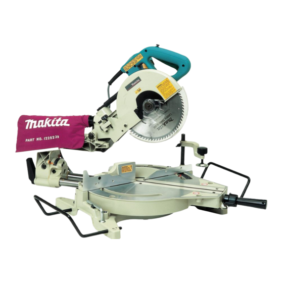
Makita LS1013 Instruction Manual
Slide compound saw
Hide thumbs
Also See for LS1013:
- Instruction manual (120 pages) ,
- Parts breakdown (6 pages) ,
- Instruction manual (38 pages)
Table of Contents

Related Manuals for Makita LS1013


Summary of Contents for Makita LS1013
- Page 1 Slide Compound Saw Equipped with Electric Blade Brake 255 mm (10”) MODEL LS1013 001529 DOUBLE INSULATION I N S T R U C T I O N M A N U A L WARNING: For your personal safety, READ and UNDERSTAND before using.
-
Page 2: Specifications
SPECIFICATIONS Blade diameter ....................255 mm (10”) Hole diameter ..................... 15.88 mm (5/8”) Max. Cutting capacities (H x W) Bevel angle Miter angle 45° (left) 0° 45° (right) 50 mm x 305 mm 91 mm x 305 mm 31 mm x 305 mm 0°... - Page 3 5. DON’T USE IN DANGEROUS ENVIRON- 16. REDUCE THE RISK OF UNINTENTIONAL MENT. Don’t use power tools in damp or STARTING. Make sure switch is in off wet locations, or expose them to rain. position before plugging in. Keep work area well lighted. Don’t use 17.
-
Page 4: Additional Safety Rules
VOLTAGE WARNING: Before connecting the tool to a power source (receptacle, outlet, etc.) be sure the voltage supplied is the same as that specified on the nameplate of the tool. A power source with voltage greater than that specified for the tool can result in SERIOUS INJURY to the user - as well as damage to the tool. - Page 5 7. Unplug tool before changing blade or ser- 17. For your safety, remove the chips, small vicing. pieces, etc. from the table top before oper- ation. 8. To reduce the risk of injury, return car- 18. Avoid cutting nails. Inspect for and riage to the full rear position after each crosscut operation.
- Page 6 29. NEVER hold workpiece on right side of 30. Do not abuse cord. Never yank cord to blade with left hand or vice versa. This is disconnect it from the receptacle. Keep called cross-armed cutting and exposes cord away from heat, oil, water and sharp user to risk of SERIOUS PERSONAL objects.
-
Page 7: Blade Guard
INSTALLATION Bench mounting When the tool is shipped, the handle is locked in the lowered 001564 position by the stopper pin. Release the stopper pin by lower- ing the handle slightly and pulling the stopper pin. 1. Stopper pin This tool should be bolted with four bolts to a level and stable 001531 surface using the bolt holes provided in the tool’s base. - Page 8 Do not remove spring holding blade guard. If guard 1. Blade guard becomes discolored through age or UV light exposure, con- tact a Makita service center for a new guard. DO NOT DEFEAT OR REMOVE GUARD. Positioning kerf board...
- Page 9 Maintaining maximum cutting capacity 001539 Unplug the tool before any adjustment is attempted. This tool is factory adjusted to provide the maximum cutting capacity for a 255 mm (10”)saw blade. When installing a new blade, always check the lower limit position of the blade and if necessary, adjust it as follows: First, unplug the tool.
-
Page 10: Adjusting The Miter Angle
Adjusting the miter angle 001541 Loosen the grip by turning counterclockwise. Turn the turn base while pressing down the lock lever. When you have moved the grip to the position where the pointer points to the desired angle on the miter scale, securely tighten the grip clockwise. -
Page 11: Electric Brake
NEVER use the tool if it runs when you simply pull the switch trigger without pressing the lock-off button. Return tool to a Makita service center for proper repairs BEFORE further usage. •... - Page 12 Always be sure that the tool is switched off and unplugged before installing or removing the blade. • Use only the Makita socket wrench provided to install or remove the blade. Failure to do so may result in overtightening or insufficient tightening of the hex bolt.
- Page 13 Press the shaft lock to lock the spindle and use the socket 001533 wrench to loosen the hex bolt clockwise. Then remove the hex bolt, outer flange and blade. 1. Blade case 2. Arrow 3. Shaft lock 4. Hex bolt 5.
-
Page 14: Securing Workpiece
1. Dust nozzle ing to the insides which might hamper further collection. 2. Dust bag NOTE: 3. Fastener If you connect a Makita vacuum cleaner to your saw, more efficient and cleaner operations can be performed. Securing workpiece WARNING: •... - Page 15 001546 CAUTION: • When performing left bevel cuts, flip the fence over to the left position as shown in the figure. Otherwise, it will contact the blade or a part of the tool, causing possible serious injury to the operator. 1.
-
Page 16: Operation
Horizontal vise (optional accessory) 001550 The horizontal vise can be installed in two positions on either the left or right side of the base. When performing 15° or greater miter cuts, install the horizontal vise on the side opposite the direction in which the turn base is to be turned. By flipping the vise nut to the left, the vise is released, and rapidly moves in and out. - Page 17 • Do not apply excessive pressure on the handle when cutting. Too much force may result in overload of the motor and/or decreased cutting efficiency. Push down handle with only as much force as is necessary for smooth cutting and without significant decrease in blade speed.
- Page 18 CAUTION: • Whenever performing the slide cut, FIRST PULL THE CARRIAGE TOWARD YOU FULLY and press down the handle to the fully lowered position, then PUSH THE CARRIAGE TOWARD THE GUIDE FENCE. NEVER START THE CUT WITH THE CARRIAGE NOT FULLY PULLED TOWARD YOU.
- Page 19 • During a bevel cut, it may create a condition whereby the piece cut off will come to rest against the side of the blade. If the blade is raised while the blade is still rotating, this piece may be caught by the blade, causing fragments to be scattered which is dangerous.
- Page 20 There are crown and cove molding joints which are 001556 made to fit “Inside” 90° corners ((1) and (2) in Fig. A) and “Outside” 90° corners ((3) and (4) in Fig. A). Measuring Measure the wall length and adjust workpiece on table to (1) (2) (3) (4) cut wall contact edge to desired length.
- Page 21 • Lay crown molding with its broad back (hidden) surface down on the turn base with its CEILING CONTACT EDGE against the guide fence on the saw. • The finished piece to be used will always be on the LEFT side of the blade after the cut has been made.
- Page 22 EN0002-1 Compound Miter Saw 000031 Miter and Bevel Angle Settings Ceiling 52˚ 38˚ Wall to Crown Molding Angle: 52/38 degrees Wall Angle Bevel Angle Miter Angle Wall Angle Bevel Angle Miter Angle Wall Angle Bevel Angle Miter Angle (deg.) (deg.) (deg.) (deg.) (deg.)
- Page 23 EN0003-1 Compound Miter Saw 000032 Miter and Bevel Angle Settings Ceiling 45˚ 45˚ Wall to Crown Molding Angle: 45 degrees Wall Angle Bevel Angle Miter Angle Wall Angle Bevel Angle Miter Angle Wall Angle Bevel Angle Miter Angle (deg.) (deg.) (deg.) (deg.) (deg.)
- Page 24 Crown molding stoppers (optional accessories) allow 001558 easier cuts of crown molding without tilting the saw blade. Install them on the turn base as shown in the fig- ures. Fig. B 1. Crown molding stopper L 2. Crown molding stopper R 3.
-
Page 25: Carrying Tool
1. Cutting aluminum extrusion 001561 When securing aluminum extrusions, use spacer blocks or pieces of scrap as shown in the figure to prevent deformation of the aluminum. Use a cutting lubricant when cutting the aluminum extrusion to prevent build-up of the aluminum material on the blade. CAUTION: 1. -
Page 26: Adjusting Cutting Angle
Carry the tool by holding both sides of the tool base as 001565 shown in the figure. If you remove the holders, dust bag, etc., you can carry the tool more easily. CAUTION: • Always secure all moving portions before carrying the tool. - Page 27 Make sure that the pointer points to 0° on the miter 001568 scale. If the pointer does not point to 0°, loosen the screw which secures the pointer and adjust the pointer so that it will point to 0°. 1. Screw 2.
-
Page 28: Replacing Carbon Brushes
10 minutes. Then check the tool while running and electric brake operation when releasing the switch trigger. If electric brake is not working well, ask your local Makita service center for repair. 1. Brush holder cap 2. Screwdriver... -
Page 29: After Use
When storing the tool, pull the carriage toward you fully so that the slide pole is thoroughly inserted into the turn base. To maintain product SAFETY and RELIABILITY, repairs, any other maintenance or adjustment should be performed by Makita Authorized or Factory Service Centers, always using Makita replacement parts. - Page 30 CAUTION: • These accessories or attachments are recommended for use with your Makita tool specified in this manual. The use of any other accessories or attachments might present a risk of injury to persons. Only use accessory or attachment for its stated purpose.
- Page 31 Memo...
- Page 32 Memo...
- Page 33 Stamp Timbre Makita Canada Inc. 1950 Forbes Street, Whitby, Ontario L1N 7B7 Fold...
- Page 34 Your answers to the following questions are appreciated. 1. This product was purchased from? 3. How did you first learn of Makita Power Tools? Hardware/lumber Store Industrial Supply Magazine/Newspaper Catalog Tool Distributor Other ( From dealer Other ( Store display 2.
- Page 35 When you need service... DATE • Explain the problem in a letter PURCHASED: • Enclose the letter with the tool DEALER’S NAME • Package carefully and send prepaid & ADDRESS: to the nearest Makita factory or authorized service centre MODEL NO.: SERIAL NO.:...
-
Page 36: Warranty Policy
WARRANTY. “The Makita Warranty is the only and the entire written warranty given by Makita for the Makita tools. No dealer or his agent or employee is authorized to extend or enlarge upon this warranty by any verbal or written statement or advertisement.”...