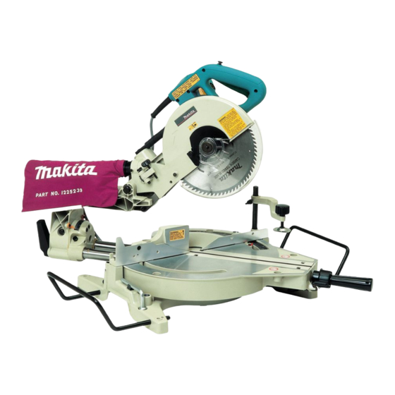
Makita LS1013 Instruction Manual
Slide compound saw equipped with electric blade brake 255 mm (10”)
Hide thumbs
Also See for LS1013:
- Instruction manual (120 pages) ,
- Parts breakdown (6 pages) ,
- Instruction manual (92 pages)
Table of Contents
Advertisement
Advertisement
Table of Contents

Related Manuals for Makita LS1013


Summary of Contents for Makita LS1013
- Page 1 Slide Compound Saw Equipped with Electric Blade Brake 255 mm (10”) MODEL LS1013 I N S T R U C T I O N WARNING: For your personal safety, READ and UNDERSTAND before using. SAVE THESE INSTRUCTIONS FOR FUTURE REFERENCE.
-
Page 2: Specifications
SPECIFICATIONS Blade diameter : ... 255 mm (10”) Hole diameter : ... 15.88 mm (5/8”) Max. Cutting capacities (H x W) Miter angle 0° 45° (left and right) 52° (right) No load speed (RPM) : ... 3,700/min. Dimensions (L x W x H) : ... 760 mm x 520 mm x 625 mm (29-7/8” x 20-1/2” x 24-5/8”) Net weight : ... - Page 3 6. KEEP CHILDREN AWAY. should be kept safe distance from work area. 7. MAKE WORKSHOP KID PROOF with pad- locks, master switches, or by removing starter keys. 8. DON’T FORCE TOOL. It will do the job bet- ter and safer at the rate for which it was designed.
-
Page 4: Use Proper Extension Cord
Not More Than ADDITIONAL SAFETY RULES DO NOT let comfort or familiarity with product (gained from repeated use) replace strict adherence to slide compound saw safety rules. If you use this tool unsafely or incorrectly, you can suffer serious personal injury. - Page 5 12. Check the blade carefully for cracks or damage before operation. cracked or damaged blade immediately. Gum and wood pitch hardened on blades slows saw and increases potential for kickback. Keep blade clean by first remov- ing it from tool, then cleaning it with gum and pitch remover, hot water or kerosene.
- Page 6 32. Some material contains chemicals which may be toxic. Take caution to prevent dust SAVE THESE INSTRUCTIONS WARNING: MISUSE or failure to follow the safety rules stated in this instruction manual may cause serious personal injury. inhalation and skin contact. Follow mate- rial supplier safety data.
-
Page 7: Blade Guard
INSTALLATION 001564 1. Stopper pin 001531 1. Bolt FUNCTIONAL DESCRIPTION 001535 1. Blade guard Bench mounting When the tool is shipped, the handle is locked in the lowered position by the stopper pin. Release the stopper pin by lower- ing the handle slightly and pulling the stopper pin. This tool should be bolted with four bolts to a level and stable surface using the bolt holes provided in the tool’s base. -
Page 8: Positioning Kerf Board
Do not remove spring holding blade guard. If guard becomes discolored through age or UV light exposure, con- tact a Makita service center for a new guard. DO NOT DEFEAT OR REMOVE GUARD. Positioning kerf board This tool is provided with the kerf boards in the turn base to minimize tearing on the exit side of a cut. -
Page 9: Maintaining Maximum Cutting Capacity
001538 1. Saw blade 2. Blade teeth 3. Kerf board 4. Left bevel cut 5. Straight cut 6. Right bevel cut 001539 1. Adjusting bolt 2. Turn base 001540 1. Top surface ot turn base 2. Periphery of blade 3. Guide fence First, unplug the tool. -
Page 10: Stopper Arm
001562 1. Adjusting screw 2. Stopper arm 001541 1. Lock lever 2. Grip 3. Pointer 4. Miter scale 001542 1. Lever Stopper arm The lower limit position of the blade can be easily adjusted with the stopper arm. To adjust it, move the stopper arm in the direction of the arrow as shown in the figure. -
Page 11: Switch Action
NEVER use the tool if it runs when you simply pull the switch trigger without pressing the lock-off button. Return tool to a Makita service center for proper repairs BEFORE further usage. •... -
Page 12: Installing/Removing Saw Blade
Always be sure that the tool is switched off and unplugged before installing or removing the blade. • Use only the Makita socket wrench provided to install or remove the blade. Failure to do so may result in overtightening or insufficient tightening of the hex bolt. - Page 13 001532 1. Center cover 2. Hex bolt 3. Socket wrench 4. Blade guard 001533 1. Blade case 2. Arrow 3. Shaft lock 4. Hex bolt 5. Socket wrench 001786 1. Hex bolt 2. Outer flange 3. Saw blade 4. Inner flange 5.
-
Page 14: Securing Workpiece
NOTE: If you connect a Makita vacuum cleaner to your saw, more efficient and cleaner operations can be performed. Securing workpiece WARNING: •... - Page 15 001549 1. Support 2. Turn base 001545 1. Sub-fence 001546 1. Sub-fence 001547 1. Sub-fence R 2. Screws CAUTION: • When cutting long workpieces, use supports that are as high as the top surface level of the turn base. Do not rely solely on the vertical vise and/or horizontal vise to secure the workpiece.
- Page 16 001548 1. Vise arm 2. Vise rod 3. Screw 4. Clamp screw 5. Guide fence 001550 1. Vise plate 2. Vise nut 3. Vise knob Vertical vise The vertical vise can be installed in two positions on either the left or right side of the guide fence or the base. Insert the vise rod into the hole in the guide fence or the base and tighten the screw to secure the vise rod.
-
Page 17: Operation
001544 1. Holder OPERATION 001552 1. Knob Holders The holders can be installed on either side as a convenient means of holding workpieces horizontally. Slip the holder rods into the holes in the base and adjust their length accord- ing to the workpiece to be held. Then tighten the holders securely with the screws. - Page 18 001553 1. Knob and WAIT UNTIL THE BLADE HAS COME TO A COM- PLETE STOP before returning the blade to its fully ele- vated position. CAUTION: • Firmly tighten the knob clockwise so that the carriage will not move during operation. Insufficient tightening may cause unexpected kickback of the blade.
- Page 19 4. Bevel cut 001554 Loosen the lever and tilt the saw blade to set the bevel angle (Refer to the previously covered “Adjusting the bevel angle”). Be sure to retighten the lever firmly to secure the selected bevel angle safely. Secure the work- piece with a vise.
- Page 20 001555 52∞ 45∞ 45∞ 38∞ 45∞ 45∞ 1. 52/38° type crown molding 2. 45° type crown molding 3. 45° type cove molding 001556 (1) (2) (3) (4) Fig.A 1. Inside corner 2. Outside corner 001557 1. Inside corner 2. Outside corner 6.
- Page 21 Example: In the case of cutting 52/38° type crown molding for position (1) in Fig. A: • Tilt and secure bevel angle setting to 33.9° LEFT. • Adjust and secure miter angle setting to 31.6° RIGHT. • Lay crown molding with its broad back (hidden) surface down on the turn base with its CEILING CONTACT EDGE against the guide fence on the saw.
- Page 22 000031 Ceiling 52˚ 38˚ Wall to Crown Molding Angle: 52/38 degrees Wall Angle Bevel Angle Miter Angle (deg.) (deg.) (deg.) 43.0 46.8 42.8 46.3 42.5 45.7 42.2 45.1 41.9 44.6 41.7 44.0 41.4 43.5 41.1 42.9 40.8 42.4 40.5 41.9 40.2 41.3 39.9...
- Page 23 000032 Ceiling 45˚ 45˚ Wall to Crown Molding Angle: 45 degrees Wall Angle Bevel Angle Miter Angle (deg.) (deg.) (deg.) 37.8 50.8 37.5 50.2 37.3 49.6 37.1 49.1 36.8 48.5 36.6 48.0 36.4 47.4 36.1 46.9 35.9 46.4 35.6 45.8 35.4 45.3 35.1...
- Page 24 001558 Fig. B 1. Crown molding stopper L 2. Crown molding stopper R 3. Turn base 001559 Fig. C 1. Crown molding stopper L 2. Crown molding stopper R 3. Turn base 001560 1. Guide fence 2. Crown molding 3. Crown molding stopper 4.
-
Page 25: Carrying Tool
001561 1. Guide fence 2. Vise 3. Spacer block 4. Aluminum extrusion 5. Spacer block 001563 1. Cut grooves with blade 001564 1. Stopper pin 7. Cutting aluminum extrusion When securing aluminum extrusions, use spacer blocks or pieces of scrap as shown in the figure to prevent deformation of the aluminum. -
Page 26: Adjusting Cutting Angle
001565 MAINTENANCE 001566 1. Guide fence 2. Hex bolts 001567 1. Guide fence 2. Triangular rule Carry the tool by holding both sides of the tool base as shown in the figure. If you remove the holders, dust bag, etc., you can carry the tool more easily. - Page 27 001568 1. Screw 2. Miter scale 3. Pointer 001569 1. Arm 2. Lever 3. Hex bolt 001570 1. Hex bolt 001571 1. Triangular rule 2. Saw blade 3. Top surface of turn base Make sure that the pointer points to 0° on the miter scale.
-
Page 28: Replacing Carbon Brushes
10 minutes. Then check the tool while running and electric brake operation when releasing the switch trigger. If electric brake is not working well, ask your local Makita service center for repair. -
Page 29: After Use
When storing the tool, pull the carriage toward you fully so that the slide pole is thoroughly inserted into the turn base. To maintain product SAFETY and RELIABILITY, repairs, any other maintenance or adjustment should be performed by Makita Authorized or Factory Service Centers, always using Makita replacement parts. - Page 30 CAUTION: • These accessories or attachments are recommended for use with your Makita tool specified in this manual. The use of any other accessories or attachments might present a risk of injury to persons. Only use accessory or attachment for its stated purpose.
- Page 31 Memo...
- Page 32 Memo...
- Page 33 First-Class Postage Required Post Office will not deliver without proper postage. Makita U.S.A., Inc. 14930 Northam Street La Mirada, CA 90638-5753 Fold...
- Page 34 Paste 3. How did you learn about this product: Magazine From Dealer Newspaper Store Display Catalog 4. Most favored points are: Design Features Size Price Makita Brand MODEL NO. YEAR SERIAL NO. PHONE 20-29 30-39 40-49 Paste Paste Radio Exhibition...
-
Page 35: Factory Service Centers
Date Purchased When you need service: Send complete tool (prepaid) to one Dealer’s Name & Address of the Makita Factory Service Centers listed, or to an Authorized Makita Service Center. Be sure to attach a letter to the outside of Model No. -
Page 36: Warranty Policy
MAKITA LIMITED ONE YEAR WARRANTY Warranty Policy Every Makita tool is thoroughly inspected and tested before leaving the factory. It is warranted to be free of defects from workmanship and materials for the period of ONE YEAR from the date of original purchase.