
Related Manuals for Miller Econotig


Summary of Contents for Miller Econotig
- Page 1 Visit our website at www.MillerWelds.com Econotig OM-303 155 795T May 2005 Processes Gas Tungsten Arc (TIG) Welding Shielded Metal Arc (Stick) Welding Description Arc Welding Power Source...
- Page 2 From Miller to You Thank you and congratulations on choosing Miller. Now you can get the job done and get it done right. We know you don’t have time to do it any other way. That’s why when Niels Miller first started building arc welders in 1929, he made sure his products offered long-lasting value and superior quality.
-
Page 3: Table Of Contents
TABLE OF CONTENTS SECTION 1 − SAFETY PRECAUTIONS - READ BEFORE USING 1-1. Symbol Usage ............... . 1-2. - Page 4 Notes...
-
Page 5: Section 1 − Safety Precautions - Read Before Using
SECTION 1 − SAFETY PRECAUTIONS - READ BEFORE USING Y Warning: Protect yourself and others from injury — read and follow these precautions. 1-1. Symbol Usage Means Warning! Watch Out! There are possible hazards with this procedure! The possible hazards are shown in the adjoining symbols. - Page 6 ARC RAYS can burn eyes and skin. Arc rays from the welding process produce intense visible and invisible (ultraviolet and infrared) rays that can burn eyes and skin. Sparks fly off from the weld. D Wear an approved welding helmet fitted with a proper shade of fil- ter lenses to protect your face and eyes when welding or watching (see ANSI Z49.1 and Z87.1 listed in Safety Standards).
-
Page 7: Additional Symbols For Installation, Operation, And Maintenance
1-3. Additional Symbols For Installation, Operation, And Maintenance FIRE OR EXPLOSION hazard. D Do not install or place unit on, over, or near combustible surfaces. D Do not install unit near flammables. D Do not overload building wiring − be sure power supply system is properly sized, rated, and protected to handle this unit. -
Page 8: Principal Safety Standards
1-5. Principal Safety Standards Safety in Welding, Cutting, and Allied Processes, ANSI Standard Z49.1, from Global Engineering Documents (phone: 1-877-413-5184, website: www.global.ihs.com). Recommended Safe Practices for the Preparation for Welding and Cut- ting of Containers and Piping, American Welding Society Standard F4.1 from Global... -
Page 9: Section 2 − Consignes De Sécurité − À Lire Avant Utilisation
SECTION 2 − CONSIGNES DE SÉCURITÉ − À LIRE AVANT 2-1. Signification des symboles Signifie « Mise en garde. Faire preuve de vigilance. » Cette procédure présente des risques identifiés par les symboles adjacents aux directives. Y Identifie un message de sécurité particulier. Signifie «... - Page 10 LES RAYONS DE L’ARC peuvent cau- ser des brûlures oculaires et cuta- nées. Le rayonnement de l’arc génère des rayons visibles et invisibles intenses (ultraviolets et infrarouges) suscep- tibles de causer des brûlures oculaires et cutanées. Des étincelles sont projetées pendant le soudage. D Porter un masque de soudage muni d’un filtre de la nuance adéquate pour se protéger le visage et les yeux pendant le soudage ou pour re- garder (voir les normes de sécurité...
-
Page 11: Autres Symboles Relatifs À L'installation, Au Fonctionnement Et À L'entretien De L'appareil
2-3. Autres symboles relatifs à l’installation, au fonctionnement et à l’entretien de l’appareil. Risque D’INCENDIE OU D’EXPLO- SION D Ne pas placer l’appareil sur une surface inflam- mable, ni au−dessus ou à proximité d’elle. D Ne pas installer l’appareil à proximité de produits inflammables. D Ne pas surcharger l’installation électrique −... -
Page 12: Principales Normes De Sécurité
2-4. Principales normes de sécurité Safety in Welding, Cutting, and Allied Processes, norme ANSI Z49.1, de l’American Welding Society, 550 N.W. LeJeune Rd, Miami FL 33126 (téléphone : (305) 443−9353, site Web : www.aws.org). Recommended Safe Practices for the Preparation for Welding and Cut- ting of Containers and Piping, norme American Welding Society AWS F4.1, de l’American Welding Society, 550 N.W. -
Page 13: Section 3 − Definitions
SECTION 3 − DEFINITIONS 3-1. General Precautionary Label OM-303 Page 9... -
Page 14: Symbols And Definitions
3-2. Symbols And Definitions Tig Welding Output Electrode Positive Amperes Amperage Control/ Panel Rated No Load Voltage (Average) Rated Maximum 1max Supply Current Percent SECTION 4 − INTRODUCTION 4-1. Included with Your Unit OM-303 Page 10 Remote Foot/Hand Control Alternating Current Electrode Negative Work... -
Page 15: Specifications
4-2. Specifications A. 60 Hertz Models Rated Output at 20% Duty Welding Amperage Range Cycle AC High TIG: 150 A at 15 VDC (GTAW) 150 A at 15 VAC 50−165 Stick: 130 A at 25 VDC (SMAW) 150 A at 25 VAC 35−165 * () While idling. -
Page 16: Section 5 − Installation
SECTION 5 − INSTALLATION 5-1. Selecting a Location 18 in (460 mm) 5-2. Typical Stick Connections OM-303 Page 12 18 in (460 mm) 18 in (460 mm) Position unit so air can circulate. For information about sources of high-frequency see Section 9. For carts and caster kits see back of book or contact your distributor. -
Page 17: Typical Tig Connections
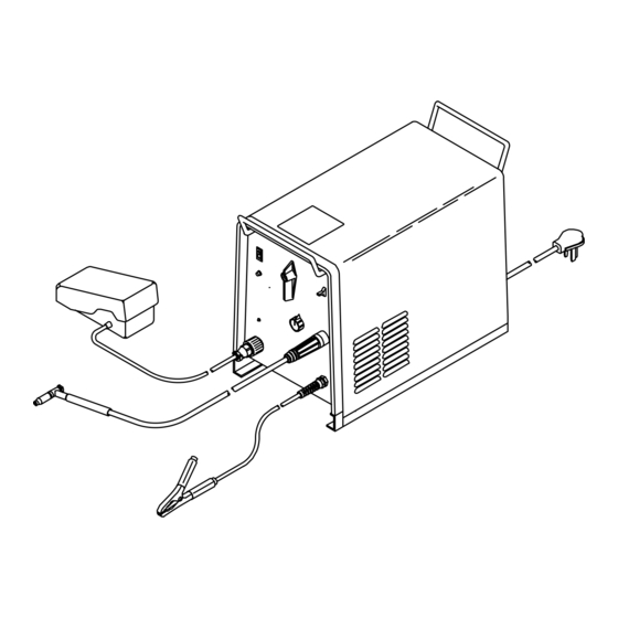
5-3. Typical TIG Connections Tools Needed: 5/8, 1-1/8 in Y Turn Off power before mak- ing connections. Remote Control Torch Connect to receptacles as shown. Work Clamp Cylinder Chain or secure cylinder to running gear, wall, or other stationary support. Cylinder Valve Open valve slightly so gas flow blows dirt from valve. -
Page 18: Electrical Service Guide
5-4. Electrical Service Guide For 230 V models with wall receptacle, 100% duty cycle used to calculate data below. 20% duty cycle used for all other models. Input Voltage Input Amperes At Rated Output Max Recommended Standard Fuse Rating In Amperes Normal Operating Min Input Conductor Size In AWG Max Recommended Input Conductor Length In Feet (Meters) -
Page 19: Section 6 − Operation
SECTION 6 − OPERATION 6-1. Controls Weld Process Switch Use switch to select weld process. In Stick position (down), weld output goes On and Off with Power switch. In GTAW (TIG) position (up), remote control device turns on and adjusts weld output of unit as limited by Amperage control. -
Page 20: Example Of Front Panel Amperage Control
6-2. Example of Front Panel Amperage Control Select weld process. Select range and polarity. 6-3. Example of Remote Amperage Control Select weld process. Connect remote control. OM-303 Page 16 Select percentage. Select range and polarity. GTAW Welding Amperage Range AC Low AC High 20-50 A 60-165 A... -
Page 21: Process And Material Thickness Guide Label
6-4. Process and Material Thickness Guide Label Guideline For Welding Process And Output For Material Material Thickness Material And 22 ga 20 ga 18 ga 16 ga 14 ga 12 ga 11 ga 10 ga 6 ga 2 ga − 0.033 in 0.036 in 0.048 in... -
Page 22: Section 7 − Maintenance And Troubleshooting
SECTION 7 − MAINTENANCE AND TROUBLESHOOTING 7-1. Routine Maintenance 3 Months Replace unreadable labels. Repair or replace cracked weld cable. Replace o-ring in Electrode/Gas Output receptacle if cracked. 6 Months Blow out or vacuum inside. 7-2. Troubleshooting Trouble No weld output; fan does not run. Place line disconnect switch in On position (see Section 5-5). -
Page 23: Section 8 − Electrical Diagrams
SECTION 8 − ELECTRICAL DIAGRAMS SB-154 141-C Figure 8-1. Circuit Diagram OM-303 Page 19... -
Page 24: Section 9 − High Frequency
SECTION 9 − HIGH FREQUENCY 9-1. Welding Processes Requiring High Frequency 9-2. Incorrect Installation Sources of Direct High-Frequency Radiation High-Frequency Source (welding power source with built-in HF or separate HF unit) Weld Cables Torch Work Clamp Workpiece Work Table OM-303 Page 20 Work Weld Zone 11, 12... -
Page 25: Correct Installation
9-3. Correct Installation 50 ft (15 m) Ground all metal ob- jects and all wiring in welding zone using #12 AWG wire. Nonmetal Building High-Frequency Source (welding power source with built-in HF or separate HF unit) Ground metal machine case, work output terminal, line disconnect device, input supply, and worktable. -
Page 26: Main Assembly Parts List
SECTION 10 − PARTS LIST Hardware is common and not available unless listed. ST-801 399-D Figure 10-1. Main Assembly OM−303 Page 22... - Page 27 Item Dia. Part Mkgs....154 335 ....203 990 .
- Page 28 Item Dia. Part Mkgs... . 157 958 ....155 422 ..
- Page 29 Notes...
- Page 30 Notes...
- Page 31 Warranty Questions? Call LIMITED WARRANTY − Subject to the terms and conditions below, Miller Electric Mfg. Co., Appleton, Wisconsin, warrants to 1-800-4-A-MILLER its original retail purchaser that new Miller equipment sold after for your local the effective date of this limited warranty is free of defects in material and workmanship at the time it is shipped by Miller.
-
Page 32: Owner's Record
Owner’s Record Please complete and retain with your personal records. Model Name Purchase Date (Date which equipment was delivered to original customer.) Distributor Address City State For Service Contact a DISTRIBUTOR or SERVICE AGENCY near you. Always provide Model Name and Serial/Style Number. Contact your Distributor for: Contact the Delivering Carrier to: PRINTED IN USA...
Need help?
Do you have a question about the Econotig and is the answer not in the manual?
Questions and answers