Table of Contents
Advertisement
Quick Links
Scan this tag with your mobile device
to learn more about this product.
Individual carrier rates may apply.
Start by downloading the free
mobile app at http://gettag.mobi
For product information,
Owner's Manual translations,
and more, visit
www.MillerWelds.com/ams
Axcess E Welding
Power Sources
OM-249474K
Processes
Description
Automatic Welding Interface And
Arc Welding Power Source
R
CE
File: Advanced Manufacturing Systems
2016−07
MIG (GMAW) Welding
Pulsed MIG (GMAW-P)
Flux Cored (FCAW) Welding
Automatic Welding
Advertisement
Table of Contents
Troubleshooting

Related Manuals for Miller AXCESS E 450 CE


Summary of Contents for Miller AXCESS E 450 CE
-
Page 1: Power Sources
OM-249474K 2016−07 Processes MIG (GMAW) Welding Pulsed MIG (GMAW-P) Flux Cored (FCAW) Welding Automatic Welding Description Automatic Welding Interface And Arc Welding Power Source Scan this tag with your mobile device to learn more about this product. Individual carrier rates may apply. Start by downloading the free mobile app at http://gettag.mobi Axcess E Welding... - Page 2 We know you don’t have time to do it any other way. That’s why when Niels Miller first started building arc welders in 1929, he made sure his products offered long-lasting value and superior quality.
-
Page 3: Table Of Contents
TABLE OF CONTENTS SECTION 1 − SAFETY PRECAUTIONS - READ BEFORE USING ....... . . 1-1. - Page 4 TABLE OF CONTENTS 8-5. Arranging Welding Cables To Reduce Welding Circuit Inductance ......8-6.
-
Page 5: Declaration Of Conformity
DECLARATION OF CONFORMITY for European Community (CE marked) products. MILLER Electric Mfg. Co., 1635 Spencer Street, Appleton, WI 54914 U.S.A. declares that the product(s) identified in this declaration conform to the essential requirements and provisions of the stated Council Directive(s) and Standard(s). - Page 6 EMF DATA SHEET FOR ARC WELDING POWER SOURCE Product/Apparatus Identification Product Stock Number AXCESS E 450 W/CE 907439002 AXCESS E 300 W/CE 907440002 AUTO-AXCESS E 300 ANALOG W/CE 907442002 AUTO-AXCESS E 450 ANALOG W/CE 907443002 AUTO-AXCESS E 450 DIGITAL W/CE 907496002 AUTO-AXCESS E 300 DIGITAL W/CE 907497002...
-
Page 7: Section 1 − Safety Precautions - Read Before Using
SECTION 1 − SAFETY PRECAUTIONS - READ BEFORE USING som 2015−09 Protect yourself and others from injury — read, follow, and save these important safety precautions and operating instructions. 1-1. Symbol Usage DANGER! − Indicates a hazardous situation which, if Indicates special instructions. - Page 8 D Remove stick electrode from holder or cut off welding wire at FUMES AND GASES can be hazardous. contact tip when not in use. D Wear body protection made from durable, flame−resistant material Welding produces fumes and gases. Breathing (leather, heavy cotton, wool). Body protection includes oil-free these fumes and gases can be hazardous to your clothing such as leather gloves, heavy shirt, cuffless trousers, high health.
-
Page 9: Additional Symbols For Installation, Operation, And Maintenance
1-3. Additional Symbols For Installation, Operation, And Maintenance FIRE OR EXPLOSION hazard. MOVING PARTS can injure. D Do not install or place unit on, over, or near D Keep away from moving parts such as fans. combustible surfaces. D Keep all doors, panels, covers, and guards D Do not install unit near flammables. -
Page 10: California Proposition 65 Warnings
1-4. California Proposition 65 Warnings Welding or cutting equipment produces fumes or gases This product contains chemicals, including lead, known to which contain chemicals known to the State of California to the state of California to cause cancer, birth defects, or other cause birth defects and, in some cases, cancer. -
Page 11: Section 2 − Consignes De Sécurité − Lire Avant Utilisation
SECTION 2 − CONSIGNES DE SÉCURITÉ − LIRE AVANT UTILISATION fre_som_2015−09 Pour écarter les risques de blessure pour vous−même et pour autrui — lire, appliquer et ranger en lieu sûr ces consignes relatives aux précautions de sécurité et au mode opératoire. 2-1. - Page 12 chauffement ou un incendie. Avant de commencer le soudage, vérifier LES PIÈCES CHAUDES peuvent et s’assurer que l’endroit ne présente pas de danger. provoquer des brûlures. D Déplacer toutes les substances inflammables à une distance de D Ne pas toucher à mains nues les parties chaudes. 10,7 m de l’arc de soudage.
-
Page 13: Dangers Supplémentaires En Relation Avec L'installation, Le Fonctionnement Et La Maintenance
D Tenir les bouteilles éloignées des circuits de soudage ou autres LE BRUIT peut endommager l’ouïe. circuits électriques. D Ne jamais placer une torche de soudage sur une bouteille à gaz. Le bruit des processus et des équipements peut affecter l’ouïe. D Une électrode de soudage ne doit jamais entrer en contact avec D Porter des protections approuvées pour les une bouteille. -
Page 14: Proposition Californienne 65 Avertissements
RAYONNEMENT HAUTE LE SOUDAGE À L’ARC risque de FRÉQUENCE (H.F.) risque provoquer des interférences. provoquer des interférences. D L’énergie électromagnétique risque D Le rayonnement haute fréquence (H.F.) peut provoquer des interférences pour l’équipement provoquer des interférences avec les équi- électronique sensible tel que les ordinateurs et l’équipement commandé... -
Page 15: Section 3 − Definitions
SECTION 3 − DEFINITIONS 3-1. Additional Safety Symbols and Definitions Some symbols are found only on CE products. Warning! Watch Out! There are possible hazards as shown by the symbols. Safe1 2012−05 Wear dry insulating gloves. Do not touch electrode with bare hand. Do not wear wet or damaged gloves. Safe2 2012−05 Protect yourself from electric shock by insulating yourself from work and ground. - Page 16 Do not remove or paint over (cover) the label. Safe20 2012−05 When power is applied failed parts can explode or cause other parts to explode. Safe26 2012−05 Flying pieces of parts can cause injury. Always wear a face shield when servicing unit. Safe27 2012−05 Always wear long sleeves and button your collar when servicing unit.
-
Page 17: Miscellaneous Symbols And Definitions
Hazardous voltage remains on input capacitors after power is turned off. Do not touch fully charged capacitors. Always wait 5 minutes after power is turned off before working on unit, OR check input capacitor voltage, and be sure it is near 0 before touching any parts. >5min Safe43 2012−05 = <... - Page 18 Notes OM-249474 Page 12...
-
Page 19: Section 4 − Specifications For Axcess E 300
SECTION 4 − SPECIFICATIONS FOR AXCESS E 300 4-1. Serial Number And Rating Label Location The serial number and rating information for this product is located on the front. Use rating label to determine input power requirements and/or rated output. For future reference, write serial number in space provided on back cover of this manual. 4-2. -
Page 20: Duty Cycle And Overheating
4-4. Duty Cycle And Overheating Duty Cycle is percentage of 10 minutes that unit can weld at rated load without overheating. If unit overheats, thermostat(s) opens, output stops, and cooling fan runs. Wait fifteen minutes for unit to cool. Reduce amperage or duty cycle before welding. -
Page 21: Electrical Service Guide
4-6. Electrical Service Guide Elec Serv 2014−01 Failure to follow these electrical service guide recommendations could create an electric shock or fire hazard. These recommenda- tions are for a dedicated circuit sized for the rated output and duty cycle of the welding power source. In dedicated circuit installations, the National Electrical Code (NEC) allows the receptacle or conductor rating to be less than the rating of the circuit protection device. -
Page 22: Environmental Specifications
4-7. Environmental Specifications A. IP Rating IP Rating IP21S This equipment is designed for indoor use and is not intended to be used or stored outside. IP21S 2014−06 B. Information On Electromagnetic Compatibility (EMC) For Axcess E 300 This Class A equipment is not intended for use in residential locations where the electrical power is provided by the public low− voltage supply system. -
Page 23: Section 5 − Specifications For Axcess E 450
SECTION 5 − SPECIFICATIONS FOR AXCESS E 450 5-1. Serial Number And Rating Label Location The serial number and rating information for this product is located on the front. Use rating label to determine input power requirements and/or rated output. For future reference, write serial number in space provided on back cover of this manual. 5-2. -
Page 24: Duty Cycle And Overheating
5-4. Duty Cycle And Overheating Duty Cycle is percentage of 10 minutes that unit can weld at rated load without overheating. If unit overheats, thermostat(s) opens, output stops, and cooling fan runs. Wait fifteen minutes for unit to cool. Reduce amperage or duty cycle before welding. -
Page 25: Electrical Service Guide
5-6. Electrical Service Guide Elec Serv 2014−01 Failure to follow these electrical service guide recommendations could create an electric shock or fire hazard. These recommenda- tions are for a dedicated branch circuit sized for the rated output and duty cycle of the welding power source. In dedicated circuit installations, the National Electrical Code (NEC) allows the receptacle or conductor rating to be less than the rating of the circuit protection device. -
Page 26: Environmental Specifications
5-7. Environmental Specifications A. IP Rating IP Rating IP21S This equipment is designed for indoor use and is not intended to be used or stored outside. IP21S 2014−06 B. Information On Electromagnetic Compatibility (EMC) For Axcess E 450 This Class A equipment is not intended for use in residential locations where the electrical power is provided by the public low− voltage supply system. -
Page 27: Section 6 − License Agreement
SECTION 6 − LICENSE AGREEMENT You have acquired a device (Axcess E) which includes software licensed by Miller Electric Mfg. Co. from one or more software licensors (EUROTECH, Inc. software suppliers). Such software products, as well as associated media, printed materials, and “online” or electronic documentation for such software are protected by international intellectual property laws and treaties. -
Page 28: Connection Diagram
7-2. Connection Diagram Welding Power Source Wire Feeder Gas Cylinder Gas Hose Network Feeder Cable Negative (−) Weld Cable Workpiece Voltage Sensing Lead Recommended for Accu-pulse and required for RMD. Positive (+) voltage sensing lead is contained in the motor cable. -
Page 29: Upper Rear Panel Receptacles
7-4. Upper Rear Panel Receptacles Ethernet Receptacle Port A Ethernet Receptacle Port B Port A and Port B are identified by the IP address from the network server. Ethernet receptacles provide connections for either a network cable or a laptop PC or both. Optional MWCI Receptacle Optional WFS (Wire Feed Sensor) Optional GFS (Gas Flow Sensor) -
Page 30: Network Wire Feeder Receptacle Functions
7-6. Network Wire Feeder Receptacle Functions Pin* Pin Information Not used. Shield. Volt sense. Can low. Can high. +24 volts DC common. + 24 volts DC Motor voltage +40 volts DC common Motor voltage +40 volts DC Ref. 245 741-C *The remaining pins are not used. -
Page 31: Removing Cover And Measuring Input Capacitor Voltage
7-8. Removing Cover and Measuring Input Capacitor Voltage Turn Off welding power source, and disconnect in- put power. Significant DC voltage can Tools Needed: remain on capacitors after unit is Off. Always check the voltage as shown to be sure 5/16 in. -
Page 32: Connecting 3-Phase Input Power
7-9. Connecting 3-Phase Input Power = GND/PE Earth Ground Route input conductors to filter board. Route ground conductor through tubing and current transducer to ground terminal. Tools Needed: 5/16 in. Input5 2016-06 − 251 184-C / Ref.803 855-B / Ref. 803 766-C / 219 842-A OM-249474 Page 26... - Page 33 7-9. Connecting 3-Phase Input Power (Continued) Section 4-6 or 5-6. Conductors must comply L1, L2, and L3 to welding power source line Turn Off welding power source, and with national, state, and local electrical terminals. check voltage on input capacitors codes.
-
Page 34: Section 8 − Recommended Setup Procedures
( ) = mm for metric use ***For distances longer than those shown in this guide, call a factory applications rep. at 920-735-4505 (Miller) or 1-800-332-3281 (Hobart). Ref. S-0007-L 2015−02 In pulse welding applications using inverter power sources, peak currents can result in extreme voltage drops producing poor welding characteris- tics with undersized cables. -
Page 35: Connecting To Weld Terminals
8-3. Connecting To Weld Terminals Do not place anything between weld cable terminal and copper bar. Correct Installation Incorrect Installation Tools Needed: 3/4 in. (19 mm) 245 733-C / 803 778-A combined) maximum welding Remove supplied nut from weld output Turn off power before connecting to amperes. -
Page 36: Welding Circuit
8-4. Welding Circuit Minimizing the welding circuit loop can prevent extreme voltage drops that produce poor welding characteristics. Welding Power Source Electrode Cable Feeder Cable Work Cable Standard Welding Circuit Voltage Sensing Lead Wire Feeder Workpiece In pulse welding applications using inverter power sources,... -
Page 37: Arranging Welding Cables To Reduce Welding Circuit Inductance
8-5. Arranging Welding Cables To Reduce Welding Circuit Inductance Welding Power Source Electrode Cable Feeder Cable Work Cable Voltage Sensing Lead Wire Feeder Workpiece The arrangement of the cables has an effect that is significant to the welding properties. As an example, Accupulse welding process can produce high welding circuit inductance depending on cable length and arrangement. -
Page 38: Using Multiple Welding Power Sources
Welding on a single workpiece using multiple welding power sources can cause arc blow and arc impedance to develop or intensify. 8-6. Using Multiple Welding Power Sources Welding Power Source Electrode Cable Feeder Cable Work Cable Voltage Sensing Lead Wire Feeder Workpiece Each welding power source should have a separate work cable connection... -
Page 39: Voltage Sensing Lead And Work Cable Connections For Multiple Welding Arcs
8-7. Voltage Sensing Lead And Work Cable Connections For Multiple Welding Arcs A. Bad Setup Current Flow Path Ref. 245 748-C Welding Power Source Workpiece across the workpiece will not be measured correctly for the voltage feedback signal. Electrode Cable This arrangement is a bad setup due to Voltage feedback to the welding power Feeder Cable... - Page 40 B. Better Setup Current Flow Path Ref. 245 750-C Welding Power Source Wire Feeder the welding power sources. The most accurate voltage sensing may not be Electrode Cable Workpiece achieved due to voltage drops in the Feeder Cable workpiece. This require Work Cable This arrangement is a better setup for...
- Page 41 C. Best Setup Current Flow Path Ref. 245 751-C Welding Power Source Voltage Sensing Lead This arrangement is the best setup for proper voltage sensing at the workpiece. Electrode Cable Wire Feeder Voltage feedback to the welding power Feeder Cable sources will more accurate and result in Work Cable Workpiece...
-
Page 42: Points Of Mechanics In Mig Welding 30 Pts Mig − 2014-09
8-8. 30 Points Of Mechanics In MIG Welding 30 Pts MIG − 2014-09 Primary Power Check primary power connection at line disconnect switch or receptacle and/or cord plug. Check primary power connection at welding power source. Secondary Power Check secondary weld output connections at welding power source. Inspect condition and routing of positive weld cable to wire drive motor. -
Page 43: Arc Blow
8-9. Arc Blow Arc blow is the deflection of the welding arc from its normal path due to magnetic forces. This condition is usually encountered in direct current welding of magnetic materials, such as iron and nickel. Arc blow can happen in alternating current welding under certain conditions, but these cases are rare and the intensity of the arc blow is always less severe. -
Page 44: Basic Welding Troubleshooting
8-10. Basic Welding Troubleshooting Listed below are some problems, causes and remedies related to welding operations; however, this list does not contain every possible condition that could be encountered in welding. Trouble Probable Cause Remedy No weld output; unit completely Line disconnect switch in Off position. - Page 45 Trouble Probable Cause Remedy Porosity in weld. Dirty base metal, heavy oxides, mill scale, oil, etc. Clean base metal by brushing, grinding or use chemical cleansing before welding. Regulator/flowmeter faulty. Adjust or replace regulator/flowmeter. Gas cylinder valve closed. Open gas cylinder valve. Gas regulator diaphragm defective.
- Page 46 Trouble Probable Cause Remedy Wandering, hunting or erratic arc. Restriction in unspooler or drum adapter. Replace unspooler or repair restriction. Dirty or worn gun liner or inlet cable. Remove gun liner or inlet cable and clean or replace. Sharp bends or kinks in gun cable or liner. Straighten gun cable and/or replace liner.
- Page 47 Trouble Probable Cause Remedy Shutdown at arc initiation using power No voltage feedback signal. Broken or disconnected voltage feedback lead, no source and feeder or interface. open circuit voltage, check power source. No current feedback signal. Poor parameters, open in weld circuit, faulty hall device, check power source.
-
Page 48: Section 9 − Operation
SECTION 9 − OPERATION 9-1. Operational Terms The following is a list of terms and their definitions as they apply to this interface unit: General Terms: Arc Adjust Term used to represent arc length adjustments in pulse programs. Increasing Arc Adjust increases the actual arc length. -
Page 49: Pulse Welding Terms
General Terms: TH (Trigger Hold) Trigger Hold allows the operator to feed wire without continuously pressing the gun trigger. In trigger hold mode, momentarily press gun trigger, and wire will feed until gun trigger is momentarily pressed again. Time Indicates time values being set for timed functions (e.g. Preflow, Postflow which are only available in the Arc On and Analog input or the Arc On and No Analog input modes). -
Page 50: Front Panel Switches
9-3. Front Panel Switches Power Switch Turns unit On or Off. Pilot Light Light indicates status of welding power source, on when unit is on and off when unit is off. Ref. 245 746-B OM-249474 Page 44... -
Page 51: Section 10 − Maintenance
SECTION 10 − MAINTENANCE 10-1. Routine Maintenance Disconnect power Maintain more often before maintaining. during severe conditions. n = Check Z = Change ~ = Clean l = Replace Reference * To be done by Factory Authorized Service Agent Every l Unreadable Labels ~ Weld Terminals l Damaged Gas Hose... - Page 52 Notes OM-249474 Page 46...
-
Page 53: Section 11 − Troubleshooting
SECTION 11 − TROUBLESHOOTING 11-1. Troubleshooting Trouble Remedy No weld output; completely inoperative Place line disconnect in On position (see Section 7-9). Check and replace line fuse(s), if necessary, or reset circuit breaker (see Section 7-9). Check for proper input power connections (see Section 7-9). No weld output;... -
Page 54: Check Web Message Display
11-2. Check Web Message Display When an existing Axcess power source is upgraded to an Axcess E, the first time the unit is powered up the message CHCK WEB will appear on the display (see Figure 11-1). CHCK Process Setup Adjust Feeder Setup Figure 11-1. - Page 55 Certain information must be entered on the web pages for the unit to function properly. The user will be prompted for power source serial number, model and type (Semi-Auto, AROI, AUTO, etc.) as shown in Figure 11-2. Figure 11-2. Web Site For Axcess E Information OM-249474 Page 49...
-
Page 56: Software Error Message Display
11-3. Software Error Message Display During the initial power up sequence, the ARM checks the UIM, WFCM and RIO for software numbers or revisions and compares them to what is stored to see if they are compatible. If these software versions are not compatible, the ERR S W will appear on the display (see Figure 11-3). -
Page 57: E Module Board Stack Diagnostic Leds
11-4. E Module Board Stack Diagnostic LEDs D10 D11 D7 D103 D101 D108 LED2 LED1 250 237-A / Ref. 245 768-C E Module Board Stack Refer to Section 11-5 for information on Reinstall cover after checking diagnostic diagnostic LEDs. LEDs. Diagnostic LEDs are visible inside unit, lo- cated on the E Module Board Stack. -
Page 58: Diagnostic Leds On E Module Board Stack
11-5. Diagnostic LEDs On E Module Board Stack A. DeviceNet Communication LEDs D7, D10, D11, D19, and D21 are off until communication is established. Once communication is established D7, D10, D11, and D19 flash on and off, and D21 turns on steady. If any of these LEDs are off, there is a problem. Contact the nearest factory Authorized Service Agent. Function Status Diagnosis... - Page 59 C. General Purpose LEDs Gnd Cnt − Indicates ground error. Contact nearest factory Authorized Service Agent. Indicates no error OVR CNT − Indicates an error. Contact nearest factory Authorized Service Agent. Indicates no error OVR PWR − Indicates unit is operating at max input current. Contact nearest factory Authorized Service Agent.
-
Page 60: Section 12 − Web Pages Site Tree
SECTION 12 − WEB PAGES SITE TREE The Axcess E machine IP address is required to open the web pages. If necessary, have the IT administrator provide this address to allow opening the web pages. Port A on the power source is factory set to 169.254.0.2 as a static IP address. Connect a PC to Port A and enter 169.254.0.2 in the web browser to access the web pages. - Page 61 Home Page Diagnostics Software System Settings Weld Ethernet Errors Communications More Time Settings Settings Axcess Upgrade Welder Options Information Subselect and Subselect and type additional type additional text here text here Machine Short Term Lifetime Weld Data Report OM-249474 Page 55...
- Page 62 ........Figure 13-3. Circuit Diagram For Axcess E 450 CE (1 Of 2) .
-
Page 63: Section 13 − Electrical Diagrams
SECTION 13 − ELECTRICAL DIAGRAMS 263 464-C (Part 1 Of 2) Figure 13-1. Circuit Diagram For Axcess E 300 CE (1 Of 2) OM-249474 Page 57... - Page 64 Figure 13-2. Circuit Diagram For Axcess E 300 CE (2 Of 2) OM-249474 Page 58...
- Page 65 263 464-C (Part 2 Of 2) OM-249474 Page 59...
- Page 66 Figure 13-3. Circuit Diagram For Axcess E 450 CE (1 Of 2) OM-249474 Page 60...
- Page 67 263 483-C (Part 1 Of 2) OM-249474 Page 61...
- Page 68 Figure 13-4. Circuit Diagram For Axcess E 450 CE (2 Of 2) OM-249474 Page 62...
- Page 69 263 483-C (Part 2 Of 2) OM-249474 Page 63...
- Page 70 Figure 13-5. Circuit Diagram For Axcess E Module OM-249474 Page 64...
- Page 71 250 571-C OM-249474 Page 65...
-
Page 72: Section 14 − Parts List For Axcess E 300
SECTION 14 − PARTS LIST FOR AXCESS E 300 Hardware is common and not available unless listed. 3 − Fig 14-3 8 − Fig 14-5 6 − Fig 14-4 7 − Fig 14-2 24 − Fig 14-6 249 544-F Figure 14-1. Axcess E 300 Main Assembly OM-249474 Page 66... - Page 73 Item Dia. Part Mkgs. Description Quantity Figure 14-1. Axcess E 300 Main Assembly ....+210492 . . . Cover, Top ........... .
- Page 74 Hardware is common and not available unless listed. 20 21 802 955-C Figure 14-2. Windtunnel Assembly LH And RH Item Dia. Part Mkgs. Description Quantity Figure 14-2. Windtunnel Assembly LH And RH (Fig 14-1 Item 7) ....214597 .
- Page 75 Item Dia. Part Mkgs. Description Quantity Figure 14-2. Windtunnel Assembly LH And RH (Fig 14-1 Item 6) (Continued) ..... . 115092 .
- Page 76 Hardware is common and not available unless listed. 245 871-E Figure 14-3. E-module w/Ethernet And USB Assembly Item Dia. Part Mkgs. Description Quantity Figure 14-3. E-module w/Ethernet And USB Assembly (Fig 14-1 Item 3) ....244923 .
- Page 77 Hardware is common and not available unless listed. 245 798-A Figure 14-4. Top Tray Assembly Item Dia. Part Mkgs. Description Quantity Figure 14-4. Top Tray Assembly (Fig 14-1 Item 4 And Fig 14-1 Item 6) ..
- Page 78 Hardware is common and not available unless listed. 248 796-B Figure 14-5. Axcess E 300 Rear Panel Assembly Item Dia. Part Mkgs. Description Quantity Figure 14-5. Axcess E 300 Rear Panel Assembly (Fig 14-1 Item 8) ....+210478 .
- Page 79 Hardware is common and not available unless listed. 248 806-A Figure 14-6. Axcess E 300 Front Panel Assembly Item Dia. Part Mkgs. Description Quantity Figure 14-6. Axcess E 300 Front Panel Assembly (Fig 14-1 Item 23) ..
-
Page 80: Section 15 − Parts List For Axcess E 450
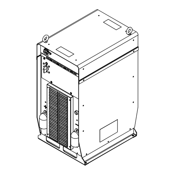
SECTION 15 − PARTS LIST FOR AXCESS E 450 Hardware is common and not available unless listed. 3 − Fig 15-3 7 − Fig 15-2 10 − Fig 15-5 6 − Fig 15-4 26 − Fig 15-6 249 528-F Figure 15-1. Axcess E 450 Main Assembly OM-249474 Page 74... - Page 81 Item Dia. Part Mkgs. Description Quantity Figure 15-1. Axcess E 450 Main Assembly ....+210492 . . . Cover, Top ........... .
- Page 82 Hardware is common and not available unless listed. 20 21 802 955-C Figure 15-2. Windtunnel Assembly LH And RH Item Dia. Part Mkgs. Description Quantity Figure 15-2. Windtunnel Assembly LH And RH (Fig 15-1 Item 7) ....214597 .
- Page 83 Item Dia. Part Mkgs. Description Quantity Figure 15-2. Windtunnel Assembly LH And RH (Fig 15-1 Item 7) (Continued) ..... . 115092 .
- Page 84 Hardware is common and not available unless listed. 245 871-E Figure 15-3. E-module w/Ethernet And USB Assembly Item Dia. Part Mkgs. Description Quantity Figure 15-3. E-module w/Ethernet And USB Assembly (Fig 15-1 Item 3) ....244923 .
- Page 85 Hardware is common and not available unless listed. 245 798-A Figure 15-4. Top Tray Assembly Item Dia. Part Mkgs. Description Quantity Figure 15-4. Top Tray Assembly (Fig 15-1 Item 6) ... . . 239598 .
- Page 86 Hardware is common and not available unless listed. 245 810-D Figure 15-5. Axcess E 450 Rear Panel Assembly Item Dia. Part Mkgs. Description Quantity Figure 15-5. Axcess E 450 Rear Panel Assembly (Fig 15-1 Item 10) ....+210474 .
- Page 87 Hardware is common and not available unless listed. 245 822-A Figure 15-6. Axcess E 450 Front Panel Assembly Item Dia. Part Mkgs. Description Quantity Figure 15-6. Axcess E 450 Front Panel Assembly (Fig 15-1 Item 25) ..
- Page 88 Notes MATERIAL THICKNESS REFERENCE CHART 24 Gauge (.025 in.) 22 Gauge (.031 in.) 20 Gauge (.037 in.) 18 Gauge (.050 in.) 16 Gauge (.063 in.) 14 Gauge (.078 in.) 1/8 in. (.125 in.) 3/16 in. (.188 in.) 1/4 in. (.25 in.) 5/16 in.
- Page 89 Effective January 1, 2016 (Equipment with a serial number preface of MG or newer) This limited warranty supersedes all previous Miller warranties and is exclusive with no other guarantees or warranties expressed or implied. Warranty Questions? LIMITED WARRANTY − Subject to the terms and conditions below, 6 Months —...
- Page 90 Contact the Delivering Carrier to: File a claim for loss or damage during shipment. For assistance in filing or settling claims, contact your distributor and/or equipment manufacturer’s Transportation Department. © ORIGINAL INSTRUCTIONS − PRINTED IN USA 2016 Miller Electric Mfg. Co. 2016−01...
Need help?
Do you have a question about the AXCESS E 450 CE and is the answer not in the manual?
Questions and answers