
Related Manuals for Miller Multimatic 215


Summary of Contents for Miller Multimatic 215
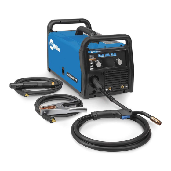
- Page 1 OM-272989A 2016−03 Processes Processes Multiprocess Welding Description Arc Welding Power Source Wire Feeder Multimatic 215 Visit our website at File: Multiprocess www.MillerWelds.com...
- Page 2 We know you don’t have time to do it any other way. That’s why when Niels Miller first started building arc welders in 1929, he made sure his products offered long-lasting value and superior quality.
-
Page 3: Table Of Contents
TABLE OF CONTENTS SECTION 1 − SAFETY PRECAUTIONS - READ BEFORE USING ....... . . 1-1. - Page 4 TABLE OF CONTENTS SECTION 6 − OPERATION ..............6-1.
-
Page 5: Section 1 − Safety Precautions - Read Before Using
SECTION 1 − SAFETY PRECAUTIONS - READ BEFORE USING som 2015−09 Protect yourself and others from injury — read, follow, and save these important safety precautions and operating instructions. 1-1. Symbol Usage DANGER! − Indicates a hazardous situation which, if Indicates special instructions. - Page 6 D Remove stick electrode from holder or cut off welding wire at FUMES AND GASES can be hazardous. contact tip when not in use. D Wear body protection made from durable, flame−resistant material Welding produces fumes and gases. Breathing (leather, heavy cotton, wool). Body protection includes oil-free these fumes and gases can be hazardous to your clothing such as leather gloves, heavy shirt, cuffless trousers, high health.
-
Page 7: Additional Symbols For Installation, Operation, And Maintenance
1-3. Additional Symbols For Installation, Operation, And Maintenance FIRE OR EXPLOSION hazard. MOVING PARTS can injure. D Do not install or place unit on, over, or near D Keep away from moving parts such as fans. combustible surfaces. D Keep all doors, panels, covers, and guards D Do not install unit near flammables. -
Page 8: California Proposition 65 Warnings
1-4. California Proposition 65 Warnings Welding or cutting equipment produces fumes or gases This product contains chemicals, including lead, known to which contain chemicals known to the State of California to the state of California to cause cancer, birth defects, or other cause birth defects and, in some cases, cancer. -
Page 9: Section 2 − Consignes De Sécurité − Lire Avant Utilisation
SECTION 2 − CONSIGNES DE SÉCURITÉ − LIRE AVANT UTILISATION fre_som_2015−09 Pour écarter les risques de blessure pour vous−même et pour autrui — lire, appliquer et ranger en lieu sûr ces consignes relatives aux précautions de sécurité et au mode opératoire. 2-1. - Page 10 chauffement ou un incendie. Avant de commencer le soudage, vérifier LES PIÈCES CHAUDES peuvent et s’assurer que l’endroit ne présente pas de danger. provoquer des brûlures. D Déplacer toutes les substances inflammables à une distance de D Ne pas toucher à mains nues les parties chaudes. 10,7 m de l’arc de soudage.
-
Page 11: Dangers Supplémentaires En Relation Avec L'installation, Le Fonctionnement Et La Maintenance
D Tenir les bouteilles éloignées des circuits de soudage ou autres LE BRUIT peut endommager l’ouïe. circuits électriques. D Ne jamais placer une torche de soudage sur une bouteille à gaz. Le bruit des processus et des équipements peut affecter l’ouïe. D Une électrode de soudage ne doit jamais entrer en contact avec D Porter des protections approuvées pour les une bouteille. -
Page 12: Proposition Californienne 65 Avertissements
RAYONNEMENT HAUTE LE SOUDAGE À L’ARC risque de FRÉQUENCE (H.F.) risque provoquer des interférences. provoquer des interférences. D L’énergie électromagnétique risque D Le rayonnement haute fréquence (H.F.) peut provoquer des interférences pour l’équipement provoquer des interférences avec les équi- électronique sensible tel que les ordinateurs et l’équipement commandé... -
Page 13: Section 3 − Definitions
SECTION 3 − DEFINITIONS 3-1. Additional Safety Symbols And Definitions Warning! Watch Out! There are possible hazards as shown by the symbols. Safe1 2012−05 Drive rolls can injure fingers. Welding wire and drive parts are at welding voltage during operation − keep hands and metal objects away. -
Page 14: Miscellaneous Symbols And Definitions
3-2. Miscellaneous Symbols And Definitions Gas Tungsten Arc Amperage Remote Welding (GTAW) Torch Voltage Shielded Metal Circuit Breaker Arc Welding (SMAW) Rated No Load Voltage (OCV) Positive Shielded Metal Arc (SMAW) Direct Current Electrode Holder (DC) Negative Alternating Gas Metal Arc Current (AC) Welding (GMAW) Duty Cycle... -
Page 15: Section 4 − Specifications
A complete Parts List is available at www.MillerWelds.com SECTION 4 − SPECIFICATIONS 4-1. Serial Number And Rating Label Location The serial number and rating information for this product is located on the back of unit. Use rating label to determine input power requirements and/or rated output. -
Page 16: Dimensions And Weight
A complete Parts List is available at www.MillerWelds.com 4-6. Dimensions And Weight 11 1/4 in. (286 mm) Weight 38 lb (17.2 kg) 12 1/2 in. (318 mm) 20 1/2 in. (521 mm) 275173A Notes Work like a Pro! Pros weld and cut safely. -
Page 17: Duty Cycle And Overheating For Mig (Gmaw)
A complete Parts List is available at www.MillerWelds.com 4-7. Duty Cycle And Overheating For MIG (GMAW) Duty Cycle is percentage of 10 minutes that unit can weld at rated load without overheating. If unit overheats, output stops. Wait fifteen minutes for unit to cool. Reduce amperage or duty cycle before starting to weld again. -
Page 18: Duty Cycle And Overheating For Tig (Gtaw)
A complete Parts List is available at www.MillerWelds.com 4-8. Duty Cycle And Overheating For TIG (GTAW) Duty Cycle is percentage of 10 minutes that unit can weld at rated load without overheating. If unit overheats, output stops. Wait fifteen minutes for unit to cool. Reduce amperage or duty cycle before starting to weld again. -
Page 19: Duty Cycle And Overheating For Stick (Smaw)
A complete Parts List is available at www.MillerWelds.com 4-9. Duty Cycle And Overheating For Stick (SMAW) Duty Cycle is percentage of 10 minutes that unit can weld at rated load without overheating. If unit overheats, output stops. Wait fifteen minutes for unit to cool. Reduce amperage or duty cycle before starting to weld again. -
Page 20: Section 5 − Installation
A complete Parts List is available at www.MillerWelds.com SECTION 5 − INSTALLATION 5-1. Selecting A Location Movement Do not move or operate unit where it could tip. Location And Airflow Special installation may be required where gasoline or volatile liquids are present − see NEC Article 511 or CEC Section 20. -
Page 21: Multi−Voltage Plug (Mvp) Connection
A complete Parts List is available at www.MillerWelds.com 5-2. Multi−Voltage Plug (MVP) Connection Selecting Plug Do not cut off power cord con- nector and rewire. The power cord connector and plugs will work with standard NEMA re- ceptacles. Modifying power cord, connector, and plugs will void product warranty. -
Page 22: Electrical Service Guide
A complete Parts List is available at www.MillerWelds.com 5-3. Electrical Service Guide Elec Serv 2014−01 Failure to follow these electrical service guide recommendations could create an electric shock or fire hazard. These recommendations are for a dedicated circuit sized for the rated output and duty cycle of the welding power source. In dedicated circuit installations, the National Electrical Code (NEC) allows the receptacle or conductor rating to be less than the rating of the circuit protection device. -
Page 23: Connecting 120 Volt Input Power
A complete Parts List is available at www.MillerWelds.com 5-5. Connecting 120 Volt Input Power Installation must meet National and Local Codes − have only qualified persons make this installation. Special installation required where gasoline or volatile liquids are present − see NEC Article 511 or CEC Section 20. -
Page 24: Connecting 1-Phase Input Power For 240 Vac
A complete Parts List is available at www.MillerWelds.com 5-6. Connecting 1-Phase Input Power For 240 VAC =GND/PE Earth Ground 240 VAC, 1 Tools Needed: input4 2012-05 − 803 766-C / Ref. 802 443-A / 275173A OM-272989 Page 20... - Page 25 A complete Parts List is available at www.MillerWelds.com 5-6. Connecting 1-Phase Input Power For 240 VAC (Continued) primary voltage being applied, either 120 or Connect green or green/yellow grounding Installation must meet all National and 240 VAC. conductor to disconnect device grounding Local Codes −...
-
Page 26: Stick Welding Connections
A complete Parts List is available at www.MillerWelds.com 5-7. Stick Welding Connections Turn off unit and disconnect input power before making connections. Positive Weld Output Receptacle Negative Weld Output Receptacle Stick Electrode Holder And Cable Work Clamp And Cable Connect stick electrode holder cable to the positive weld output receptacle, and connect work clamp to negative weld output... -
Page 27: Tig Welding Connections Dcen (Direct Current Electrode Negative)
A complete Parts List is available at www.MillerWelds.com 5-8. TIG Welding Connections DCEN (Direct Current Electrode Negative) Turn off unit and disconnect input power before making connections. Positive Weld Output Receptacle Negative Weld Output Receptacle TIG Torch And Cable Work Clamp And Cable Connect TIG torch cable to the negative weld output receptacle and connect work cable to positive... -
Page 28: Process/Polarity Table
A complete Parts List is available at www.MillerWelds.com 5-9. Process/Polarity Table Cable Connections Process Polarity Wire Drive Assembly Cable Work Cable GMAW − Solid wire with shielding gas DCEP − Reverse polarity Connect to positive (+) Connect to negative (−) output receptacle output receptacle FCAW −... -
Page 29: Mig Gun Connection Inside Unit
A complete Parts List is available at www.MillerWelds.com 5-11. MIG Gun Connection Inside Unit Ref. 275167A Gun Securing Knob Loosen knob. Insert end of gun through Four Pin Trigger Control Cable Receptacle opening in front panel until gun end Gun Block bottoms against gun block. -
Page 30: Connecting Shielding Gas Supply
A complete Parts List is available at www.MillerWelds.com 5-12. Connecting Shielding Gas Supply Obtain gas cylinder and chain to running gear, wall, other stationary support so cylinder cannot fall and break off valve. Cylinder Valve Remove cap, stand to side of valve, and open valve slightly. -
Page 31: Installing Wire Spool And Adjusting Hub Tension
A complete Parts List is available at www.MillerWelds.com 5-13. Installing Wire Spool And Adjusting Hub Tension Wire Spool Retaining Nut − For 8 in. (203 mm) Spool Only Tools Needed: 1/2 in. Installing 4 in. (102 mm) Wire Spool When a slight force is needed to turn spool, tension is set. -
Page 32: Threading Welding Wire
A complete Parts List is available at www.MillerWelds.com 5-14. Threading Welding Wire Wire Spool Welding Wire Inlet Wire Guide Pressure Adjustment Knob Drive Roll Outlet Wire Guide Gun Conduit Cable Lay gun cable out straight. Tools Needed: Hold wire tightly to keep it from unraveling. -
Page 33: Removing Mig Gun To Replace With A Spool Gun
A complete Parts List is available at www.MillerWelds.com 5-15. Removing MIG Gun To Replace With A Spool Gun Open Pressure Assembly. Cut Off End Of Wire. Turn Off Power. Knob Hold wire tightly to keep it from unraveling. Loosen Knob, Disconnect Gun Trigger Rewind Wire Onto Spool, Fasten Plug, And Remove Gun From Unit. -
Page 34: Section 6 − Operation
A complete Parts List is available at www.MillerWelds.com SECTION 6 − OPERATION 6-1. Controls Rear View Ref. 271491A / 275178A Process Select Button select the size of wire, rod, or tungsten for Press the Plus (+) or Minus (−) button to the selected process. -
Page 35: Welding Parameter Chart − 120V
A complete Parts List is available at www.MillerWelds.com 6-2. Welding Parameter Chart − 120V Wire Drive Work Work Wire Drive Lead Lead Lead Lead Ref. 272942-B OM-272989 Page 31... -
Page 36: Welding Parameter Chart − 240V
A complete Parts List is available at www.MillerWelds.com 6-3. Welding Parameter Chart − 240V Wire Drive Work Work Wire Drive Lead Lead Lead Lead Ref. 27294-B OM-272989 Page 32... -
Page 37: Entering Setup Menu
A complete Parts List is available at www.MillerWelds.com 6-4. Entering Setup Menu Ref. 271491A Wire/Rod/Tungsten Minus (−) Button press then release the Wire/Rod/Tungsten To move to the previous setup menu, press Minus (−) button and Material Thickness the Material Thickness Minus (−) button. Material Thickness Minus (−) Button Plus (+) button. -
Page 38: Internal Motor 24 In. Calibration (Menu 1 Of 10)
A complete Parts List is available at www.MillerWelds.com 6-5. Internal Motor 24 Inch Calibration (Menu 1 Of 10) Ref. 271491A verify that a check mark appears next to 100 Wait for the lock symbol to change from un- The unit’s internal drive motor is calibrated IPM. -
Page 39: Spoolmatet 24 Inch Calibration (Menu 3 Of 10)
A complete Parts List is available at www.MillerWelds.com 6-7. Spoolmatet 24 Inch Calibration (Menu 3 Of 10) Wire/Rod/Tungsten Minus (−) Button Material Thickness Plus (+) Button Material Thickness Minus (−) Button Left Adjustment Knob Right Adjustment Knob Spoolmate 100 and 150 drive motors are unique to this weld- ing power source. -
Page 40: Spoolmate Run-In Speed (Menu 4 Of 10)
A complete Parts List is available at www.MillerWelds.com 6-8. Spoolmate Run-In Speed (Menu 4 Of 10) Wire/Rod/Tungsten Minus (−) Button Auto-Set Button Material Thickness Plus (+) Button Follow instructions in Section 6-4 to enter the setup menu. To change the run−in setting, press the Auto−Set button. -
Page 41: Primary Logs (Menu 6 Of 10)
A complete Parts List is available at www.MillerWelds.com 6-10. Primary Logs (Menu 6 Of 10) Material Thickness Minus (−) Button Material Thickness Plus (+) Button Follow instructions in Section 6-4 to enter the setup menu. Primary Logs menu displays power cycles, 120 volt time, and 240 volt time. -
Page 42: Factory Reset (Menu 8 Of 10)
A complete Parts List is available at www.MillerWelds.com 6-12. Factory Reset (Menu 8 Of 10) Material Thickness Minus (−) Button Material Thickness Plus (+) Button Auto-Set Button A Factory Reset will reset the primary logs data, process logs data, error logs data, selected process, and all process set- tings. -
Page 43: Control Software (Menu 10 Of 10)
A complete Parts List is available at www.MillerWelds.com 6-14. Control Software (Menu 10 Of 10) Control Software information is for factory and service use only. Follow instructions in Section 6-4 to enter the setup menu. To exit menu, simultaneously press and release the Wire/Rod/Tung- sten Minus (−) button and Material Thickness Plus (+) button, or turn... -
Page 44: Section 7 − Maintenance &Troubleshooting
A complete Parts List is available at www.MillerWelds.com SECTION 7 − MAINTENANCE &TROUBLESHOOTING 7-1. Routine Maintenance Maintain more often Disconnect power before maintaining. during severe conditions. n = Check Z = Change ~ = Clean l = Replace Reference * To be done by Factory Authorized Service Agent Every Months l Damaged Or Unreadable... -
Page 45: Changing Drive Roll Or Wire Inlet Guide
A complete Parts List is available at www.MillerWelds.com 7-3. Changing Drive Roll Or Wire Inlet Guide Inlet Wire Guide Remove guide by pressing on barbed area or cutting off one end near housing and pulling it out of hole. Push new guide into hole from rear until it snaps in place. -
Page 46: Error Messages
Wait for unit to cool down. If the fan is not running, welder cools down. maximum limit. contact Miller Electric Mfg. Co. service department. Shorted trigger−Release 4−pin MIG gun or spool gun trigger is engaged on power Release 4−pin trigger to clear error. - Page 47 The primary boost has not successfully been Cycle power to clear error. If this error persists af- error. established. ter a power cycle, contact Miller Electric Mfg. Co. service department. Over voltage−Cycle power to Primary voltage is above 310 volts.
-
Page 48: Troubleshooting
A complete Parts List is available at www.MillerWelds.com 7-5. Troubleshooting Trouble Remedy No weld output; unit completely Place line disconnect switch in On position. inoperative. Check and replace line fuse(s), if necessary, or reset supplementary protector. Be sure power cord is plugged in and that receptacle is receiving input power. No weld output;... - Page 49 Notes OM-272989 Page 45...
-
Page 50: Section 8 − Electrical Diagram
SECTION 8 − ELECTRICAL DIAGRAM Figure 8-1. Circuit Diagram OM-272989 Page 46... - Page 51 272984-A OM-272989 Page 47...
-
Page 52: Section 9 − Gmaw Welding (Mig) Guidelines
SECTION 9 − GMAW WELDING (MIG) GUIDELINES 9-1. Typical GMAW (MIG) Process Connections Weld current can damage electronic parts in vehicles. Disconnect both battery cables before welding on a vehicle. Place work clamp as Regulator/ close to the weld as possible. Flowmeter Wire Feeder/ Power Source... - Page 53 9-3. Holding And Positioning Welding Gun Welding wire is energized when gun trigger is pressed. Before lowering helmet and pressing trigger, be sure wire is no more than 1/2 in. (13 mm) past end of nozzle, and tip of wire is positioned correctly on seam. Hold Gun and Control Gun Trigger Workpiece...
- Page 54 9-5. Gun Movement During Welding Normally, a single stringer bead is satisfactory for most narrow groove weld joints; however, for wide groove weld joints or bridging across gaps, a weave bead or multiple stringer beads works better. Stringer Bead − Steady Movement Along Seam Weave Bead −...
- Page 55 9-8. Troubleshooting − Excessive Spatter Excessive Spatter − scattering of molten metal particles that cool to solid form near weld bead. S-0636 Possible Causes Corrective Actions Wire feed speed too high. Select lower wire feed speed. Voltage too high. Select lower voltage range. Electrode extension (stickout) too long.
- Page 56 9-11. Troubleshooting − Lack Of Penetration Lack Of Penetration − shallow fusion between weld metal and base metal. Lack of Penetration Good Penetration S-0638 Possible Causes Corrective Actions Improper joint preparation. Material too thick. Joint preparation and design must provide access to bottom of groove while maintaining proper welding wire extension and arc characteristics.
- Page 57 9-14. Troubleshooting − Waviness Of Bead Waviness Of Bead − weld metal that is not parallel and does not cover joint formed by base metal. S-0641 Possible Causes Corrective Actions Welding wire extends too far out of nozzle. Be sure welding wire extends not more than 1/2 in. (13 mm) beyond nozzle. Unsteady hand.
- Page 58 9-16. Common GMAW (MIG) Shielding Gases This is a general chart for common gases and where they are used. Many different combinations (mixtures) of shielding gases have been developed over the years. The most commonly used shielding gases are listed in the following table.
- Page 59 Problem Probable Cause Remedy Wire feeds, but no gas flows. Gas cylinder empty. Replace empty gas cylinder. Gas nozzle plugged. Clean or replace gas nozzle. Gas cylinder valve not open or flowmeter not adjusted. Open gas valve at cylinder and adjust flow rate. Restriction in gas line.
-
Page 60: Section 10 − Stick Welding (Smaw) Guidelines
SECTION 10 − STICK WELDING (SMAW) GUIDELINES 10-1. Stick Welding Procedure Weld current starts when electrode touches work- piece. Weld current can damage electronic parts in vehicles. Disconnect both battery Equipment Needed: Tools Needed: cables before welding on a vehicle. Place work clamp as close to the weld as possible. - Page 61 10-2. Electrode and Amperage Selection Chart 6010 DEEP 3/32 MIN. PREP, ROUGH HIGH SPATTER 6011 DEEP 6010 5/32 & 6013 EP,EN GENERAL 3/16 6011 7/32 SMOOTH, EASY, 7014 EP,EN FAST 1/16 LOW HYDROGEN, 7018 5/64 STRONG 3/32 FLAT SMOOTH, EASY, 7024 EP,EN HORIZ...
- Page 62 10-4. Positioning Electrode Holder End View Of Work Angle Side View Of Electrode Angle After learning to start and hold an arc, practice running beads of weld metal on flat plates using a full electrode. ° ° Hold the electrode nearly per- pendicular to the work, although tilting it ahead (in the direction of °...
- Page 63 10-7. Conditions That Affect Weld Bead Shape Weld bead shape is affected electrode angle, length, travel speed, and thick- ness of base metal. Correct Angle ° - ° Angle Too Large Angle Too Small Electrode Angle Drag Spatter Arc Length Normal Too Long Too Short...
- Page 64 10-10. Welding Groove (Butt) Joints Tack Welds Prevent butt joint distortion by tack welding the materials in position before final weld. Workpiece distortion occurs when heat is applied locally to a joint. One side of a metal plate will “curl” up toward the weld.
- Page 65 10-12. Weld Test Vise Weld Joint Hammer Strike the weld joint in the direction shown. A good weld bends over but does not break. If the weld breaks, examine it to determine the cause. If the weld is porous (many holes), the arc length was probably too long.
- Page 66 Lack Of Penetration − shallow fusion between weld metal and base metal. Lack of Penetration Good Penetration Possible Causes Corrective Actions Improper joint preparation. Material too thick. Joint preparation and design must provide access to bottom of groove. Improper weld technique. Keep arc on leading edge of weld puddle.
-
Page 67: Section 11 − Selecting And Preparing A Tungsten For Dc Or Ac Welding With Inverter Machines
SECTION 11 − SELECTING AND PREPARING A TUNGSTEN FOR DC OR AC WELDING WITH INVERTER MACHINES gtaw_Inverter_2013-10 Whenever possible and practical, use DC weld output instead of AC weld output. 11-1. Selecting Tungsten Electrode ( Wear Clean Gloves To Prevent Contamination Of Tungsten Not all tungsten electrode manufacturers use the same colors to identify tungsten type. -
Page 68: Section 12 − Guidelines For Tig Welding (Gtaw)
SECTION 12 − GUIDELINES FOR TIG WELDING (GTAW) 12-1. Positioning The Torch Grinding the tungsten electrode produces dust and flying sparks which can cause injury and start fires. Use local exhaust (forced ventilation) at the grinder or wear an approved respirator. Read MSDS for safety information. - Page 69 12-2. Torch Movement During Welding Tungsten Without Filler Rod ° Welding direction Form pool Tilt torch Move torch to front of pool. Repeat process. Tungsten With Filler Rod ° ° Welding direction Form pool Tilt torch Add filler metal Remove rod Move torch to front of pool.
-
Page 70: Section 13 − Parts List
SECTION 13 − PARTS LIST 13-1. Recommended Spare Parts Part Description Quantity ..... 246372 Nozzle, slip type .500 orf flush . - Page 71 Effective January 1, 2016 (Equipment with a serial number preface of MG or newer) This limited warranty supersedes all previous Miller warranties and is exclusive with no other guarantees or warranties expressed or implied. Warranty Questions? LIMITED WARRANTY − Subject to the terms and conditions below, 6 Months —...
- Page 72 Contact the Delivering Carrier to: File a claim for loss or damage during shipment. For assistance in filing or settling claims, contact your distributor and/or equipment manufacturer’s Transportation Department. © ORIGINAL INSTRUCTIONS − PRINTED IN USA 2016 Miller Electric Mfg. Co. 2016−01...
Need help?
Do you have a question about the Multimatic 215 and is the answer not in the manual?
Questions and answers