Table of Contents
Advertisement
www.proform.com
Model No. PFTL39115.0
Serial No.
Write the serial number in the space
above for reference.
Serial
Number
Decal
ACTIVATE YOUR
WARRANTY
To register your product and
activate your warranty today,
go to www.proformservice.com/
registration.
CUSTOMER CARE
For service at any time, go to
www.proformservice.com.
Or call 1-888-533-1333
Mon.–Fri. 6 a.m.–6 p.m. MT
Sat. 8 a.m.–12 p.m. MT
Please do not contact the store.
CAUTION
Read all precautions and instruc-
tions in this manual before using
this equipment. Save this manual
for future reference.
USER'S MANUAL
Advertisement
Table of Contents

Related Manuals for Pro-Form 6.0 RT PFTL39115.0


Summary of Contents for Pro-Form 6.0 RT PFTL39115.0
- Page 1 www.proform.com USER’S MANUAL Model No. PFTL39115.0 Serial No. Write the serial number in the space above for reference. Serial Number Decal ACTIVATE YOUR WARRANTY To register your product and activate your warranty today, go to www.proformservice.com/ registration. CUSTOMER CARE For service at any time, go to www.proformservice.com.
-
Page 2: Table Of Contents
TABLE OF CONTENTS WARNING DECAL PLACEMENT ............. . .2 IMPORTANT PRECAUTIONS . -
Page 3: Important Precautions
IMPORTANT PRECAUTIONS WARNING: To reduce the risk of burns, fire, electric shock, or injury to persons, read all important precautions and instructions in this manual and all warnings on the treadmill before using the treadmill. ICON assumes no responsibility for personal injury or property damage sustained by or through the use of this product. - Page 4 20. The treadmill is capable of high speeds. 26. Never insert any object into any opening on Adjust the speed in small increments to the treadmill. avoid sudden jumps in speed. 27. Inspect and properly tighten all parts each 21. The heart rate monitor is not a medical time the treadmill is used.
- Page 5 STANDARD SERVICE PLANS...
-
Page 6: Before You Begin
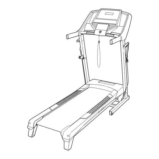
BEFORE YOU BEGIN Thank you for selecting the new PROFORM 6.0 RT reading this manual, please see the front cover of this ® treadmill. The 6.0 RT treadmill offers a selection of fea- manual. To help us assist you, note the product model tures designed to make your workouts at home more number and serial number before contacting us. -
Page 7: Part Identification Chart
PART IDENTIFICATION CHART Use the drawings below to identify small parts used for assembly. The number in parentheses below each draw- ing is the key number of the part, from the PART LIST near the end of this manual. The number following the key number is the quantity used for assembly. -
Page 8: Assembly
ASSEMBLY • To hire an authorized service technician to • Left parts are marked “L” or “Left” and right parts assemble the treadmill, call 1-800-445-2480 are marked “R” or “Right.” • Assembly requires two persons. • To identify small parts, see page 7. •... - Page 9 3. Rotate the Right and Left Rear Feet (52, 53) from the shipping position to the position shown. IMPORTANT: Do not use the treadmill with the Rear Feet (52, 53) in the shipping position. With the help of a second person, carefully tip the treadmill to the upright position so that the Rear Feet (52, 53) are resting on the floor.
- Page 10 5. Set the console assembly face down on a soft surface to avoid scratching the console Console assembly. Assembly Remove and discard the two indicated screws (B). Then, remove the Console Crossbar (97). 6. IMPORTANT: To avoid damaging the Pulse Crossbar (97), do not use power tools and do not overtighten the #10 x 3/4"...
- Page 11 7. With the help of a second person, hold the con- sole assembly near the Right Handrail (95). Insert the Upright Wire (71) through the three looped Wire Ties (75) under the console assembly. Console Next, connect the ground wire from the console Assembly assembly to the Console Ground Wire (80) on the Pulse Crossbar (97).
- Page 12 9. Attach the Latch Assembly (42) to the Left Upright (73) with two #10 x 3/4" Screws (7); start both Screws, and then tighten them. 10. Attach the Right Handle Holder (100) to the Right Upright (95) with two #8 x 3/4" Screws (79).
-
Page 13: How To Use The Treadmill
HOW TO USE THE TREADMILL HOW TO CONNECT THE POWER CORD nominal 120-volt circuit capable of carrying 15 or more amps. To avoid overloading the circuit, do Use a Surge Suppressor not plug other electrical devices, except for low- power devices such as cell phone chargers, into Your treadmill, like other electronic equipment, can be the surge suppressor or into an outlet on the same circuit. - Page 14 CONSOLE DIAGRAM FEATURES OF THE CONSOLE To turn on the power, see page 15. To use the man- ual mode, see page 15. To use a preset workout, see The treadmill console offers a selection of features page 17. To use the information mode, see page 18. To use the sound system, see page 18.
-
Page 15: To Turn On Power
HOW TO TURN ON THE POWER HOW TO USE THE MANUAL MODE IMPORTANT: If the treadmill has been exposed to 1. Insert the key into the console. cold temperatures, allow it to warm to room tem- perature before you turn on the power. If you do See HOW TO TURN ON THE POWER at the left. - Page 16 4. Change the incline of the treadmill as desired. Press the Priority Display button repeatedly until the upper display shows the information that you To change the incline of the treadmill, press the are most interested in viewing. Note: While infor- Incline increase and decrease buttons or one of mation is shown in the upper display, the same the numbered Quick Incline buttons.
-
Page 17: To Use A Preset Workout
HOW TO USE A PRESET WORKOUT At the end of each segment, a series of tones will sound and the next segment of the profile will begin 1. Insert the key into the console. to flash. If a different speed and/or incline setting is programmed for the next segment, the speed and/ See HOW TO TURN ON THE POWER on page 15. -
Page 18: Information Mode
THE INFORMATION MODE If you are using a personal CD player and the CD skips, set the CD player on the floor or another flat The console features an information mode that keeps surface instead of on the console. track of treadmill usage information and allows you to select a unit of measurement for the console. -
Page 19: How To Fold And Move The Treadmill
HOW TO FOLD AND MOVE THE TREADMILL HOW TO FOLD THE TREADMILL HOW TO MOVE THE TREADMILL Before you fold the treadmill, remove the key and Before moving the treadmill, fold it as described at the unplug the power cord. CAUTION: You must be left. -
Page 20: Maintenance And Troubleshooting
MAINTENANCE AND TROUBLESHOOTING MAINTENANCE SYMPTOM: The power turns off during use Regular maintenance is important for optimal per- a. Check the power switch (see drawing c at the left). formance and to reduce wear. Inspect and properly If the switch has tripped, wait for five minutes and tighten all parts each time the treadmill is used. - Page 21 SYMPTOM: The walking belt slows when walked on SYMPTOM: The walking belt is off-center or slips when walked on a. Use only a surge suppressor that meets all of the a. If the walking belt is off-center, first remove the specifications described on page 13.
-
Page 22: Exercise Guidelines
EXERCISE GUIDELINES Burning Fat—To burn fat effectively, you must exer- WARNING: cise at a low intensity level for a sustained period of Before beginning this time. During the first few minutes of exercise, your or any exercise program, consult your physi- body uses carbohydrate calories for energy. -
Page 23: Part List
PART LIST Model No. PFTL39115.0 R0615A Key No. Qty. Description Key No. Qty. Description 3/8" x 2 3/4" Screw Right Rear Foot M10 x 65mm Screw Left Rear Foot M4.2 x 19mm Screw Idler Roller 5/16" x 3/4" Screw Left Idler Roller Bracket M4.2 x 13mm Washer Head Screw Motor Hood M4.2 x 13mm Screw... -
Page 24: Exploded Drawing
EXPLODED DRAWING A Model No. PFTL39115.0 R0615A... - Page 25 EXPLODED DRAWING B Model No. PFTL39115.0 R0615A 23 11...
- Page 26 EXPLODED DRAWING C Model No. PFTL39115.0 R0615A...
- Page 27 EXPLODED DRAWING D Model No. PFTL39115.0 R0615A...
-
Page 28: Ordering Replacement Parts
ORDERING REPLACEMENT PARTS To order replacement parts, please see the front cover of this manual. To help us assist you, be prepared to provide the following information when contacting us: • the model number and serial number of the product (see the front cover of this manual) •...
Need help?
Do you have a question about the 6.0 RT PFTL39115.0 and is the answer not in the manual?
Questions and answers
What is this wire for
The wire in the Pro-Form 6.0 RT PFTL39115.0 connects the console assembly to the Upright Wire and Console Ground Wire. It ensures proper communication between components and grounding for safety. If the connectors are not properly connected, the console may be damaged when powered on. Additionally, wire ties secure the wiring to prevent pinching or damage.
This answer is automatically generated