
Related Manuals for Miller Dynasty 280


Summary of Contents for Miller Dynasty 280
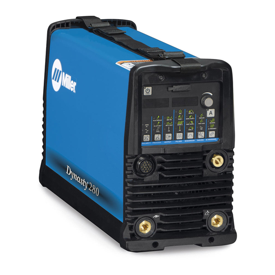
- Page 1 OM-253 086D 2013−09 Processes TIG (GTAW) Welding Stick (SMAW) Welding Description 208−575 Volt Models W/AutolineR Arc Welding Power Source Dynasty 280 Maxstar 280 Visit our website at www.MillerWelds.com...
- Page 2 We know you don’t have time to do it any other way. That’s why when Niels Miller first started building arc welders in 1929, he made sure his products offered long-lasting value and superior quality.
-
Page 3: Table Of Contents
..............SECTION 5 − DYNASTY 280 OPERATION . - Page 4 TABLE OF CONTENTS SECTION 7 − MAXSTAR 280 OPERATION ........... . . 7-1.
-
Page 5: Section 1 − Safety Precautions - Read Before Using
SECTION 1 − SAFETY PRECAUTIONS - READ BEFORE USING som 2011−10 Protect yourself and others from injury — read, follow, and save these important safety precautions and operating instructions. 1-1. Symbol Usage DANGER! − Indicates a hazardous situation which, if Indicates special instructions. - Page 6 D Do not use welder to thaw frozen pipes. FUMES AND GASES can be hazardous. D Remove stick electrode from holder or cut off welding wire at contact tip when not in use. Welding produces fumes and gases. Breathing D Wear oil-free protective garments such as leather gloves, heavy these fumes and gases can be hazardous to your shirt, cuffless trousers, high shoes, and a cap.
-
Page 7: Additional Symbols For Installation, Operation, And Maintenance
1-3. Additional Symbols For Installation, Operation, And Maintenance FIRE OR EXPLOSION hazard. BATTERY EXPLOSION can injure. D Do not install or place unit on, over, or near D Do not use welder to charge batteries or jump combustible surfaces. start vehicles unless it has a battery charging D Do not install unit near flammables. -
Page 8: California Proposition 65 Warnings
1-4. California Proposition 65 Warnings Welding or cutting equipment produces fumes or gases This product contains chemicals, including lead, known to which contain chemicals known to the State of California to the state of California to cause cancer, birth defects, or other cause birth defects and, in some cases, cancer. -
Page 9: Section 2 − Consignes De Sécurité − Lire Avant Utilisation
SECTION 2 − CONSIGNES DE SÉCURITÉ − LIRE AVANT UTILISATION fre_som_2011−10 Pour écarter les risques de blessure pour vous−même et pour autrui — lire, appliquer et ranger en lieu sûr ces consignes relatives aux précautions de sécurité et au mode opératoire. 2-1. - Page 10 Il reste une TENSION DC NON NÉGLIGEABLE dans LE SOUDAGE peut provoquer un les sources de soudage onduleur UNE FOIS incendie ou une explosion. l’alimentation coupée. Le soudage effectué sur des conteneurs fermés tels D Arrêter les convertisseurs, débrancher le courant électrique et que des réservoirs, tambours ou des conduites peut décharger les condensateurs d’alimentation selon les instructions provoquer leur éclatement.
-
Page 11: Dangers Supplémentaires En Relation Avec L'installation, Le Fonctionnement Et La Maintenance
ACCUMULATIONS LES BOUTEILLES peuvent exploser risquent de provoquer des blessures si elles sont endommagées. ou même la mort. Les bouteilles de gaz comprimé contiennent du gaz D Fermer l’alimentation du gaz comprimé en cas sous haute pression. Si une bouteille est endommagée, elle peut exploser. -
Page 12: Proposition Californienne 65 Avertissements
Les PIÈCES MOBILES peuvent RAYONNEMENT HAUTE causer des blessures. FRÉQUENCE (H.F.) risque provoquer des interférences. D Ne pas s’approcher des organes mobiles. D Ne pas s’approcher des points de coincement D Le rayonnement haute fréquence (H.F.) peut tels que des rouleaux de commande. provoquer des interférences avec les équi- pements de radio−navigation et de com- LES FILS DE SOUDAGE peuvent... -
Page 13: Principales Normes De Sécurité
2-5. Principales normes de sécurité Safety in Welding, Cutting, and Allied Processes, ANSI Standard Z49.1, Spectrum Way, Suite 100, Ontario, Canada L4W 5NS (phone: is available as a free download from the American Welding Society at 800-463-6727, website: www.csa-international.org). http://www.aws.org or purchased from Global Engineering Documents Safe Practice For Occupational And Educational Eye And Face Protec- (phone: 1-877-413-5184, website: www.global.ihs.com). - Page 14 OM-253 086 Page 10...
-
Page 15: Section 3 − Definitions (Ce Models)
A complete Parts List is available at www.MillerWelds.com SECTION 3 − DEFINITIONS (CE Models) 3-1. Additional Safety Symbols And Definitions Some symbols are found only on CE products. Warning! Watch Out! There are possible hazards as shown by the symbols. Safe1 2012−05 Wear dry insulating gloves. - Page 16 A complete Parts List is available at www.MillerWelds.com Do not remove or paint over (cover) the label. Safe20 2012−05 When power is applied failed parts can explode or cause other parts to explode. Safe26 2012−05 Flying pieces of parts can cause injury. Always wear a face shield when servicing unit. Safe27 2012−05 Always wear long sleeves and button your collar when servicing unit.
- Page 17 A complete Parts List is available at www.MillerWelds.com = < 60° Always lift and support unit using both handles. Keep angle of lifting device less than 60 degrees. Use a proper cart to move unit. Safe44 2012−05 Welding current creates an electric and magnetic field (EMF) around the welding circuit and welding equipment.
-
Page 18: Miscellaneous Symbols And Definitions
A complete Parts List is available at www.MillerWelds.com 3-2. Miscellaneous Symbols And Definitions Gas Tungsten Arc Shielded Metal Arc Amperes Panel−Local Welding (GTAW) Welding (SMAW) 3 Phase Static Frequency Volts Voltage Input Converter-Transformer-Rectifier Lift-Arc Start Voltage Output Circuit Breaker Remote (GTAW) Protective Earth Postflow Timer... -
Page 19: Section 4 − Installation
A complete Parts List is available at www.MillerWelds.com SECTION 4 − INSTALLATION 4-1. Serial Number And Rating Label Location The serial number and rating information for the power source is located on the top of the machine. Use the rating labels to determine input power requirements and/or rated output. - Page 20 A complete Parts List is available at www.MillerWelds.com B. Maxstar Welding Amperage Max Open Circuit Low Open-Circuit Rated Peak Striking IP Rating Range Voltage (Uo) Voltage (Uo) Voltage (Up) ♦ 1-280* 8-15*** 15KV** *Welding range for Stick process is 5-280 amperes. For TIG, the amperage range is tungsten diameter dependent (see Sections 7-4 and/or 8-3) depending on model.
-
Page 21: Duty Cycle And Overheating
A complete Parts List is available at www.MillerWelds.com 4-3. Duty Cycle And Overheating Duty Cycle is percentage of 10 min- utes that unit can weld at rated load without overheating. If unit overheats, output stops, a Help message is displayed (see Section 10-2), and cooling fan runs. -
Page 22: Selecting A Location
A complete Parts List is available at www.MillerWelds.com 4-4. Selecting A Location Line Disconnect Device Locate unit near correct input power supply. Special installation may be required where gasoline or volatile liquids are present − see NEC Article 511 or CEC Section 20. -
Page 23: Dimensions, Weights, And Mounting Options
A complete Parts List is available at www.MillerWelds.com 4-6. Dimensions, Weights, And Mounting Options A. Welding Power Source Dimensions 13-5/8 in. (346 mm) 8-5/8 in. (219 mm) 22-1/2 in. (569 mm) Weight Maxstar: 47 lb (21.3 Kg) Dynasty: 52 lb (23.6 Kg) Ref. -
Page 24: Selecting Cable Sizes
****For distances longer than 100 ft (30 m) and up to 200 ft (60 m), use direct current (DC) output only. For distances longer than those shown in this guide, call a factory applications rep. at 920-735-4505 (Miller) or 1-800-332-3281 (Hobart). -
Page 25: Connections
A complete Parts List is available at www.MillerWelds.com 4-8. Connections Turn off power before mak- ing connections. Dynasty Connections Remote Control Receptacle (See Section 4-13) Gas Out To Torch Connection Requires an 11/16 in. Wrench. Work Lead Connection TIG Torch Or Stick Electrode Holder Connection Main Power Switch Use switch to energize/de-ener-... -
Page 26: Cooler Connections
A complete Parts List is available at www.MillerWelds.com 4-9. Cooler Connections Cart and cooler may be purchased separately. 115 Volt AC Grounded Receptacle For 115 volt models, an individual branch circuit capable of carrying 15 amperes and protected by fuses or circuit breakers is recom- mended. -
Page 27: Electrical Service Guide
A complete Parts List is available at www.MillerWelds.com 4-10. Electrical Service Guide A. Electrical Service Guide For Three-Phase Operation Failure to follow these electrical service guide recommendations could create an electric shock or fire hazard. These recommenda- tions are for a dedicated circuit sized for the rated output and duty cycle of the welding power source. In dedicated circuit installations, the National Electrical Code (NEC) allows the receptacle or conductor rating to be less than the rating of the circuit protection device. -
Page 28: Connecting Three-Phase Input Power
A complete Parts List is available at www.MillerWelds.com 4-11. Connecting Three-Phase Input Power = GND/PE Earth Ground Tools Needed: input2 2011−03 − 803 766-C / Ref. 805 496-A OM-253 086 Page 24... - Page 29 A complete Parts List is available at www.MillerWelds.com 4-11. Connecting Three-Phase Input Power (Continued) primary voltage being applied. Check input Input Conductors (L1, L2 And L3) Installation must meet all National and voltage available at site. This unit can be con- Local Codes −...
-
Page 30: Connecting Single-Phase Input Power
A complete Parts List is available at www.MillerWelds.com 4-12. Connecting Single-Phase Input Power =GND/PE Earth Ground Tools Needed: input1 2011−03 − 803 766-C / Ref. 805 496-A OM-253 086 Page 26... - Page 31 A complete Parts List is available at www.MillerWelds.com 4-12. Connecting Single-Phase Input Power (Continued) nected to any input power between 208−575 Disconnect Device (switch shown in the Installation must meet all National and VAC without removing cover to relink the OFF position) Local Codes −...
-
Page 32: Remote 14 Receptacle Information
A complete Parts List is available at www.MillerWelds.com 4-13. Remote 14 Receptacle Information Socket* Socket Information Contactor control +15 volts DC, referenced to G. 15 VOLTS DC OUTPUT Contact closure to A completes 15 volts DC CONTACTOR contactor control circuit and enables output. Output to remote control;... -
Page 33: Software Installation
Go to MillerWelds.com/TIG- to the card, and the meter displays go blank. The update time may vary Software to download the up to three minutes. Do Not re- latest software upgrades. Dynasty 280 DX Shown 805 496-A Notes OM-253 086 Page 29... -
Page 34: Section 5 − Dynasty 280 Operation
A complete Parts List is available at www.MillerWelds.com SECTION 5 − DYNASTY 280 OPERATION 5-1. Dynasty 280 Controls 247 222-A Standby Button Volt Meter Use to turn machine on and off for daily op- Displays actual voltage when voltage is Output ON Indicator eration. -
Page 35: Accessing Control Panel Menu: Ac Tig
A complete Parts List is available at www.MillerWelds.com 5-2. Accessing Control Panel Menu: AC TIG Menu Button Press Menu button to cycle through parameters that can be set. Parameter Display Setting Display Encoder Rotate Encoder to adjust parameter setting. Parameter automatically returns to amperage setting 15 seconds after Encoder is inactive. -
Page 36: Accessing Control Panel Menu: Dc Tig
A complete Parts List is available at www.MillerWelds.com 5-3. Accessing Control Panel Menu: DC TIG Menu Button Press Menu button to cycle through para- meters that can be set. Parameter Display Setting Display Encoder Rotate Encoder to adjust parameter setting. Parameter automatically returns to am- perage setting 15 seconds after En- coder is inactive. -
Page 37: Accessing User Setup Menu: Ac And Dc Tig
A complete Parts List is available at www.MillerWelds.com 5-5. Accessing User Setup Menu: AC And DC TIG Menu Button Press and hold Menu button for ap- proximately two seconds to access machine configuration menus. Use Menu button to cycle through para- meters that can be set. -
Page 38: Accessing User Setup Menu: Ac And Dc Stick
A complete Parts List is available at www.MillerWelds.com 5-6. Accessing User Setup Menu: AC And DC Stick Menu Button Press and hold Menu button for ap- proximately 2 seconds to access machine configuration menus. Use Menu button to cycle through para- meters that can be set. -
Page 39: Section 6 − Dynasty 280Dx Operation
A complete Parts List is available at www.MillerWelds.com SECTION 6 − DYNASTY 280DX OPERATION 6-1. Dynasty 280 DX Controls 227 220-C Memory Card Port And Indicator Amperage Control For all front panel switch pad controls: This port is used to add features to the ma-... -
Page 40: Accessing Control Panel Menu
A complete Parts List is available at www.MillerWelds.com 6-2. Accessing Control Panel Menu Amperage Button Parameter Display Setting Display Encoder Rotate Encoder to adjust paramet- er setting. Amperage Control Controls the welding amperage output. Limits the maximum output of a remote amperage device. 150A 150A 247 220-C... - Page 41 A complete Parts List is available at www.MillerWelds.com Pulse Control *PRO−SET provides PROfessionally developed SETtings for the weld process PRO−SET flashes one time and reveals the professional setting for the parameter. Pulsing is available in the TIG process. Controls can be adjusted while welding.
-
Page 42: Accessing User Setup Menu
A complete Parts List is available at www.MillerWelds.com 6-3. Accessing User Setup Menu Amperage Button Gas/Dig Button Parameter Display Setting Display Encoder To access the User Functions, press and hold the Amperage (A) and the Gas/DIG controls until USER MENU is displayed. To scroll through the user menu functions, press and release the Gas/DIG control. -
Page 43: Selecting General (Gen) Tungsten To Change Programmable Tig Starting Parameters
A complete Parts List is available at www.MillerWelds.com 6-4. Selecting General (GEN) Tungsten To Change Programmable TIG Starting Parameters Encoder Control Parameter Display Amperage Button Once inside the machine set up menu, tungsten parameter values can be manually changed by press- ing the Amperage switch pad to step through each adjustable para- meter. -
Page 44: Section 7 − Maxstar 280 Operation
A complete Parts List is available at www.MillerWelds.com SECTION 7 − MAXSTAR 280 OPERATION 7-1. Maxstar 280 Controls HF START LIFT ARC Hold for Setup Schedule 1 Schedule 2 247 223-A Memory Card Port And Indicator Menu Button For all front panel switch pad controls: Press button to scroll through available press switch pad to turn on light and en- parameters for the selected process. -
Page 45: Accessing Control Panel Menu: Dc Tig Hf And Lift Arc
A complete Parts List is available at www.MillerWelds.com 7-2. Accessing Control Panel Menu: DC TIG HF And Lift Arc Menu Button Press Menu button to cycle through parameters that can be set. Parameter Display Setting Display Encoder Rotate Encoder to adjust paramet- er setting. -
Page 46: Accessing Control Panel Menu: Dc Stick
A complete Parts List is available at www.MillerWelds.com 7-3. Accessing Control Panel Menu: DC Stick Menu Button Press Menu button to cycle through parameters that can be set. Parameter Display Setting Display Encoder Rotate Encoder to adjust paramet- er setting. Parameter automatically re- turns to amperage setting 15 seconds after Encoder is inact-... -
Page 47: Accessing User Setup Menu: Dc Tig And Lift-Arc
A complete Parts List is available at www.MillerWelds.com 7-4. Accessing User Setup Menu: DC TIG And Lift-Arc Menu Button Press and hold Menu button for ap- proximately 2 seconds to access machine configuration menus. Use Menu button to cycle through para- meters that can be set. -
Page 48: Accessing User Setup Menu: Dc Stick
A complete Parts List is available at www.MillerWelds.com 7-5. Accessing User Setup Menu: DC Stick Menu Button Press and hold Menu button for ap- proximately 2 seconds to access machine configuration menus. Use Menu button to cycle through para- meters that can be set. Parameter Display Setting Display Encoder... -
Page 49: Section 8 − Maxstar 280Dx Operation
A complete Parts List is available at www.MillerWelds.com SECTION 8 − MAXSTAR 280DX OPERATION 8-1. Maxstar 280 DX Controls 227 220-C Encoder Control Ammeter For all front panel switch pad controls: Use encoder control in conjunction with ap- press switch pad to turn on light and en- Displays actual amperage while welding and plicable front panel function switch pads to able function. -
Page 50: Accessing Control Panel Menu
A complete Parts List is available at www.MillerWelds.com 8-2. Accessing Control Panel Menu Amperage Button Parameter Display Setting Display Encoder Rotate Encoder to adjust paramet- er setting. The Amperage Control controls the welding amperage output, and lim- its the maximum output of a remote amperage device. - Page 51 A complete Parts List is available at www.MillerWelds.com *PRO−SET provides PROfessionally developed SETtings for the weld process. PRO−SET flashes one time and reveals the professional setting for the parameter. Pulse Control Pulsing is available while in the TIG process. Controls can be adjusted while welding. Reduces heat input to minimize distortion and in- crease travel speed.
-
Page 52: Accessing User Setup Menu
A complete Parts List is available at www.MillerWelds.com 8-3. Accessing User Setup Menu Amperage Button Gas/Dig Button Parameter Display Setting Display Encoder To access the User functions, press and hold the Amperage (A) and the Gas/DIG controls until USER MENU is displayed. To scroll through the user menu functions, press and release the Gas/DIG control. -
Page 53: Section 9 − Advanced Menu Functions
Setting Display Encoder Rotate Encoder to adjust paramet- er setting. TECH MENU Dynasty 280 shown, Maxstar menus are the same. Menu or- der may vary. To exit user menu, press and hold menu button approximately one second, or turn power off. -
Page 54: Accessing Tech Menu For Dynasty/Maxstar 280Dx Models
A complete Parts List is available at www.MillerWelds.com 9-2. Accessing Tech Menu For Dynasty/Maxstar 280DX Models Amperage Button Gas/Dig Button Press and hold Amperage and Gas/Dig buttons for approximately 2 seconds to scroll past User Menu to Tech Menu. Use Gas/Dig button to cycle through parameters that can be set. - Page 55 A complete Parts List is available at www.MillerWelds.com [ARC] [T/CY] Arc Timer: Monitors hours, minutes, and cycles of valid arc on. To view these different elements, rotate encoder. To reset, ro- tate encoder until [RESET] [YES] is displayed. Press Menu button to display [RESET] [Done]. Displays turn to [000] [000]. [ERR] [LOG] Error Log: Use to view last eight logged error events.
-
Page 56: Sequencer And Weld Timer For Dx Model
A complete Parts List is available at www.MillerWelds.com 9-3. Sequencer And Weld Timer For DX Model Sequencer Control With Weld Timers ON INTL This function is available while using the TIG process, but is disabled if a remote foot or fin- gertip control is connected while in the RMT STD mode. -
Page 57: Output Control And Trigger Functions For Dx Models
A complete Parts List is available at www.MillerWelds.com 9-4. Output Control And Trigger Functions For DX Models A. Remote (Standard), 2T, And 4TE Torch Trigger Operation Current (A) Main Amps Initial Slope Final Slope Initial Amps Final Amps Postflow Preflow Time Standard P &... - Page 58 A complete Parts List is available at www.MillerWelds.com 3T Specific Trigger Method Current (A) Remote Trigger Operation Preflow Initial Amps /Initial Slope Main Amps Final Slope /Final Amps Postflow * Arc can be extinguished at any time by pressing and releasing both initial and final switches, or by lifting the torch and breaking the arc. 3T (Specific Trigger Operation) Operation: C.
- Page 59 A complete Parts List is available at www.MillerWelds.com C. 4T And 4TL Specific Trigger Method 4T Application: Use 4T trigger method when the functions of a remote current con- trol are desired, but only a remote on/off control is available. 4T allows the operator to toggle be- tween weld current and final cur- 4T Torch Trigger Operation...
-
Page 60: Lockout Functions
A complete Parts List is available at www.MillerWelds.com 9-5. Lockout Functions See Section 9-2 for information on how to access Lockout Functions. There are four (1−4) different lockout levels. Each successive level allows the operator more flexibility. Before activating lockout levels, be sure that all procedures and para- meters are established. -
Page 61: Section 10 − Maintenance And Troubleshooting
A complete Parts List is available at www.MillerWelds.com SECTION 10 − MAINTENANCE AND TROUBLESHOOTING 10-1. Routine Maintenance Disconnect power before maintaining. Maintain more often during severe conditions. A. Welding Power Source Δ = Repair n = Check Z = Change ~ = Clean l = Replace * To be done by Factory Authorized Service Agent... -
Page 62: Voltmeter/Ammeter Display Messages
A complete Parts List is available at www.MillerWelds.com 10-2. Voltmeter/Ammeter Display Messages Release Trigger Latching Errors: RELE CHEK INPT WELD CABL TRIG Latching Errors: O.M. Un Short Output HORT UN S Not Valid OUTP VALD Over Temperature Error Lock Level OVER TEMP LOCK LEV1... -
Page 63: Troubleshooting Table
A complete Parts List is available at www.MillerWelds.com 10-3. Troubleshooting Table Trouble Remedy No weld output; unit completely Place line disconnect switch in On position (see Section 4-11 or 4-12). inoperative. Check and replace line fuse(s), if necessary, or reset circuit breaker (see Section 4-11 or 4-12). Check for proper input power connections (see Section 4-11 or 4-12). -
Page 64: Blowing Out Inside Of Unit
A complete Parts List is available at www.MillerWelds.com 10-4. Blowing Out Inside of Unit Do not remove case when blowing out inside of unit. To blow out unit, direct airflow through front and back louvers as shown. 805 497-A 10-5. Coolant Maintenance Disconnect input power be- fore maintaining. -
Page 65: Section 11 − Parts List
A complete Parts List is available at www.MillerWelds.com SECTION 11 − PARTS LIST 11-1. Recommended Spare Parts Dia. Part Mkgs. Description Quantity Recommended Spare Parts ....239494 . -
Page 66: Section 12 − Electrical Diagrams
A complete Parts List is available at www.MillerWelds.com SECTION 12 − ELECTRICAL DIAGRAMS 255980-A Figure 12-1. Circuit Diagram For Dynasty 280 OM-253 068 Page 62... - Page 67 A complete Parts List is available at www.MillerWelds.com 255 981-B Figure 12-2. Circuit Diagram For Maxstar 280 OM-253 086 Page 63...
-
Page 68: Section 13 − High Frequency
A complete Parts List is available at www.MillerWelds.com SECTION 13 − HIGH FREQUENCY 13-1. Welding Processes Requiring High Frequency High-Frequency Voltage TIG − helps arc jump air gap between torch and workpiece and/ or stabilize the arc. Work high_freq 5/10 − S-0693 13-2. -
Page 69: Recommended Installation To Reduce Hf Interference
A complete Parts List is available at www.MillerWelds.com 13-3. Recommended Installation To Reduce HF Interference Weld Zone 50 ft (15 m) 50 ft (15 m) Ground all metal ob- jects and all wiring in welding zone using #12 AWG wire. Ground workpiece if required by... -
Page 70: Machines
A complete Parts List is available at www.MillerWelds.com SECTION 14 − SELECTING AND PREPARING A TUNG- STEN FOR DC OR AC WELDING WITH INVERTER MACHINES gtaw_Inverter_2011-06 Whenever possible and practical, use DC weld output instead of AC weld output. 14-1. Selecting Tungsten Electrode ( Wear Clean Gloves To Prevent Contamination Of Tungsten Not all tungsten electrode manufacturers use the same colors to identify tungsten type. -
Page 71: Section 15 − Tig Procedures
A complete Parts List is available at www.MillerWelds.com SECTION 15 − TIG PROCEDURES gtaw_Inverter_2011-06 For additional resources on welding, visit http://www.millerwelds.com/resources/improving−your−skills 15-1. Lift-Arc And HF TIG Start Procedures Lift-Arc Start When Lift-Arct button light is On, start arc as follows: TIG Electrode Workpiece Touch tungsten electrode to work-... -
Page 72: Pulser Control
A complete Parts List is available at www.MillerWelds.com 15-2. Pulser Control Pulser Control Pulsing is available while using the TIG process. Con- trols can be adjusted while welding. Press switch pad to enable pulser. ON - When illuminated, this LED indicates the pulser is Press switch pad until desired parameter LED is illumi- nated. -
Page 73: Section 16 − Stick Welding (Smaw) Guidelines
A complete Parts List is available at www.MillerWelds.com SECTION 16 − STICK WELDING (SMAW) GUIDELINES 16-1. Electrode and Amperage Selection Chart 6010 DEEP 3/32 MIN. PREP, ROUGH HIGH SPATTER 6011 DEEP 6010 5/32 & 6013 EP,EN GENERAL 3/16 6011 7/32 SMOOTH, EASY, 7014 EP,EN... - Page 74 Notes TM-216 869 Page 70 Dynasty 350/700, Maxstar 350/700...
- Page 75 Effective January 1, 2013 (Equipment with a serial number preface of MD or newer) This limited warranty supersedes all previous Miller warranties and is exclusive with no other guarantees or warranties expressed or implied. Warranty Questions? LIMITED WARRANTY − Subject to the terms and conditions below, 6 Months —...
- Page 76 Contact the Delivering Carrier to: File a claim for loss or damage during shipment. For assistance in filing or settling claims, contact your distributor and/or equipment manufacturer’s Transportation Department. © ORIGINAL INSTRUCTIONS − PRINTED IN USA 2013 Miller Electric Mfg. Co. 2013−01...
Need help?
Do you have a question about the Dynasty 280 and is the answer not in the manual?
Questions and answers