Greenwood EL100 Installation Instructions Manual
Dc axial fans for kitchens, bathroom and toilets
Hide thumbs
Also See for EL100:
- Installation instructions manual (7 pages) ,
- Installation instructions manual (12 pages)

Related Manuals for Greenwood EL100


Summary of Contents for Greenwood EL100
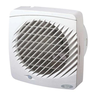
- Page 1 Environmental Slotvent EL100 & 150HT DC Axial Fans for Kitchens, Bathroom and Toilets...
-
Page 2: Operation
Operation To clean or service fan The Airvac Elite range of fans are multi speed 24V DC units offering varying extract levels up to G Remove grille: Lever off at side using coin or and exceeding Building Regulation requirements screwdriver. for kitchens, bathrooms and toilets. -
Page 3: Window Mounting
Window Mounting Ø EW100/150 EL100 Ø = 118 mm ± 1 mm EL150 Ø = 167 mm ± 1 mm EL100/150 Make sure G For window mounting do rubber cable not install fans in opening grommet is fitted onto cable windows. -
Page 4: Wall Mounting
Ø = 125mm ED150 Ø = 180 mm Ø = 125mm ED150 Ø = 180 mm External Grille Ducting EL100/150 Make sure rubber cable grommet is fitted onto cable before threading cable through fan back plate. SEE PAGE 10 FOR WIRING INSTRUCTIONS... -
Page 5: Ceiling Mounting
Ceiling Mounting Ø B EL100 EL150 Ø 12 for cable Make sure rubber cable grommet is fitted onto cable before threading cable through back plate EL100/150 Flexible Ducting External Grille or Airbrick EG100/RAB G Cut an opening through the ceiling for the fan and electrical cable. -
Page 6: Wiring Diagrams
Wiring Details for Fan Isolator Only Wiring Diagrams The electrical connections must be carried out Mains To Fan 24 V 230 V ~ 50 Hz by a qualified electrical engineer in accordance 25 mm with IEE or local regulations. 2–Wire Connection WARNING: Isolate electricity supply before 1 2 3 6 mm... - Page 7 Sensor / Timer Adjustments Clockwise to increase and anti- clockwise to decrease time. Timer Adjustments PSU Set Up – Minimum time The output voltage of the PSU can be adjusted + Maximum time to provide varying levels of power consumption and extract performance.
Need help?
Do you have a question about the EL100 and is the answer not in the manual?
Questions and answers
**** has begun to make squeaky squeal noise when operating, have the bearings gone and it’s time to replace?