Table of Contents
Advertisement
Advertisement
Table of Contents

Related Manuals for Greenwood Vireo HR155WM


Summary of Contents for Greenwood Vireo HR155WM
- Page 1 Vireo HR155WM / HR155CM / HR185WM Mechanical Ventilation with Heat Recovery Installation Instructions Vireo HR155WM Vireo HR155CM Vireo HR185WM Commissioning Data: To be completed by the Commissioning Engineer. Refer to User/Homeowner Guide also supplied.
-
Page 2: Table Of Contents
Positioning ....................Configuration....................Mounting ..................... Access Dimension for Maintenance............Condensate Drain ..................Ducting Guidelines ..................Electrical ..................... Wiring The Unit ................... Connecting to the BMS ................On-Site Commissioning ................Declaration of Performance (DOP) ............. Guarantee ....................Vireo HR155WM Vireo HR155CM Vireo HR185WM... -
Page 3: General Description / Physical Specifications
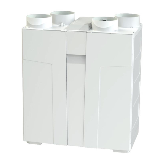
1.0 General Description / Physical Specifications Overview The Vireo HR155WM / HR155CM / HR185WM is a ventilation system designed to provide improved indoor 1.1.1 air quality in dwellings. As a whole house system, the unit continuously extracts air from the non-habitable rooms and supplies fresh, filtered air to habitable rooms. Heat that is recovered from the air drawn from the bathrooms and kitchen is passed through a heat exchanger and the heat that is recovered is transferred, to temper the supply air in habitable rooms to provide a comfortable indoor environment. A boost speed facility is provided to increase the ventilation rate, e.g. when cooking or showering, providing a 1.1.2 comfortable indoor environment. A GS2 Switch Live boost switch or a GRC1 boost and alert controller can be used to provide this operation (See Section 2.8.5 Electrical). This product features on PCDB as a high efficiency version and part of the process requires the Installation 1.1.3 Checklist for MVHR products to be completed and submitted to building control, available at www.ncm-pcdb.org.uk along with all other relevant paperwork. - Page 4 This product may not be treated as household waste. Instead it should be handed to an appropriate collection point for the recycling of electrical and electronic equipment. For more detailed information about the recycling of this product, please contact your local council office or your household waste disposal service. Physical Specifications Vireo HR155WM side Vireo HR155WM Vireo HR155WM front 1.2.1 Front View Side View Vireo HR155CM front Vireo HR155CM 1.2.2...
-
Page 5: Installation Instructions
Vireo HR185WM front Vireo HR185WM side Vireo HR185WM 1.2.3 Front View Side View 2.0 Installation Instructions General Preparation The Vireo HR155WM / HR155CM unit is supplied with 4 x 125mmØ spigots. 2.1.1 125mm ducting with connectors can be used (see Ancillary Section page 3) • to provide performance levels required for compliance with Building Regulations. The Vireo HR185WM unit is supplied with 4 x 150mmØ spigots. 2.1.2 150mm ducting with connectors can be used (see Ancillary Section page 3) • to provide performance levels required for compliance with Building Regulations. -
Page 6: Configuration
Maintenance). The unit can be configured for right and left hand installation at a touch of a button by following the steps 2.2.5 within the Commissioning Wizard (See Section 3.1.4 Commissioning Wizard) and does not require any (See Figures overleaf for ducting configuration). internal changes. Configuration Note: To change the handing of the unit, follow the simple steps within the Commissioning Wizard (See Section 3.0). Automatically done for you via software. Vireo HR155WM 2.3.1 INTAKE SUPPLY EXTRACT EXHAUST EXHAUST EXTRACT SUPPLY INTAKE Right Hand (factory setting) Left Hand... -
Page 7: Mounting
Mounting The Vireo HR155WM / HR185WM unit is supplied with one wall fixing bracket. The bracket is a long strip and 2.4.1 has two adjustable fixing points located at the end of the bracket. Screws and fixings not supplied. Proceed to align the wall bracket taking into account the available wall space to mount the unit, ensuring that 2.4.2 the wall can support 20kg (Vireo HR155WM) and 30kg (Vireo HR185WM). Use a spirit level to assist mounting and levelling the bracket. Securely fix bracket to wall using 2.4.3 suitable fixings.e ‘V’ slots located top and bottom of bracket to mar The unit fixes to the wall bracket by slotting the bracket attached to the back of the unit and hooking 2.4.4 into place. Fixing Bracket Note: • Fixing Bracket height will be critical in kitchen cupboard. There should be no movement once correctly located and the filters should be accessible •... - Page 8 The unit fixes to the ceiling bracket by slotting the bracket attached to the back of the unit and sliding into 2.4.7 place. First ensure connection is achieved on the “securely” fixed bracket (See Figure 2) and push unit up to ceiling, slide “loosely” fixed bracket to connect with the bracket on the back of the unit (See Figure Securely locate brackets together Figure 2 Figure 3 Tighten loose screws until the unit is securely fitted (See Figure 4), add an additional two screws to the 2.4.8 outside slots. Screw points for both brackets are shown in Figure Figure 4 Figure 5 Note: There should be no movement once correctly located and the filters should be accessible •...
-
Page 9: Access Dimension For Maintenance
Access Dimension for Maintenance HR155WM Footprint of Vireo HR155WM - (Wall Mounted) 2.5.1 500mm Top View HR155CM Footprint of Vireo HR155CM - (Ceiling Mounted) 2.5.2 500mm Side View Footprint of Vireo HR185WM - (Wall Mounted) 2.5.3 HR185WM 600mm Top View... -
Page 10: Condensate Drain
In some instances, a condensate connecting point will already be provided as part of the building design. 2.6.3 The position of this point, relative to where the unit is to be installed should be checked for any connection misalignment and any necessary adjustment made before proceeding any further. HR155WM HR155WM Vireo HR155WM / HR185WM Vireo HR155WM Vireo HR155WM HR155WM/185WM Condensate connection Figure 6 - Close up view Figure 7 - Front View Figure 8 - Side View of condensate... -
Page 11: Ducting Guidelines
Figure 12 - Front View Figure 13 - Side View of condensate Ducting Guidelines Please refer to design drawings for proposed ducting layout. 2.7.1 Four spigots are provided for connection of the ducting; 2.7.2 • Vireo HR155WM / HR155CM - 125mm nominal diameter • Vireo HR185WM - 150mm nominal diameter. Ductwork should be securely connected to spigots. Failure to do this will cause unnecessary air leakage and impair performance. Ducting must be connected to all four spigots according to right or left hand configuration (See Section 2.3 for Configuration). Where ducts are exposed in unheated areas, such as roof spaces, they must be insulated with at least 25mm 2.7.3 of insulation. -
Page 12: Electrical
WARNING: The appliance MUST be earthed. 2.8.1 All wiring must conform to BS7671: IEE Wiring Regulations. The installation must be carried out by a qualified Electrician. 2.8.2 All units are suitable for a 230V ~ 50Hz single phase supply fused at 3A. 2.8.3 A triple-pole switch having a minimum contact separation of 3.0mm must be used to provide isolation for 2.8.4 the unit. The recommended switches for use with this product are the Greenwood Airvac; 2.8.5 - Optional 2-position hardwired switch GRC1 - Optional boost + system status hardwired remote switch (See Figure 14 for wiring diagram) Controller Switch Type Speeds 2 - position rocker Low (I) High (II) -
Page 13: Wiring The Unit
Light Switch Isolating Switch Figure 14 - Wiring Specification 2.9.1 Wiring Enhanced Control Options via the Building Management System (BMS) To wire into to the BMS connector within the Vireo unit, first remove the electrical wiring cover as per 2.9.2 Fig. 15 -17 below then locate the BMS connector on the PCB. Vireo HR155WM Vireo HR185WM Vireo HR155CM HR185WM HR155CM HR155WM Supply cord PCB CLOSEUP Figure 15 - Top View... - Page 14 Vireo Unit BMS Connector VOLT FREE CONTACTS GIVING FAULT IDENTIFICATION BOOST GND GRC1 BATHROOM SW. GREENWOOD (Volt free contact) REMOTE CONTROLLER NOT RATED FOR (GRC1 - Option) MAINS SWITCHING 2 core cable, 0.5mm Max. (up to 15 metres) Figure 19 - GRC1 Controller Figure 20 - BMS Wiring Diagram Note: Only one GRC1 boost and status controller can be installed with the Vireo unit. Additional boost...
- Page 15 When wiring has been completed apply cable clamp and retain the cable sheath securely in place by 2.9.4 tightening the cable clamp down with screw fixings. 1 2 3 1 2 3 Pre-wired supply cord not shown Figure 21 - Securing BMS Wiring (Cable not supplied) Refit electrical cover, taking care gasket seal underneath is seated correctly and cable is not trapped. 2.9.5 Pre-wired supply cord not shown Figure 22 - Electrical Cover Attached (Cable not supplied)
-
Page 16: On-Site Commissioning
On-Site Commissioning This section covers set-up, configuration of the unit for installation and altering pre-set factory settings. 3.1.1 For instructions on how to operate the LCD display user menu, maintenance options and indicator warning information, please refer to the User / Homeowner Guide. Once the wiring connections have been checked, switch the mains supply on and check that the system is 3.1.2 operating correctly. Lift cover of commissioning wizard located at the top of the unit. Upon connection of electrical supply, the commissioning wizard will automatically turn on (See Section 3.1.4). Integral LCD Display 3.1.3 Control Information Panel Control Button Summer Frost Service/Fault ByPass Protection SETUP COMMISSIONING WIZARD SETUP COMMISSIONING WIZARD Below are examples/explanations of what you would see through the Commissioning Wizard. Below are examples/explanations of what you would see through the Commissioning Wizard. Example 1: Function selection screen O R T C O N F I G :... - Page 17 S U P P L Y L O W Factory airflow set at 33%, rotate button to required airflow % < 3 3 % > Press button to select Rotate button and choose FWD to move to next section or BACK to return to set-up Press button to select Step 6 Greenwood HumidiSMART Set-up H U M I D I S M A R T Rotate button to choose either ON or OFF < O N > Press button to select Rotate button and choose FWD to move to next section or BACK to return to set-up...
- Page 18 Valve Set-up 3.1.5 Switch the unit to the highest operating position. • Close external windows and doors. • With the system operating in high mode, proceed to open the extract valves to their maximum. • Measure the total air volume at the extract valves. • Regulate the extract valves to the required flow per room. • Switch the unit to low speed to confirm desired extract rate is achieved. • It should normally not be necessary to adjust the extract valves further. Repeat tests for supply air valves. • Once the unit is commissioned check that the system is operating correctly by turning the hardwired switch to 3.1.6 the differing settings, i.e. the GS2 switch or GRC1 controller will activate the unit between low and high speed settings. Performance levels can be verified at both extract and supply air valves using an appropriate • method such as a rotating vane anemometer and air cone kit. Record airflow rates for room extract and supply air valves for low and high speeds within the • separate User/Homeowner guide that should be incorporated into the Home Information Pack for the homeowner to keep. Refer to performance graphs for Vireo HR155WM / HR155CM / HR185WM airflow characteristics • (See Section 3.1.7 and 3.1.8). Note: All settings are stored within the Vireo unit’s memory and should NOT be lost in the event of a power failure.
- Page 19 To Re-activate Commissioning Set-up Wizard 3.1.9 In the event that the unit needs to be adjusted once the commissioning wizard has been completed; Press the control button to activate the unit. • Rotate button until the screen displays "Setup Menu". < S E T U P M E N U > • p a s s w o r d e n t r y Press button to select. • • Enter Password "1010" by rotating the button to the respective number and press to select (this has to be completed for each P A S S W O R D number prior to continuing).
-
Page 20: Declaration Of Performance (Dop)
4.0 Declaration of Performance Declaration of Performance Residential Ventilation Unit Greenwood Vireo HR155WM Greenwood Airvac Greenwood Airvac Greenwood Airvac Greenwood Airvac Supplier Name or Trade Mark Manual Control Clock Control Central Demand Control Local Demand Control Supplier Model Identifier and Options Installed... - Page 21 Declaration of Performance Residential Ventilation Unit Greenwood Vireo HR155CM Greenwood Airvac Greenwood Airvac Greenwood Airvac Greenwood Airvac Supplier Name or Trade Mark Manual Control Clock Control Central Demand Control Local Demand Control Supplier Model Identifier and Options Installed (via manual switch)
- Page 22 Declaration of Performance Residential Ventilation Unit Greenwood Vireo HR185WM Greenwood Airvac Greenwood Airvac Greenwood Airvac Greenwood Airvac Supplier Name or Trade Mark Manual Control Clock Control Central Demand Control Local Demand Control Supplier Model Identifier and Options Installed (via manual switch)
-
Page 23: Guarantee
5.0 The Guarantee Period This Greenwood product (Vireo HR155WM / HR155CM / HR185WM) has a 2 Year Guarantee. 5.1.1 This does not affect your statutory rights. 5.1.2 Full details available on request from +44 (0)1276 408404 or 5.1.3 www.greenwood.co.uk / info@greenwood.co.uk... - Page 24 All information is believed correct at time of going to press. E&OE. All goods are sold according to Zehnder Group UK Ltd’s Standard Zehnder Group UK Limited Conditions of Sale which are available on request. All dimensions referred to are in millimetres unless otherwise stated. Unit 4, Watchmoor Point, Zehnder Group UK Ltd reserves the right to change Camberley, Surrey, GU15 3AD specifications and prices without prior notice. Customer Services: 01276 408404 Technical Services: 01276 408402 © Copyright Zehnder Group UK Ltd 2015 Email: info@greenwood.co.uk Web: www.greenwood.co.uk 05.10.1049 Issue 3 December 2015...
Need help?
Do you have a question about the Vireo HR155WM and is the answer not in the manual?
Questions and answers