
Related Manuals for Miller Spectrum 2050


Summary of Contents for Miller Spectrum 2050
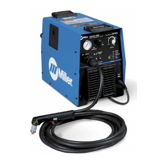
- Page 1 OM-2228 198 628R 2010−04 Processes Air Plasma Cutting and Gouging Description Air Plasma Cutter Spectrum 2050 (55 Amp) File: Plasma Cutters Visit our website at www.MillerWelds.com...
- Page 2 We know you don’t have time to do it any other way. That’s why when Niels Miller first started building arc welders in 1929, he made sure his products offered long-lasting value and superior quality.
-
Page 3: Table Of Contents
..............4-10. Wiring Optional 240 Volt Plug (119 172) For Connection To Miller Bobcat Or... -
Page 5: Section 1 − Safety Precautions - Read Before Using
SECTION 1 − SAFETY PRECAUTIONS - READ BEFORE USING pom_2010−03 Protect yourself and others from injury — read and follow these precautions. 1-1. Symbol Usage DANGER! − Indicates a hazardous situation which, if Indicates special instructions. not avoided, will result in death or serious injury. The possible hazards are shown in the adjoining symbols or explained in the text. -
Page 6: Electric Shock Can Kill
FUMES AND GASES can be hazardous ELECTRIC SHOCK can kill. SIGNIFICANT DC VOLTAGE exists in Cutting produces fumes and gases. Breathing inverter power sources AFTER the re- these fumes and gases can be hazardous to your health. moval of input power. Keep your head out of the fumes. -
Page 7: Additional Symbols For Installation, Operation, And Maintenance
1-3. Additional Symbols For Installation, Operation, And Maintenance HOT PARTS can burn. FALLING EQUIPMENT can injure. D Do not touch hot parts bare handed. D Use lifting eye to lift unit only, NOT running gear, gas cylinders, or any other accessories. D Allow cooling period before working on equipment. -
Page 8: California Proposition 65 Warnings
1-4. California Proposition 65 Warnings For Gasoline Engines: Welding or cutting equipment produces fumes or gases which contain chemicals known to the State of California to Engine exhaust contains chemicals known to the State of cause birth defects and, in some cases, cancer. (California California to cause cancer, birth defects, or other reproduc- Health &... -
Page 9: Section 2 − Consignes De Sécurité − Lire Avant Utilisation
SECTION 2 − CONSIGNES DE SÉCURITÉ − LIRE AVANT UTILISATION pom_2010−03fre Se protéger et protéger les autres contre le risque de blessure — lire et respecter ces consignes. 2-1. Signification des symboles DANGER! − Indique une situation dangereuse qui si on Indique des instructions spécifiques. - Page 10 D Assurez−vous que le fil de terre du cordon d’alimentation est cor- D Ayez recours à des protège−tympans ou à un serre−tête ignifuges rectement relié à la borne de terre dans la boîte de coupure ou que afin d’éviter que les étincelles n’entrent dans vos oreilles. la fiche du cordon est branchée à...
-
Page 11: Dangers Supplémentaires En Relation Avec L'installation, Le Fonctionnement Et La Maintenance
D Ne coupez pas dans un endroit près d’opérations de décapage, de LES BOUTEILLES peuvent exploser nettoyage ou de vaporisation. La chaleur et les rayons d’arc peu- si elles sont endommagées. vent réagir avec les vapeurs et former des gaz hautement toxiques et irritants. - Page 12 Les CHAMPS ÉLECTROMAGNÉTIQUES (CEM) CHARGES ÉLECTROSTATI- peuvent affecter les implants médicaux. QUES peuvent endommager les cir- cuits imprimés. D Les porteurs de stimulateurs cardiaques et autres implants médicaux doivent rester D Etablir la connexion avec la barrette de terre à distance. avant de manipuler des cartes ou des pièces.
-
Page 13: Proposition Californienne 65 Avertissements
2-4. Proposition californienne 65 Avertissements cancérogène ainsi que provoquant des malformations Les équipements de soudage et de coupage produisent des congénitales ou autres problèmes de procréation. Se laver les fumées et des gaz qui contiennent des produits chimiques mains après toute manipulation. dont l’État de Californie reconnaît qu’ils provoquent des mal- Pour les moteurs à... -
Page 14: Section 3 − Definitions
SECTION 3 − DEFINITIONS 3-1. Symbols And Definitions For Nameplate And Serial Number/Rating Label Plasma Arc Cutting Adjust Air/Gas Low Air Pressure Amperes (PAC) Pressure Light No − Do Not Do Volts Increase Temperature This Protective Earth Single Phase Constant Current Voltage Input (Ground) Percent... -
Page 15: Section 4 − Installation
SECTION 4 − INSTALLATION 4-1. Specifications For any single or three phase voltage from 208 V to 575 V, the Amperes Input at Rated Load Output is the same for 50 Hertz or 60 Hertz input power. For example, the amperes input for 230 V, 50 Hz, single-phase input power is 33 amperes. The amperes input for 230 V, 60 Hz, single-phase input power is also 33 amperes. -
Page 16: Duty Cycle And Overheating
4-2. Duty Cycle and Overheating Duty Cycle is percentage of 10 minutes that unit can cut at rated load without overheating. If unit overheats, thermostat(s) opens, output stops, and cooling fan runs. Wait fifteen minutes for unit to cool. Reduce amperage or duty cycle before cutting. -
Page 17: Serial Number And Rating Label Location
4-4. Serial Number And Rating Label Location The serial number and rating information for this product is located on the back. Use rating label to determine input power requirements and/or rated output. For future reference, write serial number in space provided on back cover of this manual. 4-5. -
Page 18: Connecting Work Clamp And Gas/Air Supply
4-6. Connecting Work Clamp and Gas/Air Supply Work Clamp Workpiece Connect work clamp to a clean, paint-free location on workpiece, as close to cutting area as possible. Use only clean, dry air with 90 to 120 psi (620 to 827 kPa) pressure. -
Page 19: Extension Cord Data
Failure to follow these electrical service guide recommendations could create an electric shock or fire hazard. These recommenda- tions are for a dedicated branch circuit sized for the rated output and duty cycle of the welding power source. Single 50 Hz Models Three Phase Phase Input Voltage (V) -
Page 20: Connecting Input Power
4-9. Connecting Input Power Check input voltage available at site. The Auto-LineE circuitry in this unit automatically adapts the power source to the primary voltage being applied, from 208 to 575 volts, single- or three- phase, 50 or 60 Hz. Input And Grounding Conductors Line Disconnect Device... -
Page 21: Wiring Optional 240 Volt Plug (119 172) For Connection To Miller Bobcat Or Trailblazer 251Nt, 280Nt, 300D Nt, 301G, Dc And 301D With A Minimum Of
4-10. Wiring Optional 240 Volt Plug (119 172) For Connection To Miller Bobcat Or Trailblazer 251NT, 280NT, 300D NT, 301G, DC And 301D With A Minimum Of 8 kVA Auxiliary Power Check input voltage available at the These instructions cover two different power cords, one with power supply. - Page 22 4-10. Wiring Optional 240 Volt Plug (119 172) For Connection To Miller Bobcat Or Trailblazer 251NT, 280NT, 300D NT, 301G, DC And 301D With A Minimum Of 8 kVA Auxiliary Power (Continued) This plasma cutting unit is not recommended for connection to a Hobart Champion 10,000.
- Page 23 4-10. Wiring Optional 240 Volt Plug (119 172) For Connection To Miller Bobcat Or Trailblazer 251NT, 280NT, 300D NT, 301G, DC And 301D With A Minimum Of 8 kVA Auxiliary Power (Continued) This plasma cutting unit is not recommended for connection to a Hobart Champion 10,000.
- Page 24 4-10. Wiring Optional 240 Volt Plug (119 172) For Connection To Miller Bobcat Or Trailblazer 251NT, 280NT, 300D NT, 301G, DC And 301D With A Minimum Of 8 kVA Auxiliary Power (Continued) This plasma cutting unit is not recommended for connection to a Hobart Champion 10,000.
-
Page 25: Section 5 − Operation
SECTION 5 − OPERATION 5-1. Controls Ref. 196 174-A / 802 185-B Rear of Unit Gas/Air Pressure Gauge Ready light comes On when unit is On to indi- consumables will be significantly re- cate that all safety shutdown systems are duced while in Expanded Metal mode. -
Page 26: Setting Gas/Air Pressure
Select desired cutting output with Output Place controls as indicated above. Only gas/ Gas/Air Pressure Adjustment Knob Control. 5-3. Using A Generator To Power The Spectrum 2050 See Section 4-10 for wiring instructions, and generator and Spectrum 2050 control settings. OM-2228 Page 22... -
Page 27: Sequence Of Operation
5-4. Sequence of Operation Do not clean torch by hitting it Inspect shield cup, tip, and electrode against a hard surface. Hitting for wear before cutting or whenever hard surfaces can damage cutting speed has been significantly torch parts and stop proper op- reduced (see torch Owner’s Manual). -
Page 28: Section 6 − Maintenance & Troubleshooting
SECTION 6 − MAINTENANCE & TROUBLESHOOTING 6-1. Routine Maintenance Disconnect power Maintain more often before maintaining. during severe conditions. n = Check Z = Change ~ = Clean l = Replace Reference * To be done by Factory Authorized Service Agent Each n Torch Tip, Electrode, n Gas/Air Pressure... -
Page 29: Trouble Lights
6-2. Trouble Lights Pressure Light Lights if gas/air pressure is below 40 PSI (276 kPa). Difficulty establishing pilot arc may indicate Turn power Off, and check for consumables need to be cleaned or replaced. proper gas/air pressure (see Section 5-2). Cup Light Lights if shield cup is loose. -
Page 30: Checking/Replacing Retaining Cup, Tip, And Electrode
6-4. Checking/Replacing Retaining Cup, Tip, And Electrode Overtightening will strip threads. Do not overtighten electrode, tip, and retaining cup during assembly. Do not cross-thread parts causing stripping. Use care during torch assembly and parts replacement. Inspect shield cup, tip, and electrode for wear before cutting or whenever cutting speed has been signifi- cantly reduced. -
Page 31: Troubleshooting
6-5. Troubleshooting Trouble Remedy No pilot arc; difficulty in establishing an Clean or replace worn consumables as necessary (see torch Owner’s Manual). arc. Check for damaged torch or torch cable (see torch Owner’s Manual). No cutting output; Power light off; Place Power switch in On position. -
Page 32: Section 7 − Electrical Diagram
SECTION 7 − ELECTRICAL DIAGRAM Figure 7-1. Circuit Diagram For Power Source OM-2228 Page 28... - Page 33 200 445-A OM-2228 Page 29...
-
Page 34: Section 8 − Parts List
SECTION 8 − PARTS LIST Hardware is common and not available unless listed. 802 184-Q Figure 8-1. Main Assembly OM-2228 Page 30... - Page 35 ..LABEL, MILLER ........
- Page 36 Item Dia. Part Mkgs. Description Quantity Figure 8-1. Main Assembly ....174 991 ..KNOB, pointer .
-
Page 37: Warranty
Drag Shield Retaining Cup Electrode Swirl Ring O-Ring 192 053 192 050 192 051 192 047 169 232 192 049 Standard Shield Cutting Apply silicone Machine 192 058 40A Tip grease (169 231) Cutting 192 052 before installing. Deflector Retaining Cup Electrode 177 888 192 050... - Page 38 Notes...
- Page 39 Effective January 1, 2010 (Equipment with a serial number preface of MA or newer) This limited warranty supersedes all previous Miller warranties and is exclusive with no other Warranty Questions? guarantees or warranties expressed or implied. LIMITED WARRANTY − Subject to the terms and conditions 90 Days —...
- Page 40 Contact the Delivering Carrier to: File a claim for loss or damage during shipment. For assistance in filing or settling claims, contact your distributor and/or equipment manufacturer’s Transportation Department. © ORIGINAL INSTRUCTIONS − PRINTED IN USA 2010 Miller Electric Mfg. Co. 2010−01...
Need help?
Do you have a question about the Spectrum 2050 and is the answer not in the manual?
Questions and answers