
Related Manuals for baxter Hillrom pro+


Summary of Contents for baxter Hillrom pro+
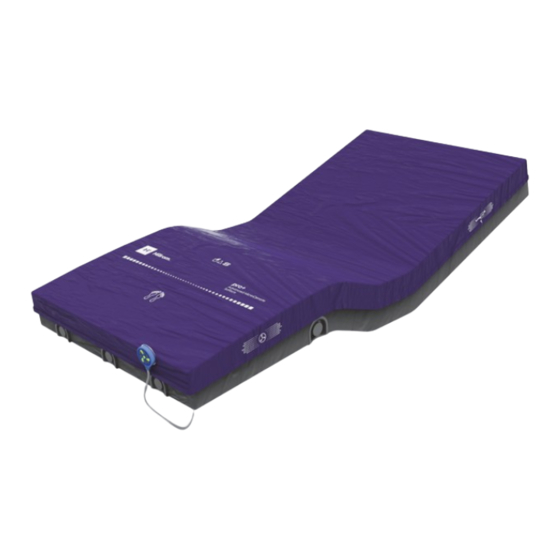
- Page 1 Hillrom pro+ SURFACE Instructions for Use Product No. P7923, P7924, P3255, and P006800 209196 REV 8...
- Page 3 QUICK VIEW LIST OF FEATURES Item Feature Page Top cover X-ray sleeve (optional) Bottom cover Microclimate Management (MCM) compo- nents (blower inlet and outlet vents) MCM status indicator (non-integrated pro+ surface only) (not shown)* Power cord NOTE: *See specific surface section for power cord type. pro+ Surface Instructions for Use (209196 REV 8)
- Page 4 C.P. 66640 APODACA MEXICO Authorized Australian Sponsor HILL-ROM PTY LTD. 1 BAXTER DRIVE OLD TOONGABBIE NSW 2146 AUSTRALIA No part of this text shall be reproduced or transmitted in any form or by any means, electronic or mechanical, including photocopying, recording, or by any information or retrieval system without written permission from Hill-Rom Services, Inc.
- Page 5 Baxter, Advanced Microclimate, CareAssist, Centrella, FlexAfoot, Graphical Caregiver Interface (GCI), Hillrom, MCM, Obstacle Detect and VersaCare are trademarks of Baxter International Inc. or its subsidiaries. Any other trademarks, product names or brand images appearing herein are the property of their respective owners.
- Page 6 NOTES: pro+ Surface Instructions for Use (209196 REV 8)
-
Page 7: Table Of Contents
Table of Contents Quick View List of Features ....... . i Intended Use . - Page 8 Table of Contents Step 3B: Install the MCM Status Indicator Mounting Kit (Rental Only) ....... . . 27 Step 4: Final Steps .
- Page 9 Table of Contents Step 3B: Install the MCM Status Indicator Mounting Kit (Rental Only) ....... . . 62 Step 4: Final Steps .
- Page 10 Table of Contents Expected Life ......... . . 95 Service Calls .
-
Page 11: Intended Use
WARNING: Warning—It is the user’s responsibility to make sure the occupant is safe if the surface is used on a bed frame not approved by Baxter. Failure to do so could cause injury or equipment damage. For use on a bed frame not approved by Baxter, evaluate the bed frame with the pro+ surface installed to make sure it is safe for patient use. -
Page 12: Safety Information
Safety Information NOTE: The CareAssist Bed supports a patient weight up to 400 lb (181 kg) and the CareAssist ES Bed supports a patient weight up to 500 lb (227 kg). To identify which version of pro+ surface you have, look at the model and serial number label. - Page 13 Safety Information WARNING: (Warnings continued) Obey these safety instructions to help prevent injury and/or equipment damage: • Warning—Do not unzip the pro+ surface while the surface is receiving AC power. Electrical shock could occur. • Warning—The potential for electrical shock exists with electrical equipment.
- Page 14 Warning—Incorrect use or handling of the power cord may cause damage to the power cord. If damage has occurred to the power cord or any of its components, immediately remove the surface from service, and contact Baxter. • Warning—Do not operate the surface in the presence of flammable gas or vapors.
-
Page 15: Symbols
Symbols WARNING: (Warnings continued) Obey these safety instructions to help prevent injury and/or equipment damage: • Warning—Connect only items that have been specified as parts of the device or compatible with the device. • Warning—The surface weighs approximately 50 lb (22.7 kg). Lift and move the surface with the handles. - Page 16 Symbols Symbol Description CareAssist Bed and Advanta 2 Bed— shows the routing and attachment locations for the surface power cord on the bed frame VersaCare Bed (P3255A01 and P3255A02)— shows the routing and attachment locations for the surface (long) power cord on the bed frame VersaCare Bed (P3255A03 and P3255A04)—...
- Page 17 Symbols Symbol Description WARNING (yellow and black) CAUTION (white and black) Must consult accompanying documents Hand wash Bleach when needed Do not tumble dry Type B applied part according to IEC 60601-1 According to IEC 60529, Rating for protection against fluid ingress and identified as equipment that is protected against spraying and splashing water MEDICAL—GENERAL MEDICAL EQUIPMENT AS TO...
- Page 18 Symbols Symbol Description Manufacturer Manufacture date Medical Device Serial Number Do not throw away— indicates the need to recycle the item in accordance with local regulations. Do not use with Oxygen Tents (can be green or blue) pro+ Surface Instruction for Use (209196 REV 8)
-
Page 19: Acronyms
Acronyms ACRONYMS Acronym Description Advanced Microclimate Technology Microclimate Management Graphical Caregiver Interface MCM Status Indicator Symbol Description MCM status indicator OFF MCM status indicator ON MCM status indicator ERROR GRAPHICAL CAREGIVER INTERFACE (GCI) (Touchscreen) These symbols only apply to the pro+ surface powered by the Centrella Smart+ Bed. -
Page 20: Surface Features
Surface Features Item Feature Page MCM status indicator ON indicator MCM status indicator OFF indicator MCM status indicator Menu Control SURFACE FEATURES OP AND OTTOM OVERS The surface top and bottom covers protect the internal components and are fluid resistant. The foot zone has a tapered foot section to help reduce pressure on the patient’s heels. -
Page 21: Linen Holders
Surface Features Rental Surface—The pro+ non- integrated surface has a status indicator that attaches to its mount on the strap that is attached to the footboard. To store the status indicator during transport or cleaning/disinfection of the surface, put the status indicator in its storage location on either side of the surface. -
Page 22: Surface Handles
Surface Features URFACE ANDLES The surface has two handles on each side of the surface. The surface handles are located on the bottom or the sides of the surface. The handles for the Centrella, Advanta 2 and CareAssist pro+ surfaces (P7923 and P7924) are on the bottom of the surface. -
Page 23: Advanced Microclimate Technology
Surface Features 10. Zip the x-ray sleeve to close and make sure the x-ray sleeve zippers are closed on both sides of the surface. 11. Make sure to lower the top cover flaps. DVANCED ICROCLIMATE ECHNOLOGY The pro+ surface uses MCM status indicator. The MCM status indicator feature operates continuously and helps decrease localized heat and moisture buildup that occurs between the patient and the surface. - Page 24 Surface Features Turn On the MCM Status Indicator Press the MCM status indicator menu control. Press On. Press OK. Set the MCM Status Indicator to Always On If the facility requests that the MCM status indicator is always on, do as follows: Press the Settings menu control.
- Page 25 Surface Features Press Mattress Features. Press Hidden. Press Accept. NOTE: If the MCM status indicator menu control is set to “Hidden”, the control will not show in the menu scroll bar. Turn Off the MCM Status Indicator Press the MCM status indicator menu control.
- Page 26 Surface Features If the MCM status indicator menu control does not show in the menu, do these: Press the Settings menu control. Press Bed Features. Press Mattress Features. d. Press Visible. Press Accept. pro+ Surface Instruction for Use (209196 REV 8)
- Page 27 Surface Features Press the MCM status indicator menu control. Press Off. Press OK. At the Home screen, the “X” MCM indicator shows, and the indicator is no longer green. pro+ Surface Instruction for Use (209196 REV 8)
-
Page 28: Installation
• Warning—It is the user’s responsibility to make sure the patient is safe if the surface is used on a frame not approved by Baxter. • Warning—Make sure that hands, arms, legs, and feet are not under the bed or between the sleep deck sections as they move. -
Page 29: Centrella Smart+ Bed
NOTES: • For the latest list of approved bed frames, contact your local Baxter representative. • Any reference to a side of the bed or surface is from the patient’s view lying in the bed on his or her back. -
Page 30: Centrella Smart+ Bed-Non-Integrated Pro+ Surface
CENTRELLA Smart+ Bed CENTRELLA Smart+ Bed—Non-Integrated pro+ Surface Tools: T10 Torx screwdriver P7924A01 pro+ Surface with x-ray, 36" (91 cm) P7924A02 pro+ Surface with x-ray, 40" (102 cm) P7924A03 pro+ Surface without x-ray, 36" (91 cm) P7924A04 pro+ Surface without x-ray, 40" (102 cm) P7924A10 pro+ Surface with x-ray, Aus/NZ 36"... - Page 31 CENTRELLA Smart+ Bed WARNING: Warning—The surface weighs approximately 50 lb (22.7 kg). Lift and move the surface with the handles. Do not twist, and seek assistance when necessary. Failure to do so could cause injury or equipment damage. 10. Use the surface handles on the bottom of the surface to lift and install the surface on the bed.
-
Page 32: Step 2: Route The Surface Power Cord
CENTRELLA Smart+ Bed Step 2: Route the Surface Power Cord Warning—Failure to route the surface power cord correctly can create a tripping hazard and/or the cord to be pinched during bed functions. Injury and/or equipment damage could occur. The surface power cord is routed along the patient-right side of the Centrella Smart+ Bed. - Page 33 CENTRELLA Smart+ Bed CENTRELLA Smart+ Bed—Surface Power Cord Routing 13. Route the power cord between the head and seat sections on the right- side of the bed, inside of the head pivot. pro+ Surface Instruction for Use (209196 REV 8)
- Page 34 CENTRELLA Smart+ Bed 14. Attach one cord magnet to the upper frame, aligned with the patient restraint bracket. 15. Attach one cord magnet to the upper frame, under the head section on the triangle bracket. 16. Attach one cord magnet to the lift arm, above the plastic insert.
-
Page 35: Step 3A: Install The Mcm Status Indicator Mounting
CENTRELLA Smart+ Bed CAUTION: Caution—To help prevent equipment damage, make sure the power cord is routed under the lift arm weldment. 18. Route the power cord under the lift arm weldment and between the head-end casters. 19. Go to the applicable section: •... - Page 36 CENTRELLA Smart+ Bed 22. Align the footboard posts to go through the holes on the flap, and install the footboard. NOTE: Make sure that the status indicator cord is not between the installed footboard and bed. 23. Make sure the status indicator can reach the mount location before you start to install the mount assembly.
-
Page 37: Kit (Rental Only)
CENTRELLA Smart+ Bed 27. Use the alcohol-based cleaner to clean the metal plate (B). Let the plate dry. 28. Remove the adhesive covering from the status indicator label (D). 29. Make sure the label (D) is in the correct orientation, then install the label on to the metal plate (B). -
Page 38: Step 4: Final Steps
CENTRELLA Smart+ Bed 34. Wrap the status indicator strap around the handle of the footboard and snap the strap together. Make sure the attachment location for the status indicator shows outward away from the patient. 35. Attach the status indicator to the status indicator label (metal disc) on the strap. - Page 39 CENTRELLA Smart+ Bed 40. Make sure the status indicator is green. NOTE: For more information about the indicator light, see “Status Indicator light” on page 30. 41. Make sure the surface foot end flap is secured by the footboard. 42. If applicable, make sure the x-ray sleeve zipper is closed on both sides of the surface.
-
Page 40: Status Indicator Light
CENTRELLA Smart+ Bed Status Indicator light Indicator Status Light Green light—identifies that the MCM status indicator function is operating correctly. Yellow light—identifies a low priority alarm. An error has occurred with the MCM status indicator function. See the pro+ Service Manual (209197). No light—the MCM status indicator function is not active. -
Page 41: Centrella Smart+ Bed-Integrated Pro+ Surface
CENTRELLA Smart+ Bed CENTRELLA Smart+ Bed—Integrated pro+ Surface Tools: T25 Torx screwdriver Parts: P7923A01 pro+ Surface with x-ray, 36" (91 cm) P7923A02 pro+ Surface with x-ray, 40" (102 cm) P7923A03 pro+ Surface without x-ray, 36" (91 cm) P7923A04 pro+ Surface without x-ray, 40" (102 cm) NOTE: If the Centrella Smart+ Bed needs to be upgraded to use the pro+ surface, refer to the upgrade instructions (210666). - Page 42 CENTRELLA Smart+ Bed 10. If the cover is installed over the cable connector that is between the thigh and foot sections of the bed, loosen the screw, do not remove it, then turn the cover to remove it. WARNING: Warning—The surface weighs approximately 50 lb (22.7 kg).
- Page 43 CENTRELLA Smart+ Bed 14. Unfold the surface and attach the surface hooks to the head end of the bed. 15. Plug the bed into AC power. 16. Make sure the green MCM status indicator (fan) shows at the top of the GCI screen.
-
Page 44: Step 2: Final Steps
CENTRELLA Smart+ Bed WARNING: Warning—Make sure the surface is installed correctly and is securely attached to the bed. Failure to do so could cause the bed not to articulate as intended. Injury or equipment damage could occur. 17. Lift the foot end of the surface. 18. - Page 45 CENTRELLA Smart+ Bed WARNING: Warning—Do not allow the surface to stay in continuous contact with the headboard as this could impact the scale accuracy and Bed Exit performance which could cause patient injury. 23. Make sure the surface does not stay in continuous contact with the headboard.
-
Page 46: Versacare Bed-Pro+ Surface Installation Instructions
VERSACARE Bed—pro+ Surface Installation Instructions VERSACARE BED—PRO+ SURFACE INSTALLATION INSTRUCTIONS Tools: T10 Torx screwdriver Parts: Long Power Cord Models P3255A01 VersaCare pro+ surface with x-ray P3255A02 VersaCare pro+ surface without x-ray P3255A05 VersaCare pro+ MRS surface with x-ray, Aus/NZ Short Power Cord Models P3255A03 VersaCare pro+ surface with x-ray P3255A04... - Page 47 VERSACARE Bed—pro+ Surface Installation Instructions 1. Determine which version of the surface you have: Long Power Cord (P3255A01, P3255A02, and P3255A05) Short Power Cord (P3255A03 and P3255A04) 2. Go to the applicable section for your surface: • For the long power cord, go to “pro+ Surface Long Power Cord (P3255A01, P3255A02, and P3255A05)”...
-
Page 48: Pro+ Surface Long Power Cord (P3255A01, P3255A02, And P3255A05)
VERSACARE Bed—pro+ Surface Installation Instructions pro+ Surface Long Power Cord (P3255A01, P3255A02, and P3255A05) Step 1: Setup Make sure the brake is set on the bed. Plug the bed into AC power. Adjust the bed to the flat position. Make sure the foot section is extended. Put the bed in the lowest position. -
Page 49: Step 2: Route The Long Surface Power Cord (P3255A01, P3255A02, And P3255A05)
VERSACARE Bed—pro+ Surface Installation Instructions 10. Use the surface handles on the side of the surface to lift and install the surface on the bed. Make sure the logo side is up and at the foot end of the bed. 11. - Page 50 VERSACARE Bed—pro+ Surface Installation Instructions The surface power cord has magnets installed on the cord. The power cord is routed along the patient-left side of the bed to the head end of the bed. Below is an overall view of the cord routing; the numbered detail views correlate with Step 12 through Step 16 that follow.
- Page 51 VERSACARE Bed—pro+ Surface Installation Instructions 13. Attach two cord magnets to the upper frame at these locations: • Approximately 4.75" (12 cm) from the foot-end side of the lift arm pivot. • By the screw closest to the lift arm pivot. Route the power cord behind the bed power cord that is attached to the lift arm.
-
Page 52: Step 3A: Install The Mcm Status Indicator Mounting
VERSACARE Bed—pro+ Surface Installation Instructions 16. Route the power cord under the lift arm weldment, and between the head-end casters. 17. Go to the applicable section: • “Step 3A: Install the MCM Status Indicator Mounting Kit (Capital Only)” on page 42. •... -
Page 53: Step 3B: Install The Mcm Status Indicator Mounting
VERSACARE Bed—pro+ Surface Installation Instructions 21. Remove the adhesive covering (A) from the metal plate (B) on the mount assembly. Firmly press the metal plate into position for 10 seconds. 22. Install the screw (C) to attach the metal plate (B) to the footboard. NOTE: Installing the screw on to the footboard will not void the warranty of the product. -
Page 54: Step 4: Final Steps
VERSACARE Bed—pro+ Surface Installation Instructions 28. Wrap the status indicator strap around the handle of the footboard and snap the strap together. Make sure the attachment location for the status indicator shows outward away from the patient. 29. Attach the status indicator to the status indicator label (metal disc) on the strap. - Page 55 VERSACARE Bed—pro+ Surface Installation Instructions Capital Rental 38. Make sure the status indicator is green. NOTE: For more information about the indicator light, see “Status Indicator Light” on page 47. 39. If applicable, make sure the x-ray sleeve zipper is closed on both sides of the surface.
- Page 56 VERSACARE Bed—pro+ Surface Installation Instructions 42. If the bed has a scale system, zero the scale. See the bed’s user manual. 43. If the bed has the Obstacle Detect System, raise and lower the bed to make sure the surface power cord does not interfere with the system.
-
Page 57: Status Indicator Light
VERSACARE Bed—pro+ Surface Installation Instructions Status Indicator Light Indicator Status Light Green light—identifies that the MCM status indicator function is operating correctly. Yellow light—identifies a low priority alarm. An error has occurred with the MCM status indicator function. See the pro+ Service Manual (209197). No light—the MCM status indicator function is not active. -
Page 58: Pro+ Surface Short Power Cord (P3255A03 And P3255A04)
VERSACARE Bed—pro+ Surface Installation Instructions pro+ Surface Short Power Cord (P3255A03 and P3255A04) Step 1: Setup Make sure the brake is set on the bed. Plug the bed into AC power. Adjust the bed to the flat position. Make sure the foot section is extended. Put the bed in the lowest position. -
Page 59: Step 2: Route The Surface Power Cord
VERSACARE Bed—pro+ Surface Installation Instructions WARNING: (Warnings continued) To help prevent injury and/or equipment damage, obey these warnings: • Warning—The surface weighs approximately 50 lb (22.7 kg). Lift and move the surface with the handles. Do not twist, and seek assistance when necessary. - Page 60 VERSACARE Bed—pro+ Surface Installation Instructions NOTE: A label on the surface power cord shows to plug the surface power cord into the auxiliary outlet on the bed. The surface power cord has magnets installed on the cord. The power cord is routed along the patient-left side towards the foot-end of the bed to the auxiliary outlet.
- Page 61 VERSACARE Bed—pro+ Surface Installation Instructions 12. Route the power cord between the head and seat sections on the left- side of the bed. 13. Attach the first cord magnet to the upper frame on the inside of the intermediate frame, between the siderail center arm and right siderail weldment.
-
Page 62: Step 3: Install The Mcm Status Indicator Mounting
VERSACARE Bed—pro+ Surface Installation Instructions 15. Attach the second cord magnet on the outside of the intermediate frame, between the siderail center arm and left side siderail weldment. 16. Plug the mattress power cord into the auxiliary outlet. WARNING: Warning—Do not connect the power cord to an extension cord or multiple outlet strip. -
Page 63: Step 4: Final Steps
VERSACARE Bed—pro+ Surface Installation Instructions 19. On the outside of the footboard, use the alcohol-based cleaner to clean the area where the status indicator mount is to be installed (this includes new footboards). Let the area dry. 20. Remove the adhesive covering (A) from the metal plate (B) on the mount assembly. - Page 64 VERSACARE Bed—pro+ Surface Installation Instructions 29. Repeat Step 27 and Step 28 at the head end of the bed. 30. Plug the surface power cord into AC power. 31. Put the bed in the flat position. WARNING: Warning—Keep cords out of the patient area or injury could occur. 32.
- Page 65 VERSACARE Bed—pro+ Surface Installation Instructions WARNING: Warning—Do not allow the surface to stay in continuous contact with the headboard. This could impact the scale accuracy and Bed Exit performance which could cause patient injury. 36. Make sure the surface is not in continuous contact with the headboard.
-
Page 66: Status Indicator Light
VERSACARE Bed—pro+ Surface Installation Instructions Status Indicator Light Indicator Status Light Green light—identifies that the MCM status indicator function is operating correctly. Yellow light—identifies a low priority alarm. An error has occurred with the MCM status indicator function. See the pro+ Service Manual (209197). No light—the MCM status indicator function is not active. -
Page 67: Careassist And Advanta 2 Beds
CAREASSIST and ADVANTA 2 Beds CAREASSIST AND ADVANTA 2 BEDS Tools: T10 Torx screwdriver Parts: P7924A01 pro+ surface with x-ray (36" (91 cm)) P7924A pro+ surface without x-ray (36" (91 cm)) Step 1: Setup Make sure the brake is set on the bed. Plug the bed into AC power. -
Page 68: Step 2: Route The Surface Power Cord
CAREASSIST and ADVANTA 2 Beds Use the surface handles on the bottom of the surface to lift and install the surface on the bed. Make sure the logo side is up and at the foot end of the bed. WARNING: Warning—Make sure the surface is installed correctly and is securely attached to the bed. - Page 69 CAREASSIST and ADVANTA 2 Beds NOTES: • Do not use cable ties to attach the power cord to the bed. • A label on the surface power cord shows the routing and the attachment locations for the surface power cord on the bed. The surface power cord has magnets installed on the cord.
- Page 70 CAREASSIST and ADVANTA 2 Beds 12. Route the surface power cord between the head and seat sections on the right-side of the bed. 13. Attach two cord magnets to the upper frame below the head section on the foot-end side of the siderail mount.
-
Page 71: Step 3A: Install The Mcm Status Indicator Mounting
CAREASSIST and ADVANTA 2 Beds 16. Route the power cord between the lower frame and headboard support. 17. Go to the applicable section: • “Step 3A: Install the MCM Status Indicator Mounting Kit (Capital Only)” on page 61 • “Step 3B: Install the MCM Status Indicator Mounting Kit (Rental Only)”... -
Page 72: Step 3B: Install The Mcm Status Indicator Mounting
CAREASSIST and ADVANTA 2 Beds 20. On the outside of the footboard, use the alcohol-based cleaner to clean the area where the status indicator mount is to be installed (this includes new footboards). Let the area dry. 21. Remove the adhesive covering (A) from the metal plate (B) of the mount assembly. -
Page 73: Step 4: Final Steps
CAREASSIST and ADVANTA 2 Beds 27. Wrap the status indicator strap around the handle of the footboard and snap the strap together. Make sure the attachment location for the status indicator shows outward away from the patient. 28. Attach the status indicator to the status indicator label (metal disc) on the strap. - Page 74 CAREASSIST and ADVANTA 2 Beds 33. Make sure the status indicator is green. NOTE: For more information about the indicator light, see “Status Indicator” on page 65. 34. If applicable, make sure the x-ray sleeve zipper is closed on both sides of the surface.
-
Page 75: Status Indicator
CAREASSIST and ADVANTA 2 Beds Status Indicator Status Indicator Light Green light—identifies that the MCM status indicator function is operating correctly. Yellow light—identifies a low priority alarm. An error has occurred with the MCM status indicator function. See the pro+ Service Manual (209197). No light—the MCM status indicator function is not active. -
Page 76: 900 Beds
900 Beds 900 BEDS Products: 900 Bed, models LI900B2 (with split rails only) and LI900B3 (with split rails only) Tools: T10 Torx screwdriver Parts: P006800A01 pro+ surface with x-ray P006800A02 pro+ surface without x-ray P006800A03 pro+ surface with x-ray, Aus/NZ NOTE: The bed model can be found on the product label. - Page 77 900 Beds Determine which version of the 900 Bed you have (see below). LI900B2 LI900B3 (one frame) (two frames) Go to the applicable section for your bed: • “LI900B2” on page 68 • “LI900B3” on page 75 pro+ Surface Instruction for Use (209196 REV 8)
-
Page 78: Li900B2
900 Beds LI900B2 Step 1: Setup Make sure the brake is set on the bed. Plug the bed into AC power. Adjust the bed to the flat position. Put the bed in the lowest position. Lower the siderails. If applicable, remove the surface (see the bed’s service manual). Raise the folding surface clamp at the foot end of the bed. -
Page 79: Step 2: Route The Surface Power Cord
900 Beds WARNING: (Warnings continued) To help prevent injury and/or equipment damage, obey these warnings: • Warning—The surface weighs approximately 50 lb (22.7 kg). Lift and move the surface with the handles. Do not twist, and seek assistance when necessary. Use the pro+ surface handles on the side of the surface, to lift and install the surface on the bed. - Page 80 900 Beds NOTES: • Do not use cable ties to attach the power cord to the bed. • A label on the surface power cord shows the routing and the attachment locations for the surface power cord on the bed frame.
- Page 81 900 Beds 11. Route the surface power cord between the head and seat sections on the right-side of the bed, inside the head pivot. Attach one cord magnet to the upper frame below the head section between the lift arm cover and the accessory support.
-
Page 82: Kit
900 Beds 15. Route the power cord between the lower frame and headboard support. Step 3: Install the Status Indicator Mounting Kit The mount for the MCM status indicator (status indicator) is to be installed on the outside of the footboard on either the bottom-left or bottom-right. -
Page 83: Step 4: Final Steps
900 Beds 19. Remove the adhesive covering (A) from the metal plate (B) of the mount assembly. Firmly press the metal plate into position for 10 seconds. 20. Install the screw (C) to attach the metal plate to the footboard. NOTE: Installing the screw on to the footboard will not void the warranty of the product. - Page 84 900 Beds 28. Make sure the status indicator is green. NOTE: For more information about the indicator light, see “Status Indicator Light” on page 83. 29. Make sure the footboard levers are in the locked position. 30. Make sure the folding foot-end surface clamp is in the up position.
-
Page 85: Li900B3
900 Beds 34. If the bed has a scale system, zero the scale. See the bed’s user manual. WARNING: Warning—Put the power cord in a location where persons will not trip over it, and away from bed mechanisms. Failure to do so could cause injury or equipment damage. - Page 86 900 Beds WARNING: To help prevent injury and/or equipment damage, obey these warnings: • Warning—Make sure the surface is installed correctly. Failure to do so could cause the bed not to articulate as intended. • Warning—The surface weighs approximately 50 lb (22.7 kg). Lift and move the surface with the handles.
-
Page 87: Step 2: Route The Surface Power Cord
900 Beds Step 2: Route the Surface Power Cord WARNING: Warning—Failure to route the surface power cord correctly could create a tripping hazard and/or the cord to be pinched during bed functions. Injury and/or equipment damage could occur. The surface power cord is routed along the patient-right side of the 900 Bed. - Page 88 900 Beds The surface power cord has magnets installed on the cord. The power cord is routed along the patient-right side of the bed to the head end of the bed. Below is an overall view of the cord routing; the numbered detail views correlate with Step 11 through Step 15 that follow.
- Page 89 900 Beds 12. Attach one cord magnet to the upper frame on the left side of the lift arm, next to the bolt. 13. Attach one cord magnet to the upper frame by the bed power cord. 14. Put the straight section of the bed power cord into the cord clamp that is on the surface power cord.
-
Page 90: Kit
900 Beds Step 3: Install the MCM Status Indicator Mounting Kit The mount for the MCM status indicator (status indicator) is to be installed on the outside of the footboard on either the bottom-left or bottom-right. 16. Install the footboard. NOTE: Make sure that the status indicator cord is not between the installed footboard and bed. -
Page 91: Step 4: Final Steps
900 Beds 21. Use the alcohol-based cleaner to clean the metal plate (B). Let the plate dry. 22. Remove the adhesive covering from the mount label (D). 23. Make sure the label (D) is in the correct orientation, then install the label on to the metal plate (B). - Page 92 900 Beds 29. Make sure the folding foot-end surface clamp is in the up position. 30. If applicable, make sure the x-ray sleeve zipper is closed on both sides of the surface. 31. Make sure the bed is plugged into AC power. WARNING: Warning—Do not allow the surface to stay in continuous contact with the headboard.
-
Page 93: Status Indicator Light
Use the Surface Status Indicator Light Status Indicator Light Green light—identifies that the MCM status indicator function is operating correctly. Yellow light—identifies a low priority alarm. An error has occurred with the MCM status indicator function. See the pro+ Service Manual (209197). -
Page 94: Cpr
Make sure the patient’s heels are toward the foot end of the surface. Make sure the patient is centered on the surface. If the bed has the FlexAfoot Retractable Foot Mechanism, set the heel section for the patient’s height (see the bed’s user manual). -
Page 95: Cleaning And Disinfecting
Cleaning and Disinfecting CLEANING AND DISINFECTING NOTE: The Cleaning and Disinfecting section of this manual only addresses the pro+ surface. Refer to the appropriate bed user manual for instructions on how to clean and disinfect the bed. WARNING: To help prevent injury and/or equipment damage, obey these warnings: •... -
Page 96: Recommendations
The trainer should supervise the trainee until the trainee can clean and disinfect the bed as instructed. Baxter recommends to clean and disinfect the surface before first patient use, between patient use, and regularly during extended patient stays. Some fluids such as iodophor and zinc oxide creams, can cause permanent stains or damage. -
Page 97: Cleaning And Disinfection
Cleaning and Disinfecting LEANING AND ISINFECTION Cleaning and disinfection are distinctly different processes. Cleaning is the physical removal of visible and non-visible soil and contaminants. Disinfection is intended to kill microorganisms. Table 1 below summarizes the approved cleaners/disinfectants for use with the associated contact time for disinfection. -
Page 98: Disinfecting
Not all cleaners and disinfectants listed in Table 1 may be approved for sale in your country. Always refer to the local regulations for applicable approval, listed in Table 1, cleaners and disinfectants. For questions, contact your Baxter representative. When you perform the detailed cleaning steps, please note the following: •... -
Page 99: Step 1: Cleaning
Cleaning and Disinfecting d. If the integrated Centrella pro+ surface is removed from the bed, put the connector cover on to the cable connector. STEP 1: Cleaning As necessary, first remove visible soil from the bed and the surface using a wiping cloth soaked with an approved cleaner/disinfectant (see “Table 1: Approved Cleaners/Disinfectants”... - Page 100 Cleaning and Disinfecting • MCM status indicator • Surface vents on the sides, head, and foot end. • Surface hooks at the head end—If applicable, slide the surface hooks off the head end of the bed. Clean under the surface and the surface hooks.
- Page 101 Cleaning and Disinfecting – Clean the underside of the flap that covers the zipper. WARNING: Warning—VersaCare Bed—Use extreme care when removing the surface retaining strap. Failure to do so can cause injury as the strap snaps out of the retainers. –...
-
Page 102: Step 2: Disinfection
Cleaning and Disinfecting – If applicable, clean the x-ray sleeve. Examine the following for damage: • Top surface cover • Bottom surface cover • Zipper closure d. Replace any damaged components. STEP 2: Disinfection With a new or clean wiping cloth soaked in an approved cleaner/disinfectant, use light pressure to wipe all exterior surfaces of the surface previously cleaned. -
Page 103: Prepare The Bed For Use
(see below). NOTE: The surface has two RFID tags, one in the top cover and the other in the surface core assembly. Baxter Service persons use these tags to locate the product and to determine the ages of the top cover and surface core assembly. - Page 104 Maintenance Make sure the life expectancy of the top cover and surface core assembly have not been exceeded. See “Expected Life” on page 95 for the life expectancy of these components. If the top cover has not exceeded its life expectancy, examine the outer cover for signs of abrasion, cuts, tears, and fluid ingress.
-
Page 105: Decommissioning And Disposal Instructions
Customers should adhere to all federal, state, regional, and/or local laws and regulations as it pertains to the safe disposal of medical devices and accessories. If in doubt, the user of the device shall first contact Baxter Technical Support for guidance on safe disposal protocols. - Page 106 Service Calls SERVICE CALLS When you call Baxter about your surface, be prepared to give the serial number from the product identification label. The product identification labels are on the right side of the top and bottom covers, near the foot end.
- Page 107 Specifications Product Description Number P7924A01 pro+ surface with an x-ray sleeve for the Centrella Smart+ (non-integrated), CareAssist and Advanta 2 Beds (36" (91 cm) wide) P7924A02 pro+ surface with an x-ray sleeve for the Centrella Smart+ (non-integrated) Bed (40" (102 cm) wide) P7924A03 pro+ surface for the Centrella Smart+ (non-integrated), CareAssist and Advanta 2 Beds (36"...
- Page 108 Specifications Feature Dimension Weight 48-52 lb (22-24 kg) a. The 80" (203 cm) length surface is for the 900 Bed with split siderails. The 76" - 87.5" (193 cm - 222 cm) length is for the other beds listed on page 1. b.
- Page 109 Specifications Classification and Standards Classification Standard Technical and quality AAMI ES 60601-1 assurance standards IEC 60601-1 IEC 60601-1-8 ISO 10993-1 ISO10993-5 ISO 10993-10 CAN/CSA-C2.22 No. 60601-1 Degree of protection IPX4 against electric shock Flammability Codes—United States and Canada All pro+ surfaces meet the applicable United States and Canadian flammability specifications.
- Page 110 Specifications WARNING: (Warnings continued) To help prevent injury and/or equipment damage, obey these warnings: • Warning—Make sure the pro+ surface operates correctly when it is used near other electronic devices. Portable and mobile radio frequency (RF) communications equipment can affect electrical equipment.
- Page 111 Specifications Electromagnetic Immunity Guidance Guidance and Manufacturer's Declaration - Electromagnetic Immunity The pro+ surface is intended for use in the electromagnetic environment specified below. The customer or the user should make sure it is used in such an environment. Electromagnetic IEC 60601 Compliance Immunity Test...
- Page 112 Specifications Guidance and Manufacturer's Declaration - Electromagnetic Immunity The pro+ surface is intended for use in the electromagnetic environment specified below. The customer or the user should make sure it is used in such an environment. Electromagnetic IEC 60601 Compliance Immunity Test Environment—...
- Page 113 Specifications IMMUNITY to Proximity Fields from Radio Frequency Wireless Communications Equipment In addition to the Radiated RF IEC 61000-4-3 as shown in the table above, the Surface has been tested as specified in the table below. Test Maximum Immunity Band Distance Frequency Service...
- Page 114 Specifications Recommended separation distances between portable and mobile RF communications equipment and the pro+ surface The pro+ surface is intended for use in an electromagnetic environment in which radiated RF disturbances are controlled. The customer or the user of the pro+ surface can help prevent electromagnetic interference by maintaining a minimum distance between portable and mobile RF communications equipment (transmitters) and the pro+ surface as recommended below, according to the maximum output power of the...
Need help?
Do you have a question about the Hillrom pro+ and is the answer not in the manual?
Questions and answers