
Related Manuals for baxter Hillrom Volara PVL1


Summary of Contents for baxter Hillrom Volara PVL1
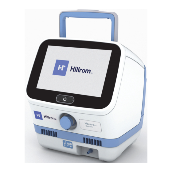
- Page 1 Volara System Instructions for Use Product No. PVL1 Baxter Hillrom is a part of Baxter...
- Page 3 PATENTS / PATENT hillrom.com/patents May be covered by one or more patents. See the Internet address above. The Hill-Rom companies are the proprietors of European, US, and other patents and pending patent applications. FOSS This product may contain software known as “free” or “open source” software (FOSS).
- Page 4 Bluetooth is a registered trademark of Bluetooth SIG, Inc. Baxter, Cough Pause, Hillrom, Maximus, Smart-Filter, Synclara, and Volara are trademarks of Baxter International, Inc. or its subsidiaries. Replace this manual (196654) if it is damaged and/or can not be read.
-
Page 5: Table Of Contents
Table of Contents Indications for Use ..........1 Patient Population. - Page 6 Table of Contents Adjust In-Therapy Settings in Automatic Mode... 34 Adjust the Cough Pause Settings ......36 Volara Therapy in Manual Mode .
- Page 7 Table of Contents Charge the Battery ........73 Pulse Oximeter .
- Page 8 Table of Contents Shipping and Packaging........97 Shipping for Repair.
-
Page 9: Indications For Use
INDICATIONS FOR USE The Volara System is intended for the mobilization of secretions, lung expansion therapy, the treatment and prevention of pulmonary atelectasis, and has the ability to provide supplemental oxygen when used with an oxygen supply. ATIENT OPULATION The Volara System is intended to deliver therapy to adults and children over the age of 2 in the acute care setting. -
Page 10: Important Information
Important Information IMPORTANT INFORMATION This section contains information about the Volara System: • Theory of operation (See page 2) • Contraindications (See page 3) It is important that you read and understand the information in this section before you use the system. HEORY OF PERATION The Volara System provides a therapy that enhances secretion... -
Page 11: Contraindications
Important Information ONTRAINDICATIONS CONTRAINDICATION: Contraindication—If patient conditions exist that cause the use of the system to be a risk to the patient, do not use the unit. Death or serious injury could occur. BSOLUTE ONTRAINDICATIONS The Volara System is contraindicated if this patient condition exists: •... -
Page 12: Symbols And Acronyms
Symbols and Acronyms SYMBOLS AND ACRONYMS OCUMENT YMBOLS This manual contains different typefaces and symbols to make the content easier to read and understand: • Standard text—used for regular data. • Boldface text—emphasizes a word or phrase and trademarks. • NOTE:—sets apart special data or important instruction clarification. - Page 13 Symbols and Acronyms Symbol Definition Rating for ingress protection in accordance with IEC 60259 Unique Device Identification information Unique Device Identification Type B equipment with an F-type applied part, according to EN 60601-1 Class II equipment (double insulated), according to EN60601-1 The Volara System conforms to the European Medical Devices Directive 93/42/EEC.
- Page 14 Symbols and Acronyms Symbol Definition Medical Device Identifies a replaceable fuse link in an electronic circuit Catalog number Non-sterile For multiple use on a single patient Physician prescription required Safe Working Load—includes the weight of control unit and accessories such as patient circuits Mass of the medical equipment Mass (in kilograms (kg)) of the medical equipment...
- Page 15 Symbols and Acronyms Symbol Definition Nebulizer port USB port On/off control Not made with natural rubber latex Temperature for transport and storage Relative humidity for transport and storage Atmospheric pressure for transport and storage Fragile This way up Keep Dry Stacking limit.
-
Page 16: Common Screen Symbols
Symbols and Acronyms OMMON CREEN YMBOLS These symbols may or may not be shown on the touchscreen. Symbol Description The system is connected to the AC power and not powered by the battery. The system is powered by the battery. The system is connected to a WiFi network. -
Page 17: Acronyms
Symbols and Acronyms CRONYMS Acronym Description CHFO Continuous High Frequency Oscillation CPEP Continuous Positive Expiratory Pressure Highest Programed Pressure Pressure Ceiling SpO2 Blood Oxygen Saturation Volara System Instructions for Use (196654 REV 8) -
Page 18: Safety Instructions
Safety Instructions SAFETY INSTRUCTIONS When using electrical products, especially when children are present, basic safety precautions should always be followed, including the following important safeguards. READ ALL INSTRUCTIONS BEFORE USING Training is provided by a Hill-Rom qualified trainer or respiratory therapist before the user uses the system for therapy delivery. - Page 19 Safety Instructions WARNING: (Warnings continued) Obey all warnings throughout the manual and also those below to help prevent injury and/or equipment damage: • Warning—Make sure the position of the control unit is such that you can quickly, without obstruction, disconnect the power cord from the power outlet on the wall, if required.
- Page 20 Safety Instructions WARNING: (Warnings continued) Obey all warnings throughout the manual and also those below to help prevent injury and/or equipment damage: • Warning—Do not allow any metallic conductive objects to contact the battery terminals. Do not short circuit a battery or throw it into the fire;...
- Page 21 Safety Instructions CAUTION: Obey all cautions throughout the manual and also those below to help prevent equipment damage: • Caution—Read this Instructions for Use before use. • Caution—Do not block the air openings of the system or place it on a soft surface, such as a bed or couch, where the air openings may be blocked.
-
Page 22: Features
Features FEATURES ONTROL Front Item Description Item Description Control unit Therapy port Touchscreen Nebulizer port On/off button Therapy port cap Volara System Instructions for Use (196654 REV 8) -
Page 23: Back
Features Back Item Description Item Description Handle Fuse holder Replaceable battery Air inlet filter (optional) Ventilation fan Nebulizer filter Power inlet Patient circuit holder USB port Volara System Instructions for Use (196654 REV 8) -
Page 24: Single Patient Use Circuit
Features IRCUIT ATIENT Item Description Item Description Smart-Filter Face mask (optional) Breathing hose Mouthpiece Handset Clear spontaneous breathing adapter Adapter, 22 mm x 22 mm K Oxygen bleed-in adapter (optional) Nebulizer kit Blue ventilator adapter (optional) Nebulizer tubing Handset plug (optional) Flexible tracheostomy In-line ventilator adapter, adapter (optional) -
Page 25: Assemble And Connect The Patient Circuit
Assemble and Connect the Patient Circuit ASSEMBLE AND CONNECT THE PATIENT CIRCUIT WARNING: To help prevent injury and/or equipment damage, obey these warnings: • Warning—Do not operate the system unless a Smart-Filter is attached to the system. • Warning—Do not use excessive force when assembling or disassembling the patient circuit. -
Page 26: Connect The Patient Circuit
Assemble and Connect the Patient Circuit ONNECT THE ATIENT IRCUIT WARNING: Warning—The patient circuit is for single patient use only. Always use a new patient circuit when using the system on a new patient. Failure to do so could cause cross contamination. NOTE: Make sure the Smart-Filter is always kept dry. - Page 27 Assemble and Connect the Patient Circuit Align the larger end of the Smart-Filter (B) with the therapy port on the control unit. Gently turn the Smart-Filter (B) to secure it to the therapy port. NOTE: Make sure the frosted part of the Smart- Filter covers the therapy port entirely.
- Page 28 Assemble and Connect the Patient Circuit • Face mask (J)— Insert and gently twist the adapter (I) into the output port of the clear spontaneous breathing adapter (G). Connect the other end of the adapter (I) to the face mask (J). NOTE: It may be difficult to connect the adapter to the face mask.
- Page 29 Assemble and Connect the Patient Circuit Connect the Patient Circuit to an Oxygen Source WARNING: To help prevent injury and/or equipment damage, obey these warnings: • Warning—Do not connect the system to an unregulated or high- pressure oxygen source. • Warning—The patient circuit is for single patient use only.
-
Page 30: Assemble The Nebulizer Kit And Add Medication
Assemble and Connect the Patient Circuit Assemble the Nebulizer Kit and Add Medication CAUTION: Caution—The fill volume of the nebulizer cup is 2 to 10 ml. Do not fill the cup outside of these limits. NOTE: A fill volume of 2.5 ml of medication is expected to last 10 minutes of nebulization. -
Page 31: Using A Bacterial Filter In-Line With The Volara System
Assemble and Connect the Patient Circuit Attach the other end of the nebulizer tubing to the base of the nebulizer cup. Connect the nebulizer lid attached with the cup to the nebulizer port of the clear spontaneous breathing adapter or blue ventilator adapter. If you are using a mouthpiece, face mask, or connecting the patient circuit directly to a tracheostomy tube—... -
Page 32: Set Up And Power On The Control Unit
Set Up and Power On the Control Unit SET UP AND POWER ON THE CONTROL UNIT CAUTION: Caution—Never block the air openings of the system or set it on a soft surface, such as a bed or couch, where the air openings may be blocked. Keep the air openings free of lint, hair, and the like. - Page 33 Set Up and Power On the Control Unit • Battery power— Turn the patient circuit holder aside to get access to the battery compartment. Remove the battery cover (if installed). Insert the right side of the battery (with LED indicator) into the battery compartment first.
-
Page 34: Power Off The Control Unit And Store The System
Power Off the Control Unit and Store the System POWER OFF THE CONTROL UNIT AND STORE THE SYSTEM When the therapy is complete, do these steps: Press and hold the On/Off button for at least 5 seconds. • If the system is operating on AC power, the system enters into sleep mode. -
Page 35: Volara Therapy
Volara Therapy VOLARA THERAPY BOUT THE Item Description Automatic therapy mode Manual therapy mode Volara System Instructions for Use (196654 REV 8) -
Page 36: About The Options Menu
Volara Therapy BOUT THE PTIONS Option Description Home—Go to the Home menu. Care Plan—Access the preset therapy settings. Device Settings—Access the device control settings, enable clinical access, retrieve logs, and configure connections to accessories. Help—See information to guide you in using the system. -
Page 37: Start A Therapy
Volara Therapy TART A HERAPY NOTES: • Always use the settings prescribed by the physician. • Avoid operating the touchscreen with wet fingers as this will reduce the screen response time. • For home use, the maximum pressure setting is 50 cmH2O. Volara therapy is available in both automatic and manual modes. - Page 38 Volara Therapy sure that the patient maintains a tight seal on the mouthpiece during the therapy. • Flexible tracheostomy adapter—if the patient has a tracheostomy tube or endotracheal tube, use the flexible tracheostomy adapter to connect the tracheal tube to the system.
-
Page 39: Volara Therapy In Automatic Mode
Volara Therapy OLARA HERAPY IN UTOMATIC Basic View in Automatic Mode Item Description Item Description Name of the preset Options tab therapy selected Digital manometer Remaining therapy time Therapy status Current stage of total stages set in the preset therapy Heart rate and pulse In-Therapy edit control oximeter readings... -
Page 40: Start A Therapy In Automatic Mode
Volara Therapy Start a Therapy in Automatic Mode NOTE: Before you start a therapy, make sure you have connected the applicable patient circuit to the system. See “Connect the Patient Circuit” on page 18. Press Automatic. • When prompted, scan the patient’s ID barcode with the paired barcode reader. - Page 41 Volara Therapy • During the therapy, you can pause or stop a therapy. Or, press Resume to continue a paused therapy session. NOTE: If a therapy is paused for more than 5 minutes, the therapy stops and a warning message shows. Follow the on-screen instructions. When the therapy is stopped or complete, the therapy summary shows.
-
Page 42: Adjust In-Therapy Settings In Automatic Mode
Volara Therapy Adjust In-Therapy Settings in Automatic Mode NOTE: Available only if Clinical Access is enabled. See page 53. When a therapy is in progress, you can use the In-Therapy Edit control to adjust these therapy settings— • pressure • frequency (in CHFO stage) •... - Page 43 Volara Therapy • If required, press Low, Med, or High to toggle between different intensities of frequency during the therapy. Press Done to go to the therapy screen. Press Apply to All to apply the new settings to all the remaining CPEP or CHFO stages in the therapy.
-
Page 44: Adjust The Cough Pause Settings
Volara Therapy Adjust the Cough Pause Settings NOTE: Applicable only to preset therapy plans. Press Automatic. • When prompted, scan the patient’s ID barcode with the paired barcode reader. For pairing instructions, see page 56. Before you start the therapy, swipe the Options tab left, and press Care Plan. -
Page 45: Volara Therapy In Manual Mode
Volara Therapy OLARA HERAPY IN ANUAL WARNING: Warning—Due to the complexity of the device, the manual mode is locked by default and only intended for advanced users who demonstrate device competency after receiving clinical training. NOTE: Only advanced users with the Clinical Access key code can unlock the manual mode. -
Page 46: Start A Therapy In Manual Mode
Volara Therapy Start a Therapy in Manual Mode NOTE: Before you start a therapy, make sure you have connected the applicable patient circuit to the system. See “Connect the Patient Circuit” on page 18. Press Manual. • When prompted, scan the patient’s ID barcode with the paired barcode reader. - Page 47 Volara Therapy • If required, press the CHFO Freq. control and select the preferred frequency. GUI Map Pg 49 BM1.11 • If a nebulizer is used, press the nebulizer icon to enable therapy with a nebulizer. The nebulizer icon lights up. Place the patient interface in position on the patient.
- Page 48 Volara Therapy When the therapy is complete, press Stop. The therapy summary shows. Note the number of treatment sessions completed with the connected patient circuit. Number of times the patient circuit has been used Maximum number of times the patient circuit can be used Press Back to go back to the manual therapy screen.
-
Page 49: Volara Therapy With An In-Line Ventilator
Volara Therapy OLARA HERAPY WITH AN ENTILATOR LINE WARNING: Obey these warnings to help prevent patient injury and/or equipment damage: • Warning—Only persons trained to use the Volara System and ventilators should provide therapy to ventilated patients. • Warning—Do not deliver any other modes of therapy except CHFO during in-line use with a ventilator. - Page 50 Volara Therapy Connect a spring-valve “tee” adapter (N—patient’s own) into the inspiratory limb of the ventilator breathing circuit. Start the therapy. See “Volara Therapy in Automatic Mode” on page 31 or “Volara Therapy in Manual Mode” on page 37. Connect the other end of the in-line ventilator adapter to the port of the spring-valve “tee”...
-
Page 51: Advanced Volara Therapy Settings
Volara Therapy DVANCED OLARA HERAPY ETTINGS These settings allow you to create, modify, rename, and delete a preset therapy. Create a New Preset Therapy Plan NOTE: Available only if Clinical Access is enabled. See page 53. Press Automatic. Swipe the Options tab left, and press Care Plan. - Page 52 Volara Therapy Press the down arrow and select the preferred option: • CPEP—Set the therapy pressure, therapy duration, and enable or disable the use of a nebulizer. • CHFO—Set the therapy pressure, therapy duration, frequency of continuous high frequency pressure, and enable or disable the use of a nebulizer.
- Page 53 Volara Therapy NOTE: The maximum pressure that can be set depends on the pressure ceiling limit defined in the Pressure Management settings. See page 54. Press Save to save the changes. Or, press Cancel. To add more stages, do Step 4 to Step 8. 10.
-
Page 54: Modify A Preset Therapy Plan
Volara Therapy 13. Select the new preset therapy, and press Start. The therapy starts. Modify a Preset Therapy Plan Press Automatic. Swipe the Options tab left, and press Care Plan. Select a preset therapy plan to modify. Press Edit. When prompted, press Modify. Swipe right or left to select the stage to modify. - Page 55 Volara Therapy • CHFO—Modify the therapy pressure, therapy duration, frequency of continuous high frequency pressure, and enable or disable the use of a nebulizer. • NEB—Enable or disable the therapy with the use of a nebulizer and/or adjust the duration of use with a nebulizer.
- Page 56 Volara Therapy • To turn Cough Pause on or off, press Options and slide the setting to ON or OFF. • If Cough Pause is enabled, select the setting to adjust the interval and duration of the cough pause. Use the + or – control to adjust the setting.
-
Page 57: Rename A Preset Therapy Plan
Volara Therapy Rename a Preset Therapy Plan Select the preset therapy plan to rename. Press and hold the therapy plan until the on-screen keyboard shows. Use the on-screen keyboard to enter any 5 alphanumeric characters for the new name. Press Enter when complete. Or, press Cancel. -
Page 58: Delete A Preset Therapy Plan
Volara Therapy Delete a Preset Therapy Plan NOTE: Available only if Clinical Access is enabled. See page 53. Press Automatic. Swipe the Options tab left, and press Care Plan. Select the preset therapy plan to delete. Press Edit. When prompted, press Delete. Press Proceed to delete the plan. -
Page 59: Device Settings
Device Settings DEVICE SETTINGS Swipe the Options tab left, and press Device Settings. In Device Settings, you can— • Adjust the screen brightness • Adjust the date and time • Change the system menu language • Enable or disable Clinical Access •... -
Page 60: Adjust The Date And Time Settings
Device Settings DJUST THE ATE AND IME SETTINGS Press Device, and press Date-Time. Move the slider to select the preferred setting for each item. To change the time zone, press Modify. Scroll up or down to select the correct time zone, and press Save. When complete, press Home to exit. -
Page 61: Enable Or Disable Clinical Access
Device Settings NABLE OR ISABLE LINICAL CCESS Clinical Access allows facility-authorized persons to access and set up these features: • Set the maximum pressure ceiling setting available to the user • Modify preset therapy settings • Import and export device settings •... -
Page 62: Enable Or Disable Manual Mode Access
Device Settings NABLE OR ISABLE ANUAL CCESS WARNING: Warning—Due to the complexity of the device, the manual mode is locked by default and only intended for advanced users who demonstrate device competency after receiving clinical training. NOTE: Available only if Clinical Access is enabled. See page 53. Press Device, and press Controls. -
Page 63: Set The Pressure Ceiling Limit (Pressure Management)
Device Settings ET THE RESSURE EILING IMIT RESSURE ANAGEMENT The Pressure Management feature allows facility-authorized persons to control the maximum pressure selection by setting a pressure ceiling limit. The user is prevented from setting a therapy pressure that exceeds the limit defined in the device settings. -
Page 64: Connect A Barcode Reader Or Pulse Oximeter
Device Settings Press the + or - controls to select the required PC setting. NOTES: • Each press of the control increases/decreases the PC setting by five (5) units. • The PC ranges between 5 to 70 cmH2O and is limited to the HPP gathered from the system. - Page 65 Device Settings Press Connect. Slide the setting for Bluetooth to ON. Press SpO to add a pulse oximeter or Barcode to add a barcode reader. • To automatically detect and pair the Bluetooth device nearby, press Scan. A list of devices shows. •...
-
Page 66: Connect To A Wifi Network (Available Only In The Us)
Device Settings ONNECT TO A ETWORK VAILABLE NLY IN THE This feature is only available on systems ordered with WiFi capability. NOTES: • After the first time connection, the WiFi will automatically connect when the Volara System is turned on and within the range of the WiFi network. -
Page 67: Connect To A Public Network
Device Settings Select the network to join. Use the on-screen keyboard to enter the network Password. To confirm the entry, press Enter. Or, press Cancel. When the connection is successful, a green check mark shows next to the access point name. •... - Page 68 Device Settings Press Connect. Press WiFi, and slide the setting to ON. Press to locate the wireless Scan networks available. Depending on the number of networks available, the scan may take a few minutes. When complete, a list of wireless networks shows. When the connection is successful, a green check mark shows next to the access point name.
-
Page 69: Connect To An Enterprise Network
Device Settings Connect to an Enterprise Network Swipe the Options tab left, and press Device Settings. Press Connect. Press WiFi, and slide the setting to ON. Press to search for wireless Scan networks available. Depending on the number of networks available, the scan may take a few minutes. -
Page 70: Configure The Network Settings
Device Settings • If the connection is unsuccessful, an error message shows. Press Return to go to the previous screens and make your entries again. Press Home to exit. Configure the Network Settings After the Volara System is connected to the WiFi network, press Settings. -
Page 71: Test The Connection To Electronic Medical Records (Emr)
Device Settings Slide WiFi to OFF and back to ON again to reset the WiFi connection. The network settings are applied. Press Home to exit. Test the Connection to Electronic Medical Records (EMR) If you have an EMR account assigned by the medical facility, you can submit the therapy data from the Volara System to update your EMR. -
Page 72: Retrieve Logs
Device Settings Select each field and use the on-screen keypad to enter the settings for: • Server IP • Port Number • NTP IP After all entries are made, press on the yellow highlighted field to close the keypad. To test the entries made, press Test Connection. -
Page 73: Retrieve The Therapy Logs
Device Settings Retrieve the Therapy Logs Swipe the Options tab left, and press Device Settings. Select Data. NOTE: Not all options are available at the same time. To view the Therapy Log, select Review. A list of therapy sessions shows. Select the date and time of the session on the left hand panel. -
Page 74: Retrieve The Error Log
Device Settings Retrieve the Error Log Swipe the Options tab left, and press Device Settings. Select Data. NOTE: Not all options are available at the same time. To view the Error Log, select Review. A list of errors shows. Select the date and time of the session on the left hand panel. -
Page 75: Import And Export Device Settings
Device Settings MPORT AND XPORT EVICE ETTINGS You can export the settings from one system and import the settings into another system. NOTES: • Before you start, format the USB drive to FAT16 or FAT32 format on your computer. This action deletes all information currently stored on the USB drive. -
Page 76: View The Firmware Version And System Information
Device Settings NOTE: To prevent unauthorized persons from adjusting the settings, disable Clinical Access after you have adjusted the settings. Press Device, and press Controls. Slide Clinical Access to OFF. IEW THE IRMWARE ERSION AND YSTEM NFORMATION Swipe the Options tab left, and press Device Settings. -
Page 77: Accessories
Accessories ACCESSORIES Item Part Number Replaceable Battery 194566S See page 70. Pulse Oximeter, Bluetooth 196694 See page 74. WiFi Module, USB 198658 Pole Clamp Assembly M08235 See page 75. Stand and Cart Assembly M08177 (with Pole Clamp) See page 75. Carrying Case 209558 Volara System Instructions for Use (196654 REV 8) -
Page 78: Replaceable Battery
Accessories EPLACEABLE ATTERY Use only the Hill-Rom approved battery (194566S). The Volara System can be powered by a Lithium-ion battery when AC power is not available. A fully charged new battery can support 6 sessions of a typical Volara therapy. WARNING: Obey these warnings to help prevent patient injury and/or equipment damage:... -
Page 79: Install The Battery
Accessories Install the Battery Turn the patient circuit holder aside to get access to the battery compartment. Remove the battery cover (if installed). Insert the right side of the battery (with LED indicator) into the battery compartment first. Insert the left side of the battery until the battery locks into position. - Page 80 Accessories When the replaceable battery is installed in the control unit, the battery symbol shows on the touchscreen. The battery symbol shows the battery status: Symbol Battery Status The battery charge is low. The battery is charging. The battery is 25% charged. The battery is 50% charged.
-
Page 81: Charge The Battery
Accessories You can also check the battery charge at the battery. To do so, press the button next to the LED indicator. LED indicator Battery Status Four green bars The battery is fully charged. Blinking bars The battery charge is low. Blinking bars when the control The battery is charging. -
Page 82: Pulse Oximeter
Accessories ULSE XIMETER NOTE: Use only the Hill-Rom approved pulse oximeter (196694). The pulse oximeter is connected to the Volara System by Bluetooth. The pulse oximeter monitors the patient’s blood oxygen level and heart rate (pulse). When the pulse oximeter is connected, you can view the readings on the control unit touchscreen. -
Page 83: Mobile Stand And Pole Clamp Assembly
Accessories OBILE TAND AND LAMP SSEMBLY NOTE: Use only the Hill-Rom approved mobile stand and pole clamp assembly (M08177). Install the Stand Lock the casters to prevent the stand base from moving. Install the pole with cart into the stand base. Lay the stand base on its side. - Page 84 Accessories Install the top pole into the stand base. Make sure the groove is aligned with its opening on the bottom pole. Use the hex wrench to tighten the pole connection. Volara System Instructions for Use (196654 REV 8)
-
Page 85: Install The Tray And Pole Clamp
Accessories Install the Tray and Pole Clamp Note the guide on the back of the tray. Turn the tray over, and attach the pole clamp to the tray with the supplied parts from the kit. Volara System Instructions for Use (196654 REV 8) -
Page 86: Install The Control Unit On The Cart And Stand Assembly
Accessories Install the Control Unit on the Cart and Stand Assembly Find the preferred position to install the tray. Turn the knob on the pole clamp clockwise to hold the tray in position on the cart. Put the control unit on the tray. Make sure the screw holes on the bottom of the control unit are aligned with the screw holes on the tray. -
Page 87: Move The Stand
Accessories Move the Stand CAUTION: Obey these cautions to help prevent equipment damage: • Caution—Do not apply force or pull the control unit when it is connected to the oxygen source. • Caution—Do not pull the control unit using the breathing hose or circuit tubing during transportation. - Page 88 Accessories Volara System Instructions for Use (196654 REV 8)
-
Page 89: Replacement Parts And Kits
Replacement Parts and Kits REPLACEMENT PARTS AND KITS ONTROL ARTS Description Part number Battery compartment cover 194779 Foam kit, air inlet filter 203923S Foam kit, nebulizer filter 202909S Fuse, 4 A 250 V 207914 Patient circuit hook kit 203042S Therapy port cap 196680 Power Cord, 3 m (10') 181995... -
Page 90: Cleaning And Disinfecting
Cleaning and Disinfecting CLEANING AND DISINFECTING CAUTION: Caution—Use only Environmental Protection Agency (EPA) registered chemicals for the cleaning or disinfection of the Volara System (US only). LEAN THE ONTROL NIT AND TAND WARNING: Warning—Failure to disconnect the unit from its power source during cleaning could cause injury or equipment damage. -
Page 91: Use
Cleaning and Disinfecting Compatible Cleaning and Disinfecting Solutions Contact Chemical Class Active Ingredient Time Phenolic Ortho-Phenylphenol 10 min Ortho-Benzyl-para-Chlorophenol Alcohol Isopropyl alcohol 5 min Quaternary Didecyl dimethyl ammonium 10 min ammonium chloride chloride Alkyl dimethyl benzyl ammonium chloride Alcohol/ Diisobutylphenoxyethoxyethyl 3 min Quaternary Dimethyl Benzyl Ammonium... -
Page 92: Clean The Single Patient Use Circuit-Home Use
Cleaning and Disinfecting —H LEAN THE INGLE ATIENT IRCUIT WARNING: To help prevent patient infection and/or equipment damage, obey these warnings and cleaning instructions: • Warning—If the Smart-Filter is damaged, visibly soiled or wet, replace it. For typical examples of soiled and damaged Smart-Filter, see page 85. - Page 93 Cleaning and Disinfecting Examples of Typical Damage of the Smart-Filter Each of these pictures show examples of possible damage. These pictures do not show all possible types of damage. Soiled Filter Mucus or liquid is attached to the membrane. Damaged Filter External casing of the filter has cracks or pieces missing.
-
Page 94: Clean The Nebulizer Kit
Cleaning and Disinfecting LEAN THE EBULIZER NOTE: Do not put the nebulizer tubing in water. Disconnect the nebulizer tubing from the medicine cup. Remove the lid from the medicine cup. Discard any unused medication in accordance with facility protocol or the medication instructions. -
Page 95: Maintenance
Maintenance MAINTENANCE WARNING: Warning—To prevent injury and/or equipment damage, do not do maintenance when the system is in use. NLET ILTER Examine the inlet filter every month, and clean it as necessary. Replace the inlet filter every twelve (12) months. To clean the filter, do as follows: Power off the control unit. -
Page 96: Nebulizer Filter
Maintenance EBULIZER ILTER Examine the nebulizer filter every month, and clean it as necessary. Replace the nebulizer filter every twelve (12) months. To clean the filter, do as follows: Power off the control unit. Remove the nebulizer filter from the back of the control unit. NOTE: If the filter is damaged, replace it. -
Page 97: Automatic Firmware Update (Available Only In The Us)
Maintenance UTOMATIC IRMWARE PDATE VAILABLE NLY IN THE When a new firmware is available, the package is automatically downloaded to your Volara System. You will be prompted to start the installation. Before you continue, note the amount of time required to complete the firmware installation. -
Page 98: Expected Life
Expected Life EXPECTED LIFE The expected service life for the control unit is five years from its date of purchase. The expected service life of the single patient use circuit is 30 days of treatment or 90 treatment sessions. The expected service life of the battery is one year from its date of purchase. -
Page 99: Troubleshooting
Troubleshooting TROUBLESHOOTING WARNING: Warning—Only authorized persons should service the Volara System. Service by unauthorized persons could cause personal injury or equipment damage. Do not modify this system without the authorization of the manufacturer. ONTROL OWER If the control unit is powered by AC power: •... -
Page 100: Information Indicators
Troubleshooting NFORMATION NDICATORS Audible indicators and visual indicators lets you know that attention is needed at the system. Audio Alerts Beeps provide audible indications of the status of the system. Alert Pattern Status Three beeps Attention is needed at the system. Check the touchscreen for more information. -
Page 101: Caution Messages
Troubleshooting Error Code Do this: Make sure only the Hill-Rom approved battery (194566S) is used. Press Return after reading the on-screen message. Make sure the battery is correctly installed in the control unit. If necessary, remove the battery and install it. See “Install the Battery” on page 71. - Page 102 Troubleshooting Error Code Do this: 015, 016, 017, 018 Press Return after you read the on-screen message. Power off the control unit and let it cool down for at least 5 minutes. Power on the control unit. If the same message shows, power off the control unit and let it cool down for at least 30 minutes.
- Page 103 Troubleshooting Error Code Do this: Make sure a tight seal is maintained on the face mask or mouthpiece. Examine the connections between the patient circuit components, tubings, and the control unit for any source of leaks. If necessary, disassemble the patient circuit and assemble it again.
-
Page 104: Storage And Handling
Storage and Handling NOTE: In most instances, you may have to restart the system. If the problem continues, contact Hill-Rom: • In the USA, call Hill-Rom at 800-426-4224. • Outside of the USA, contact your distributor or local Hill-Rom representative, or go to respiratorycare.hill-rom.com. STORAGE AND HANDLING To store or transport the Volara System, do these steps: Put the therapy port cap over the therapy port. -
Page 105: Shipping And Packaging
Storage and Handling HIPPING AND ACKAGING WARNING: To help prevent injury and/or equipment damage, obey these warnings: • Warning—Do not ship the battery with over a 30% charge. • Warning—Do not store the battery at temperatures above 140°F (60°C), such as inside a car on a hot day or in direct sunlight. CAUTION: Caution—If shipping is required, the original packing material provides the best protection for the system. -
Page 106: Specifications
Specifications SPECIFICATIONS RODUCT DENTIFICATION Product Number Description PVL1 Volara System PECIFICATIONS RODUCT Feature Description CPEP 5 to 25 cmH2O CHFO 5 to 70 cmH2O Nebulizer 5 cmH2O CPEP/Nebulizer duration 1 sec to 5 minutes CHFO duration 1 sec to 10 minutes CHFO frequencies Low, medium, and high Pressure accuracy... -
Page 107: Power Requirements
Specifications OWER EQUIREMENTS Condition Range Line voltage 100 - 240 V AC Supply frequency 50 - 60 Hz Supply current 2.0 - 1.0 A Mode of operation Non-continuous: 5 minutes ON or 20 minutes OFF at CHFO pressure setting of 65 cmH2O and above Fuse rating Fuse, 4 A H 250 V Replaceable Battery (Optional) -
Page 108: System Cool Down
Specifications YSTEM CAUTION: Caution—Failure to follow the system cool down guidelines below could cause equipment damage. Condition Cool Down Period System operates continuously for At least 20 minutes 5 minutes, at CHFO pressure setting of 65 cmH2O and above IRELESS OMMUNICATION Bluetooth The Volara System, Model PVL1 features Bluetooth connectivity. -
Page 109: Wifi (Optional)
Specifications WiFi (Optional) For users in the US, the Volara System also features a WiFi module to export system and therapy data in both acute care and home care environments. Feature Dimension WLAN IEEE 802.11a, 802.11b, 802.11g, 802.11n Frequency 2412 MHz - 2462 MHz 5180 MHz - 5240 MHz 5745 MHz - 5825 MHz Transmit power (+/- 2 dBm) -
Page 110: Essential Performance
Specifications Type of Standard Standards FCC Part 15 Subpart B EN 301 489-1 EN 301 489-17 EN 60601-1-2 IEC 60601-1-2 IEEE C63.27 RTCA DO-160G Sections 20 and 21 Radio FCC Part 15 Subpart C (2.4 GHz) FCC Part 15 Subpart E (5.0 GHz) ETSI EN 300 330 Bio-compatibility ISO 10993-1... - Page 111 Specifications Part 15B compliance statements for digital devices: NOTE: This equipment has been tested and found to comply with the limits for a Class B digital device, pursuant to part 15 of the FCC Rules. These limits are designed to provide reasonable protection against harmful interference in a residential installation.
-
Page 112: Electromagnetic Compatibility Guidance
Specifications LECTROMAGNETIC OMPATIBILITY UIDANCE The Volara System is suitable for the electromagnetic environment of typical home, commercial, or hospital settings. WARNING: To help prevent injury and/or equipment damage, obey these warnings: • Warning—Portable RF communications equipment (including peripherals such as antenna cables and external antennas) should be used no closer than 30 cm (12") to any part of the Volara System, including cables specified by the manufacturer. - Page 113 Specifications Guidance and Manufacturer's Declaration—Electromagnetic Emissions The Volara System is intended for use in the electromagnetic environment specified below. The customer or the user of the Volara System should make sure that it is used in such an environment. Emissions Test Compliance Electromagnetic Environment—Guidance RF Emissions...
- Page 114 Specifications Guidance and Manufacturer's Declaration—Electromagnetic Immunity The Volara System is intended for use in the electromagnetic environment specified below. The customer or the user of the Volara System should make sure that it is used in such an environment. IEC 60601 Compliance Electromagnetic Environment—...
- Page 115 Specifications Electromagnetic Immunity to Wireless Communications The Volara System delivered therapy normally when tested for immunity at these set- tings: Frequency (MHz) Test Severity Level 27 V/m, 50% PM 18 Hz 28 V/m, FM ± 5 kHz,1 kHz 9 V/m, 50% PM 217 Hz 9 V/m, 50% PM 217 Hz 9 V/m, 50% PM 217 Hz 28 V/m, 50% PM 18 Hz...
-
Page 116: Nebulizer Performance
Nebulizer Performance NEBULIZER PERFORMANCE The following specifications were established through performance tests using an eight-stage cascade impactor at a flow rate of 12 liters per minute (L/min) and 28 L/min equipped with a USP <601> induction port throat. Three sample points per drug were collected. Aerosol was sampled directly from the outlet. -
Page 117: Chfo Mode
Nebulizer Performance CHFO M Parameter Drug 28 L/min 12 L/Min Mass median Albuterol Sulfate (2.5 mg/3 ml) 1.33 μm +/- 1.33 μm +/- 0.06 aerodynamic 0.06 diameter (MMAD) Ipratropium bromide 1.33 μm +/- 1.33 μm +/- 0.06 (0.5 mg / 2.5 mL) 0.06 Cromolyn Sodium 1.33 μm +/-... -
Page 118: Cpep Mode
Nebulizer Performance CPEP M Parameter Drug 28 L/min 12 L/Min Mass median Albuterol Sulfate (2.5 mg/3 ml) 1.27 μm +/- 0.06 1.33 μm +/- 0.06 aerodynamic Ipratropium bromide 1.33 μm +/- 0.06 1.33 μm +/- 0.06 diameter (0.5 mg / 2.5 mL) (MMAD) Cromolyn Sodium 1.30 μm +/- 0.00... -
Page 119: Aerosol Mode
Nebulizer Performance EROSOL Parameter Drug 28 L/min 12 L/Min Mass median Albuterol Sulfate (2.5 mg/3 ml) 1.37 μm +/- 0.06 1.83 μm +/- 0.21 aerodynamic Ipratropium bromide 1.33 μm +/- 0.06 1.93 μm +/- 0.06 diameter (0.5 mg / 2.5 mL) (MMAD) Cromolyn Sodium 1.33 μm +/- 0.06... - Page 120 Nebulizer Performance NOTES: Volara System Instructions for Use (196654 REV 8)
Need help?
Do you have a question about the Hillrom Volara PVL1 and is the answer not in the manual?
Questions and answers
my patient has excessive oral secretions that requires frequent suctioning because she cannot swallow her secretions, is volara safe to use