Table of Contents
Advertisement
Quick Links
Advertisement
Table of Contents

Related Manuals for Innova 5300LaT


Summary of Contents for Innova 5300LaT
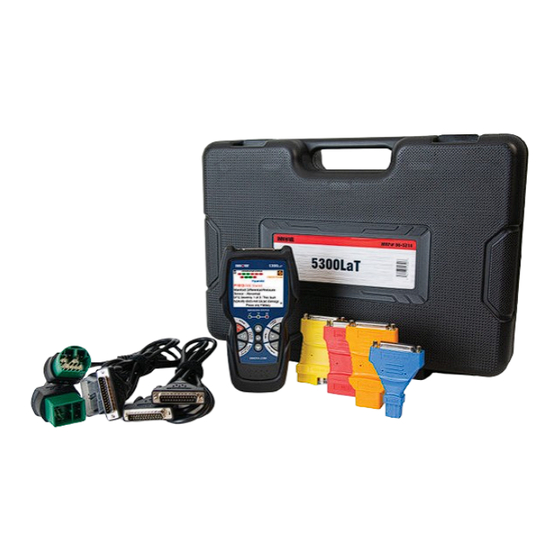
- Page 1 OBD2&1 Diagnostic Tool Kit...
- Page 2 WELCOME TO THE INNOVA FAMILY! Hello... On behalf of everyone at INNOVA, we want to assure you that we are committed to assisting you and your customers with routine vehicle maintenance tasks. We take pride in offering simple-to- use and easy-to-understand diagnostic solutions. Here are some of the things you can do with the INNOVA®...
-
Page 3: Table Of Contents
TABLE OF CONTENTS LEGAL INFORMATION � � � � � � � � � � � � � � � � � � � � � � � � � � � � � � � � � �1 SAFETY PRECAUTIONS � � � � � � � � � � � � � � � � � � � � � � � � � � � � � � � � 3 INTRODUCTION �... - Page 4 TABLE OF CONTENTS For Mercedes-Benz: ..........31 For Nissan: .
- Page 5 TABLE OF CONTENTS Viewing Data Stored in Memory � � � � � � � � � � � � � � � � � � � � � � � � � � � � � � � � � � � � � � � � � � � � 50 OBD1 DIAGNOSTICS �...
-
Page 6: Legal Information
Licensee and End Users acknowledge such ownership, confidential information, and intellectual property rights and will not take any action to jeopardize, limit or interfere in any manner with Innova’s or its licensors’ or other suppliers’ ownership of or rights with respect to the Products and Services. The Products and Services may be protected by Patent, Trademark, Copyright and/or other intellectual property laws and by international treaties. - Page 7 LEGAL INFORMATION Patents PATENTS Innova Electronics Corp. protects its intellectual property with numerous U.S. patents, which were used to research, design and manufacture this product. Please visit https://www.innova.com/pages/patents for additional information. FIRMWARE VERSION Please note that the images and functions on this manual may differ based on the current Firmware Version (FW) you have.
-
Page 8: Safety Precautions
SAFETY PRECAUTIONS Safety First! SAFETY PRECAUTIONS SAFETY FIRST! It is important that every user utilizing this product read all instructions and warnings included within this manual to ensure your safety, the safety of others, and to prevent damage to this product & vehicles being diagnosed and repaired. - Page 9 SAFETY PRECAUTIONS Safety Alert Icons SAFETY ALERT ICONS As you read this manual, color-coded icons are used throughout to identify safety alerts and warnings. These are provided to help prevent serious injury to you, injury to bystanders, and damage to property or equipment. They are characterized as follows: Yellow Icon –...
-
Page 10: Introduction
INTRODUCTION Scan Tool Controls and Indicators INTRODUCTION SCAN TOOL CONTROLS AND INDICATORS See Figure 1 for the locations of items 1 through 14, below. Display – Color LCD display shows menus and submenus, test results, Scan Tool functions and Monitor status information. -
Page 11: Scan Tool Display Functions
INTRODUCTION Scan Tool Display Functions Menu. 13. LD button – When pressed while linked to a vehicle, places the Scan Tool in Live Data mode. 14. OBD II Cable (detachable) – Connects the scan tool to the vehicle's Data Link Connector (DLC) when retrieving codes from OBD II systems. -
Page 12: Initial Setup
INTRODUCTION Initial Setup Scan Tool Internal Battery icon – When visible, indicates the Scan Tool batteries are “low” and should be replaced. If the batteries are not replaced when the battery icon is “on”, all 3 LEDs will light to warn that the batteries need replacement. -
Page 13: Scan Tool Battery Replacement
INTRODUCTION Scan Tool Battery Replacement NOTE: After the initial language and unit of measurement selections are performed, these, as well as other settings, can be changed as desired under the Tool Settings section. [See page SCAN TOOL BATTERY REPLACEMENT Replace batteries when the battery symbol is visible on the display and/or the screen displays a warning message: “Batteries are low. -
Page 14: Using The Scan Tool
USING THE SCAN TOOL Retrieving OBD2 Diagnostic Trouble Codes USING THE SCAN TOOL RETRIEVING OBD2 DIAGNOSTIC TROUBLE CODES Never replace a part based only on the DTC definition. Each DTC has a set of testing procedures, instructions, and flow charts that must be followed to confirm the location of the problem. Always refer to the vehicle's service manual for detailed testing instructions. - Page 15 USING THE SCAN TOOL Retrieving OBD2 Diagnostic Trouble Codes NOTE: A PROTOCOL is a set of rules and procedures for regulating data transmission between computers, and between testing equipment and computers. As of this writing, five different types of protocols (ISO 9141, Keyword 2000, J1850 PWM, J1850 VPW and CAN) are in use by vehicle manufacturers.
- Page 16 USING THE SCAN TOOL Retrieving OBD2 Diagnostic Trouble Codes 11. Read and interpret Diagnostic Trouble Codes/system condition using the display and the green, yellow, and red LEDs. NOTE: The green, yellow, and red LEDs are used (with the display) as visual aids to make it easier to determine engine system conditions.
-
Page 17: The Main Menu
USING THE SCAN TOOL The Main Menu is also saved in the vehicle’s computer memory. The record saved is called Freeze Frame data. Saved engine conditions include, but are not limited to: engine speed, open or closed loop operation, fuel system commands, coolant temperature, calculated load value, fuel pressure, vehicle speed, air flow rate, and intake manifold pressure. -
Page 18: The System Menu - Oem Functions
USING THE SCAN TOOL The System Menu – OEM Functions Service Reset – Lets you reset the Oil Maintenance Light [See page 29] and reset the Battery Monitor System after battery replacement [See page 30]. Service Check – Lets you view the current engine oil level, oil life remaining and brake pad life. [See page Firmware Version –... -
Page 19: Viewing Oem Enhanced Dtcs (Ford/Mazda Only)
USING THE SCAN TOOL Viewing OEM Enhanced DTCs (Ford/Mazda Only) ━ Ensure your vehicle is OBD2 compliant. Verify the connection at the DLC, and verify the ignition is ON. ━ Turn the ignition OFF, wait 5 seconds, then back ON to reset the computer. ━... - Page 20 USING THE SCAN TOOL Viewing OEM Enhanced DTCs (Ford/Mazda Only) DTCs for either the “Continuous Memory DTCs”, “KOEO (Key On Engine Off) Test” or “KOER (Key On Engine Running) Test.” Select the desired option, then press ENTER If KOER is selected, an advisory message shows. Start and warm the engine to normal operating temperature, then ━...
-
Page 21: Viewing Abs Dtcs
USING THE SCAN TOOL Viewing ABS DTCs NOTE: I/M MONITOR STATUS icons are not displayed when viewing enhanced DTCs. NOTE: In the case of long code definitions, a small arrow is shown in the upper/ lower right-hand corner of the code display area to indicate the presence of additional information. -
Page 22: Erasing Diagnostic Trouble Codes (Dtcs)
USING THE SCAN TOOL Erasing Diagnostic Trouble Codes (DTCs) NOTE: I/M MONITOR STATUS icons are not displayed when viewing ABS DTCs. NOTE: In the case of long code definitions, a small arrow is shown in the upper/ lower right-hand corner of the code display area to indicate the presence of additional information. - Page 23 USING THE SCAN TOOL Erasing Diagnostic Trouble Codes (DTCs) Press and release ERASE . A confirmation message shows. If you are sure you want to proceed, choose Yes to continue. If you do not want to proceed, choose No to cancel the erase procedure. If you chose to erase DTCs, a “One moment please…”...
-
Page 24: Live Data Mode
LIVE DATA MODE Viewing Live Data LIVE DATA MODE The Scan Tool lets you view and/or record "real-time" Live Data. This information includes values (volts, rpm, temperature, speed etc.) and system status information (open loop, closed loop, fuel system status, etc.) generated by the various vehicle sensors, switches, and actuators. -
Page 25: Customizing Live Data (Pids)
LIVE DATA MODE Customizing Live Data (PIDs) a small arrow is shown on the display. Press UP and DOWN , as necessary, to view all available PID data. If communication with the vehicle is lost while viewing Live Data, an advisory message displays. Press and release ENTER to view the currently selected PID in “graph”mode. -
Page 26: Recording (Capturing) Live Data
LIVE DATA MODE Recording (Capturing) Live Data If custom Live Data was not previously selected, the Custom Live Data menu displays. Proceed to step 3. Press UP and DOWN to scroll through the available PIDs. When the PID you wish to display is highlighted, press ENTER (a “checkmark”... - Page 27 LIVE DATA MODE Recording (Capturing) Live Data If the Scan Tool fails to establish communication with the vehicle, a “Communication Error” message displays. Ensure your vehicle is OBD2 compliant. ━ ━ Verify the connection at the DLC, and verify the ignition is ON. Turn the ignition OFF, wait 5 seconds, then back ON to reset the computer.
-
Page 28: Record By Manual Trigger
LIVE DATA MODE Recording (Capturing) Live Data Yes and press ENTER to playback Live Data [See page 24] or select No and press to return to the Live Data menu, as desired. ENTER If recording was not successful, an advisory message shows on the display. Press the ENTER button to return to the Record Live Data menu. -
Page 29: Live Data Playback
LIVE DATA MODE Live Data Playback When the problem occurs, press and release LD. A progress message shows on the display. You can stop and save recorded Live Data at any time by pressing ENTER ━ When recording is complete, a confirmation screen displays. Select Yes and press ENTER to playback Live Data [See page 24] or select No and press ENTER... - Page 30 LIVE DATA MODE Live Data Playback the PID values/signal information (LTFT %, RPM, MAP, TEMP, etc.). If any PIDs are not within specification, or irregularities are detected, follow the procedures in the vehicle’s service repair manual to perform additional troubleshooting and repair. When you select Continuous Playback, the Scan Tool plays recorded data at a rate of one frame / 2 seconds.
-
Page 31: Additional Diagnostic Tests
ADDITIONAL DIAGNOSTIC TESTS System Tests Menu ADDITIONAL DIAGNOSTIC TESTS SYSTEM TESTS MENU Additional tests are accessed through the System Tests menu. The following functions are available: O2 Sensor Test – Retrieves and displays O2 sensor monitor test results from your vehicle’s on-board computer. -
Page 32: Obd Monitor Test
ADDITIONAL DIAGNOSTIC TESTS System Tests Menu NOTE: If O2 sensor tests are not supported by the vehicle under test, an advisory message displays. Press M to return to the Main Menu. Select the O2 sensor for which you wish to view test results, then press ENTER to display the test results. -
Page 33: Evap Test
ADDITIONAL DIAGNOSTIC TESTS System Tests Menu When you have finished viewing the retrieved test data, select Back on the Select Test screen, then press ENTER to return to the System Tests menu; or, press M to return to the Main Menu. EVAP TEST The EVAP Test function lets you initiate a leak test for the vehicle’s EVAP system. -
Page 34: Resetting The Oil Maintenance Light
ADDITIONAL DIAGNOSTIC TESTS Resetting the Oil Maintenance Light NOTE: If Drive Cycle Procedures are not available for the vehicle, an advisory message displays. Press M to return to the Main Menu. The Drive Cycle Procedures screen for the Monitor displays. The Drive Cycle Procedure screen shows the specific set of operating procedures that ensure the vehicle is driven in such a way that all the required “Enabling Criteria”... -
Page 35: Battery Reset
ADDITIONAL DIAGNOSTIC TESTS Battery Reset If you do not wish to perform the oil reset by procedure, select No, then press ENTER return to the Main Menu. BATTERY RESET You can use the Scan Tool to view the procedures for resetting the battery monitor system following battery replacement or perform battery reset OBD service. -
Page 36: For Chrysler
ADDITIONAL DIAGNOSTIC TESTS Battery Reset The procedure depends on the vehicle being tested. Below are examples of Battery Reset Procedures for some manufacturers. For Chrysler: For Mercedes-Benz:... -
Page 37: For Nissan
ADDITIONAL DIAGNOSTIC TESTS Battery Reset For Nissan: For Other Vehicles: The Battery Reset Procedures vary depending on the vehicle under test. When you have finished viewing the retrieved information, press M to return to the Main Menu. Repeat steps 2 through 4 to view additional procedures. - Page 38 ADDITIONAL DIAGNOSTIC TESTS Battery Reset Select Battery Adaptation – available selection depends on the vehicle being serviced, then press ENTER A “current value” of the battery screen is displayed. When you have finished viewing the current values of the battery, press Next to continue. A “One moment please…”...
-
Page 39: Ford Battery Reset Obd Service
ADDITIONAL DIAGNOSTIC TESTS Battery Reset And then entering the 03-digit battery manufacturer of the installed battery: For the final step, please input the 10-digit serial number of the installed battery: After completing all the steps mentioned above, select Next to continue. If the battery reset process was successful, a confirmation message displays. -
Page 40: Bmw Battery Reset Obd Service
ADDITIONAL DIAGNOSTIC TESTS Battery Reset An “instructional” message displays. Follow the instructions provided to prepare the vehicle for battery reset OBD service. When all necessary procedures have been performed, press Next to continue. A “One moment please…” message displays while battery reset is in process. If the battery reset process was successful, a “Reset Complete”... -
Page 41: Volvo Battery Obd Service
ADDITIONAL DIAGNOSTIC TESTS Battery Reset NOTE: The name of the Battery Reset OBD service varies depending on the vehicle under test. An “instructional” message displays. Follow the instructions to operate the vehicle and then press ENTER to continue. If the vehicle under test does not support Battery Reset OBD service, a warning message displays. - Page 42 ADDITIONAL DIAGNOSTIC TESTS Battery Reset Select Service Reset, then press ENTER The Service Reset menu displays. Select Battery Reset, then press ENTER The Battery Reset menu displays. Select Reset power supply information, then press ENTER NOTE: The name of the Battery Reset OBD service varies depending on the vehicle under test.
-
Page 43: Performing A Service Check
ADDITIONAL DIAGNOSTIC TESTS Performing a Service Check The next screen shows details about the number of days of battery operation before performing the reset. Press Next to perform the resetting. If you prefer not to proceed with the service, press the Back button to return to the Battery Reset menu, or the M button to return to the Main Menu. -
Page 44: Battery / Alternator Test
ADDITIONAL DIAGNOSTIC TESTS Battery / Alternator Test When you have finished viewing the information, press M to return to the Main Menu. BATTERY / ALTERNATOR TEST The Scan Tool can perform a check of the vehicle’s battery and alternator system to ensure the system is operating within acceptable limits. -
Page 45: Perform A Charging System Check
ADDITIONAL DIAGNOSTIC TESTS Battery / Alternator Test message displays: “Battery voltage is low, this may affect the accuracy of the test results.” If battery voltage is greater than 12.1 volts, an “instructional” ━ message displays. Start the vehicle’s engine. NOTE: If the Scan Tool did not detect the signal start of the vehicle’s engine, and advisory message shows. -
Page 46: Viewing Drive Cycle Procedures
ADDITIONAL DIAGNOSTIC TESTS Viewing Drive Cycle Procedures Turn the vehicle’s headlights OFF, and return the engine to idle speed. A “One moment please…” message displays while the test results are retrieved. When the alternator check is complete, a results screen shows charging system voltage and indicates whether or not the charging system is within acceptable limits. -
Page 47: Viewing Vehicle Information
ADDITIONAL DIAGNOSTIC TESTS Viewing Vehicle Information Select the Monitor for which you wish to view Drive Cycle Procedures, then press ENTER A “One moment please…” message displays while the Scan Tool retrieves the requested Drive Cycle Procedure. The Drive Cycle Procedures screen for the Monitor displays when the procedure has been retrieved. -
Page 48: Viewing Available Modules
ADDITIONAL DIAGNOSTIC TESTS Viewing Vehicle Information Select Vehicle Information, then press ENTER The Vehicle Information menu displays. Select Vehicle ID, then press ENTER NOTE: The first time the Vehicle ID function is used, it may take several minutes to retrieve the information from the vehicle’s computer. - Page 49 ADDITIONAL DIAGNOSTIC TESTS Viewing Vehicle Information If In-use Performance Tracking is not available for the vehicle, an advisory message displays. Press M to return to the Main Menu. When you have finished viewing the statistics, press M to return to the Main Menu.
-
Page 50: Tool Utilities & Settings
TOOL UTILITIES & SETTINGS Using the DLC Locator TOOL UTILITIES & SETTINGS USING THE DLC LOCATOR Select DLC Locator in the Main Menu, then press ENTER The Select Vehicle Model Year screen displays. Select the desired vehicle model year, then press ENTER The Select Vehicle Manufacturer screen displays. -
Page 51: Viewing Tool Icon Meanings
TOOL UTILITIES & SETTINGS The Tool Library LED Meaning – Provides descriptions of the meaning of the Scan Tool SYSTEM STATUS LEDs. While linked to the vehicle, press M. The Main Menu displays. Select Tool Library, then press ENTER The Tool Library menu displays. VIEWING TOOL ICON MEANINGS The I/M MONITOR STATUS icons on the Scan Tool’s LCD display provide an indication of the “Complete / Incomplete”... -
Page 52: Dtc Library - Obd2 Vehicles
TOOL UTILITIES & SETTINGS The Tool Library The selected character displays solid, and the next character is highlighted. Select the remaining digits in the DTC in the same way. When you have selected all the DTC digits, press ENTER to view the DTC definition. When you have finished viewing the DTC definition, press M to return to the Main Menu. -
Page 53: Tool Settings
TOOL UTILITIES & SETTINGS Tool Settings To exit, press M to return to the Main Menu. TOOL SETTINGS The Scan Tool lets you make several adjustments and settings to configure the tool to your particular needs. The following functions can be performed: Adjust Brightness: Adjusts the brightness of the display screen. -
Page 54: Enabling / Disabling Navigational Footers
TOOL UTILITIES & SETTINGS Tool Settings NOTE: To return to the Tool Settings menu without making changes, press M to return to the Main Menu. ENABLING / DISABLING NAVIGATIONAL FOOTERS Select Footer Messages in the Tool Settings menu, then press ENTER The Footer Messages screen displays. -
Page 55: Exiting The Menu Mode
TOOL UTILITIES & SETTINGS Tool Settings EXITING THE MENU MODE From the Tool Settings Menu, press M to return to the Main Menu. NOTE: When you retrieve DTCs from a vehicle, the data is saved to the Scan Tool’s memory. The Scan Tool stores data for the three most recent vehicles tested. NOTE: Each time you retrieve DTCs from a new vehicle, existing data for the oldest vehicle in the Scan Tool's memory is overwritten with the new data. -
Page 56: Obd1 Diagnostics
OBD1 DIAGNOSTICS Chrysler/Jeep OBD1 Systems OBD1 DIAGNOSTICS The Scan Tool provides diagnostic capabilities for OBD1 vehicles manufactured between 1981 and 1995, including Chrysler/Jeep, Ford Cars and Trucks Vans, Honda, GM, and Toyota. CHRYSLER/JEEP OBD1 SYSTEMS Locate the vehicle’s Data Link Connector (DLC). NOTE: Some DLCs have a plastic cover that must be removed before connecting to the Scan Tool. -
Page 57: Ford Obd1 Systems
OBD1 DIAGNOSTICS Ford OBD1 Systems 10. Follow the testing and repair procedures outlined in the vehicle’s service repair manual to correct “hard” DTCs. Codes should be addressed and eliminated in the order they were received erasing and retesting after each repair is made to be sure the fault was eliminated. - Page 58 OBD1 DIAGNOSTICS Ford OBD1 Systems Start and warm the engine to normal operating temperature. Press ENTER to continue. Turn the ignition key OFF and wait for the on-screen prompt. Turn the ignition ON. DO NOT start the engine. If your vehicle is equipped with one of the following engine types, perform the added procedures described below: For 4.9L engines with standard transmission: Press and hold the clutch until all codes are sent (steps 7 through 9).
-
Page 59: Engine Timing Check
OBD1 DIAGNOSTICS Ford OBD1 Systems 11. Press the Erase button to erase ALL retrieved Diagnostic Trouble Codes (DTCs). 12. Disconnect the scan tool from the vehicle and turn the ignition key OFF. 13. To prolong battery life, the scan tool automatically shuts “Off” after approximately three minutes of no button activity. -
Page 60: Key On Engine Running (Koer) Self-Test
OBD1 DIAGNOSTICS Ford OBD1 Systems The Ford OBD1 System Menu displays. Highlight Timing Check, then press ENTER The Select Model Year screen displays. Highlight the vehicle model year, then press the ENTER button. For 1993 and newer vehicles: The message “Follow instructions in vehicle service manual to perform timing check”... - Page 61 OBD1 DIAGNOSTICS Ford OBD1 Systems The vehicle must pass the KOEO Test before performing this test. The vehicle must pass the Engine Timing Check before performing this test. Locate the vehicle’s Data Link Connector (DLC). NOTE: Some DLCs have a plastic cover that must be removed before connecting the Scan Tool cable connector.
-
Page 62: Cylinder Balance Test (Vehicles Equipped With Sequential Electronic Fuel Injected (Sefi) Systems Only)
OBD1 DIAGNOSTICS Ford OBD1 Systems Turn the ignition OFF, wait 10 seconds, then turn back ON to reset the computer. ━ ━ Press ENTER to continue. The scan tool displays a code only if codes are present in the vehicle’s computer memory. If no codes are present, a “No DTCs are presently stored in the vehicle’s computer”... -
Page 63: Relay And Solenoid Test (Output State Check)
OBD1 DIAGNOSTICS Ford OBD1 Systems The Ford OBD1 System Menu displays. Highlight Cylinder Balance Test, then press ENTER An advisory message displays. If the vehicle is not equipped with Sequential Electronic Fuel Injection (SEFI), press to exit. Otherwise, press ENTER to continue. - Page 64 OBD1 DIAGNOSTICS Ford OBD1 Systems Use this test to check computer output voltages and relay/solenoid operation. NOTE: The fuel injectors and fuel pump are not energized during this test. NOTE: Check your vehicle thoroughly before performing any test. NOTE: ALWAYS observe safety precautions whenever working on a vehicle.
-
Page 65: Wiggle Test
OBD1 DIAGNOSTICS Ford OBD1 Systems ━ Turn the ignition OFF, wait 10 seconds, then turn back ON to reset the computer. NOTE: BE SURE to perform the added procedures in step 6, if appropriate, BEFORE turning the ignition ON. Press ENTER to continue. - Page 66 OBD1 DIAGNOSTICS Ford OBD1 Systems 1986 & Newer - Pressure Feedback EGR Sensor (PFE). † 1990 & Newer - Exhaust Gas Oxygen Sensor (EGO), Ignition Diagnostic Monitor (IDM) (DIS or † Dual Plug DIS only), Idle Tracking Switch (ITS), Mass Air Flow Sensor (MAF). NOTE: Check your vehicle thoroughly before performing any test.
-
Page 67: Gm Obd1 Systems
OBD1 DIAGNOSTICS GM OBD1 Systems For KOER Wiggle Test: ━ Turn the ignition OFF, wait 10 seconds, then turn back ON to reset the computer. Press the ENTER button to continue. If the Scan Tool cannot link to the vehicle’s computer after three attempts, the message “Contact Technical Support”... -
Page 68: Honda Obd1 Systems
OBD1 DIAGNOSTICS Honda OBD1 Systems ━ Highlight the desired year, then press ENTER ; the Enter 8th VIN menu displays. Highlight the 8th digit of the vehicle’s VIN, then press ENTER NOTE: If the “Enter 4th VIN Digit” screen displays (not applicable to all vehicles), highlight the 4th digit of the vehicle’s VIN, then press ENTER NOTE: If the “Truck”... -
Page 69: Toyota Obd1 Systems
OBD1 DIAGNOSTICS Toyota OBD1 Systems An “instructional” message shows on the Scan Tool’s display. Turn the Ignition key “ON”. ━ Make sure the throttle is fully closed. ━ ━ Make sure the emergency brake is applied. Place the transmission in neutral. ━... - Page 70 OBD1 DIAGNOSTICS Toyota OBD1 Systems ━ Set gear lever in “park” (for automatic transmissions) or “neutral” for manual transmissions. Turn all vehicle accessories “OFF.” ━ Highlight the Read DTCs and press ENTER to continue. When the Scan Tool is in the process of retrieving codes, a “One moment please...” message shows. If the Scan Tool fails to link to the vehicle’s computer, a “Vehicle is not responding”...
-
Page 71: Customer Service
Our dedicated ASE Certified technical staff is here to help if you have any questions, comments, or require additional support. USA & Canada: (800) 544-4124 Monday through Friday: 6:00 AM to 6:00 PM PST All others: (714) 241-6802 Monday through Friday: 6:00 AM to 6:00 PM PST Email: customercare@innova.com www.innova.com Web:... -
Page 72: Glossary
GLOSSARY OBD2 Terminology GLOSSARY OBD2 TERMINOLOGY The following terms and their definitions are related to OBD2 systems. Powertrain Control Module (PCM) - The PCM is the OBD2 accepted term for the vehicle’s “on-board computer.” In addition to controlling the engine management and emissions systems, the PCM also participates in controlling the powertrain (transmission) operation. -
Page 73: Obd2 Monitors
GLOSSARY OBD2 Monitors run and complete their individual diagnostic tests qualify as an OBD2 Drive Cycle. OBD2 Drive Cycle requirements vary from one model of vehicle to another. Vehicle manufacturers set these procedures. Consult your vehicle’s service manual for OBD2 Drive Cycle procedures. NOTE: Do not confuse a “Trip”... -
Page 74: Additional Terminology + Acronyms
GLOSSARY Additional Terminology + Acronyms testing once per trip. = Oxygen Sensor Monitor = Oxygen Sensor Heater Monitor = Catalyst Monitor = Heated Catalyst Monitor = EGR (Exhaust Gas Recirculation) System Monitor = EVAP System Monitor = Secondary Air System Monitor NOTE: The following Monitors became standard beginning in 2010. - Page 75 GLOSSARY Additional Terminology + Acronyms PID = Parameter Identification Data SRS = Safety Restraint System TPMS = Tire Pressure Monitoring System TSBs = Technical Service Bulletins...
- Page 76 Innova Electronics Corp. 17352 Von Karman Ave. Irvine, CA 92614 Copyright © 2024 IEC. All Rights Reserved. 5300LaT / v.01...
Need help?
Do you have a question about the 5300LaT and is the answer not in the manual?
Questions and answers