Table of Contents
Advertisement
Advertisement
Table of Contents

Subscribe to Our Youtube Channel
Related Manuals for Innova 7111


Summary of Contents for Innova 7111
- Page 2 Table of Contents SAFETY PRECAUTIONS SAFETY FIRST! ............... SCAN TOOL CONTROLS CONTROLS AND INDICATORS ..........USING THE KEYBOARD ............THE HOME PAGE ..............ONBOARD DIAGNOSTICS COMPUTER ENGINE CONTROLS ......... DIAGNOSTIC TROUBLE CODES (DTCs) ......OBD2 MONITORS ..............USING THE TABLET CONNECTING THE TABLET ..........
- Page 3 Safety Precautions SAFETY FIRST! SAFETY FIRST! This manual describes common test procedures used by experienced service technicians. Many test procedures require precautions to avoid accidents that can result in personal injury, and/or damage to your vehicle or test equipment. Always read your vehicle's service manual and follow its safety precautions before and during any test or service procedure.
- Page 4 Scan Tool Controls CONTROLS AND INDICATORS CONTROLS AND INDICATORS Figure 1. Controls and Indicators See Figure 1 for the locations of items 1 through 7, below. POWER button - Turns the tablet “On” and “Off.” When tablet is off, press and hold for approximately 3 seconds to turn on. When tablet is on, press and hold for approximately three seconds to display the “power down”...
- Page 5 Scan Tool Controls CONTROLS AND INDICATORS 4. HDMI port – Supports connection of an external HDMI (High Definition Multimedia Interface) compatible external display. Headphone port – Supports connection of external headphones. 6. Display - Color LCD display shows menus and submenus, test results, tablet functions and vehicle status information.
- Page 6 Scan Tool Controls USING THE KEYBOARD – THE HOME PAGE USING THE KEYBOARD When you tap a text box or data entry field, the keyboard shows at the bottom of the screen. Use the keyboard to enter the required data, as follows: Tap a letter, number or symbol to enter the character in the text box ...
- Page 7 DISPLAY FUNCTIONS Main Menu – Lets you view test results stored in the tablet’s memory, contact Innova Technical Support, locate a vehicle’s Data Link Connector (DLC), and configure the tablet for your particular needs (see THE MAIN MENU on page 60).
- Page 8 Onboard Diagnostics COMPUTER ENGINE CONTROLS COMPUTER ENGINE CONTROLS The Introduction of Electronic Engine Controls Electronic Computer Control Systems make it possible for vehicle manufacturers to comply with the tougher emissions and fuel efficiency standards mandated by State and Federal Governments. As a result of increased air pollution (smog) in large cities, such as Los Angeles, the California Air Resources Board (CARB) and the Environmental Protection Agency (EPA)
- Page 9 Onboard Diagnostics COMPUTER ENGINE CONTROLS The Basic Engine Computer Control System The Computer Control System consists of an on-board computer and several related control devices (sensors, switches, and actuators). The on-board computer is the heart of the Computer Control System. The computer contains several programs with preset reference values for air/fuel ratio, spark or ignition timing, injector pulse width, engine speed, etc.
- Page 10 Onboard Diagnostics COMPUTER ENGINE CONTROLS Vehicle operating conditions are constantly changing. The computer continuously makes adjustments or corrections (especially to the air/fuel mixture and spark timing) to keep all the engine systems operating within the preset reference values. On-Board Diagnostics - First Generation (OBD1) With the exception of some 1994 and 1995 vehicles, most vehicles from 1982 to 1995 are equipped with some type of first generation On-Board Diagnostics.
- Page 11 Onboard Diagnostics COMPUTER ENGINE CONTROLS Because OBD1 systems only detect failed components, the degraded components were not setting codes. Some emissions problems related to degraded components only occur when the vehicle is being driven under a load. The emission checks being conducted at the time were not performed under simulated driving conditions.
- Page 12 Onboard Diagnostics COMPUTER ENGINE CONTROLS Powertrain Control Module (PCM) - The PCM is the OBD2 accepted term for the vehicle’s “on-board computer.” In addition to controlling the engine management and emissions systems, the PCM also participates in controlling the powertrain (transmission) operation.
- Page 13 Onboard Diagnostics DIAGNOSTIC TROUBLE CODES (DTCs) OBD2 Drive Cycle - An OBD2 Drive Cycle is an extended set of driving procedures that takes into consideration the various types of driving conditions encountered in real life. These conditions may include starting the vehicle when it is cold, driving the vehicle at a steady speed (cruising), accelerating, etc.
- Page 14 Onboard Diagnostics DIAGNOSTIC TROUBLE CODES (DTCs) Manufacturer-Specific DTCs are codes that are controlled by the vehicle manufacturers. The Federal Government does not require vehicle manufacturers to go beyond the standardized generic DTCs in order to comply with the new OBD2 emissions standards.
- Page 15 Onboard Diagnostics DIAGNOSTIC TROUBLE CODES (DTCs) DTCs and MIL Status When the vehicle’s on-board computer detects a failure in an emissions-related component or system, the computer’s internal diagnostic program assigns a diagnostic trouble code (DTC) that points to the system (and subsystem) where the fault was found.
- Page 16 Onboard Diagnostics OBD2 MONITORS If the conditions that caused the MIL to light are no longer present for the next three trips in a row, the computer automatically turns the MIL “Off” if no other emissions-related faults are present. However, the DTCs remain in the computer’s memory as a history code for 40 warm-up cycles (80 warm-up cycles for fuel and misfire faults).
- Page 17 Onboard Diagnostics OBD2 MONITORS Non-Continuous Monitors The other twelve Monitors are “non-continuous” Monitors. “Non- continuous” Monitors perform and complete their testing once per trip. The “non-continuous” Monitors are: Oxygen Sensor Monitor Oxygen Sensor Heater Monitor Catalyst Monitor Heated Catalyst Monitor EGR System Monitor EVAP System Monitor Secondary Air System Monitor...
- Page 18 Onboard Diagnostics OBD2 MONITORS Fuel System Monitor - This Monitor uses a Fuel System Correction program, called Fuel Trim, inside the on-board computer. Fuel Trim is a set of positive and negative values that represent adding or subtracting fuel from the engine. This program is used to correct for a lean (too much air/not enough fuel) or rich (too much fuel/not enough air) air-fuel mixture.
- Page 19 Onboard Diagnostics OBD2 MONITORS the downstream sensor signal voltage becomes almost the same as the upstream sensor signal. In this case, the monitor fails the test. The Catalyst Monitor is supported by “spark ignition” vehicles only. The Catalyst Monitor is a “Two-Trip” Monitor. If a fault is found on the first trip, the computer temporarily saves the fault in its memory as a Pending Code.
- Page 20 Onboard Diagnostics OBD2 MONITORS valve to allow engine vacuum to draw the fuel vapors from the canister into the engine where the vapors are burned. The EVAP Monitor checks for proper fuel vapor flow to the engine, and pressurizes the system to test for leaks.
- Page 21 Onboard Diagnostics OBD2 MONITORS oxygen sensor reacts quickly to any change in oxygen content in the exhaust stream. A faulty oxygen sensor reacts slowly, or its voltage signal is weak or missing. The Oxygen Sensor Monitor is supported by “spark ignition” vehicles only.
- Page 22 Onboard Diagnostics OBD2 MONITORS NOx Aftertreatment Monitor - NOx aftertreatment is based on a catalytic converter support that has been coated with a special washcoat containing zeolites. NOx Aftertreatment is designed to reduce oxides of nitrogen emitted in the exhaust stream. The zeolite acts as a molecular "sponge"...
- Page 23 Onboard Diagnostics OBD2 MONITORS PM Filter Monitor - The particulate matter (PM) filter removes particulate matter from the exhaust stream by filtration. The filter has a honeycomb structure similar to a catalyst substrate, but with the channels blocked at alternate ends. This forces the exhaust gas to flow through the walls between the channels, filtering the particulate matter out.
- Page 24 Onboard Diagnostics OBD2 MONITORS Name of Monitor Comprehensive Continuous Component Monitor Misfire Monitor 3 - similar Continuous (Type 1 and 3) conditions Misfire Monitor 3 - similar Continuous (Type 2) conditions Fuel System Monitor 3 - similar Continuous 1 or 2 conditions Catalytic Converter Once per...
- Page 25 Using the Tablet CONNECTING THE TABLET -SCANNING A VEHICLE CONNECTING THE TABLET 1. Turn the ignition off. 2. Locate the vehicle's 16-pin Data Link Connector (DLC). Some DLCs have a plastic cover that must be removed before connecting the Scan Tool. If the tablet is ON, turn it OFF BEFORE connecting to the DLC (see Power Up and Power Off on...
- Page 26 Using the Tablet SCANNING A VEHICLE 2. Turn the ignition ON. DO NOT start the engine. 3. Tap Global OBD. The tablet automatically starts a check of the vehicle’s computer to determine which communication protocol it is using. When the tablet identifies the computer’s communication protocol, a communication link is established.
- Page 27 Using the Tablet VIEWING SCAN RESULTS A PROTOCOL is a set of rules and procedures for regulating data transmission between computers, and between testing equipment and computers. As of this writing, five different types of protocols (ISO 9141, Keyword 2000, J1850 PWM, J1850 VPW and CAN) are in use by vehicle manufacturers.
- Page 28 Using the Tablet VIEWING SCAN RESULTS Global OBD The Report ID, vehicle description (year/make/model), last six digits of the (Vehicle Identification Number) (VIN) and the odometer reading (ODO) at the time the scan was performed are shown at the top of the screen.
- Page 29 Using the Tablet VIEWING SCAN RESULTS Primary DTC: Shows the “priority” code. This is the code that has commanded the vehicle’s Malfunction Indicator Lamp (MIL) “on,” and is the code for which Freeze Frame data stored. This field includes the DTC number, description, and MIL status. - In OBD2 systems, when an emissions-related engine malfunction occurs that causes a DTC to set, a record or snapshot of engine conditions at the time that the malfunction occurred is also saved in...
- Page 30 Using the Tablet VIEWING SCAN RESULTS Stored DTC: Shows all stored powertrain DTCs vehicle. Each entry in the list include the DTC number and description. The “priority” DTC is listed first. Pending DTC: Shows pending powertrain DTCs for the vehicle.
- Page 31 Using the Tablet VIEWING SCAN RESULTS (states / countries) allow an Emissions Test to be performed if the only code present is a "PENDING" code. - One or more monitors “have not run” their diagnostic testing. The issue of the vehicle being ready for an Emissions Test will depend on the emissions regulations and laws of your local area.
- Page 32 Using the Tablet VIEWING SCAN RESULTS Recalls: Shows the total number of National Highway Traffic Safety Administration (NHTSA) recalls issued for the vehicle. Tap TSBs and Recalls in the page header to open the TSBs and Recalls page and view the full content for NHTSA Recalls issued for the vehicle (see TSBs and Recalls on page 34).
- Page 33 Using the Tablet VIEWING SCAN RESULTS - One or more monitors “have not run” their diagnostic testing. The issue of the vehicle being ready for an Emissions Test will depend on the emissions regulations and laws of your local area. Some areas require that all Monitors indicate a "Has Run"...
- Page 34 Using the Tablet VIEWING SCAN RESULTS The default Retailer for your tablet is defined using the Settings function (see SETTINGS on page 65). Monitor Status: Shows the current status (Complete or Not Complete) for all Monitors supported by the vehicle. Tap the View Drive Cycles button view Drive...
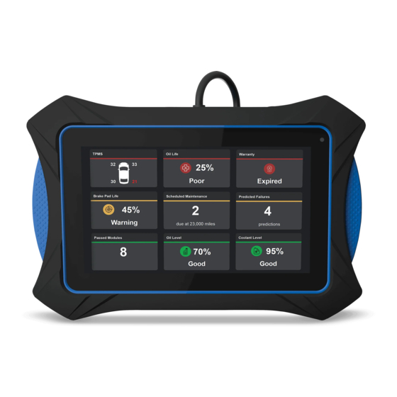
- Page 35 Using the Tablet VIEWING SCAN RESULTS Scheduled Maintenance The Scheduled Maintenance page provides a listing of scheduled maintenance procedures due at the next service interval. The Next Service field shows the odometer reading at which the associated service procedures are due. Each entry in the list shows a scheduled inspection or repair/ replacement procedure.
- Page 36 Using the Tablet VIEWING SCAN RESULTS Each entry in the list provides the following information: Predicted Failure(s) within 12 months: A brief description of the predicted failure/repair/maintenance procedure required. Probability of Failure: Expressed as a percentage of 100; shows a ...
- Page 37 Using the Tablet VIEWING SCAN RESULTS Viewing Vehicle Information and Customer Information The Additional Vehicle Information and Customer Information fields are accessed from Global OBD, Overview or Failed Modules page of the scan results screen (see VIEWING SCAN RESULTS on page 25). The Additional Vehicle Information field shows the following information: VIN: The complete Vehicle Identification Number...
- Page 38 If this is the first time you are creating a report, “Terms of Use and Privacy Policy Confirmation” message displays. Tap Terms of Use or Privacy Policy to view Innova’s Terms of Use and Privacy Policy pages. 5. Tap the Create Report! button on the “Terms of Use and Privacy Policy Confirmation”...
- Page 39 Using the Tablet PERFORMING A NETWORK SCAN 2. Turn the ignition ON. DO NOT start the engine. 3. Tap Vehicle Diagnostics. The Vehicle Diagnostics screen displays. 4. Refer to the appropriate paragraph for the diagnostic procedure you wish to perform: Network Scan –...
- Page 40 Using the Tablet SCANNING AND TESTING A SELECTED MODULE Enter the mileage shown on the vehicle’s odometer using the keyboard (see USING THE KEYBOARD on page 4), or, tap Pull From Vehicle to retrieve the current mileage from the odometer, then tap Submit.
- Page 41 Using the Tablet SCANNING AND TESTING A SELECTED MODULE Actions that are not available for the selected module are “grayed” out. 3. Refer to the appropriate paragraph for the diagnostic procedure you wish to perform: Read DTCs – see Reading DTCs for a Selected Module on ...
- Page 42 Using the Tablet SCANNING AND TESTING A SELECTED MODULE Each entry shows the DTC number, type, and definition. If no DTCs for the selected module are currently stored in the vehicle’s computer, the message “Fail” displays. 3. Tap an entry in the “breadcrumbs” trail at the top of the screen to return to a previous screen.
- Page 43 Using the Tablet SCANNING AND TESTING A SELECTED MODULE Performing Actuator Tests for a Selected Module Actuator Tests let you perform active tests for various vehicle actuators and systems. The specific tests available depend on the vehicle make and model. 1.
- Page 44 Using the Tablet SCANNING AND TESTING A SELECTED MODULE 5. Tap the appropriate control to operate the actuator as desired. The screen refreshes to show the result. 6. Repeat step 5 as desired. 7. Tap Back to return to the Actuator Test menu. Performing Special Tests for a Selected Module Special Tests let you perform diagnostic and calibration procedures for various vehicle actuators and systems.
- Page 45 Using the Tablet GLOBAL LIVE DATA – LIVE DATA MODE 4. Follow the on-screen prompts to prepare the vehicle for testing, and to perform the selected test procedure. A “results” screen displays when the test procedure has completed. 5. Tap Finish or Exit to return to the previous menu. 6.
- Page 46 Using the Tablet LIVE DATA MODE 1. Place the tablet in Live Data mode using the desired procedure (see Viewing Live Data for a Selected Module on page 40, GLOBAL LIVE DATA on page 43, or VIEWING LIVE DATA on page 62, as appropriate.
- Page 47 Using the Tablet LIVE DATA MODE details. You may also choose to record Live Data for later viewing. See Recording (Capturing) Live Data on page 45 for details. Customizing Live Data You can customize the Live Data display by selecting only the PIDs that you wish to display.
- Page 48 Using the Tablet ERASING DIAGNOSTIC TROUBLE CODES (DTCs) 3. A “Recording Complete” dialog displays the message “Would you like to save the recorded live data?” Tap Yes, Save Live Data to save the recorded data to tablet’s memory subsequent playback (see The Live Data Tab on page 63).
- Page 49 Using the Tablet ERASING DIAGNOSTIC TROUBLE CODES (DTCs) 5. If you chose to erase DTCs, a “One moment please…” message displays while the erase function is in progress. If the erase was successful, a confirmation message shows. erase successful, advisory message shows indicating...
- Page 50 Additional Tests OBD MODE TESTS OBD MODE TESTS OBD mode tests are accessed from the Global OBD, Overview or Failed Modules page of the scan results screen (see VIEWING SCAN RESULTS on page 25).. The following functions are available: Inspection/Maintenance Monitor Test ($01) – Lets you view the ...
- Page 51 Additional Tests OBD MODE TESTS The right column of the page shows the Drive Cycle procedure for the currently selected monitor. 2. Tap a monitor name to view the Drive Cycle procedure for the selected monitor. The page refreshes to display the Drive Cycle procedure for the ...
- Page 52 Additional Tests OBD MODE TESTS Test ID number Component ID number(s) Test Value Min or Max test limit Only one test limit, either Min or Max, is shown for any given test. Unit of measurement Status ...
- Page 53 Additional Tests IN-USE PERFORMANCE TRACKING (IPT) - PERFORMING SERVICE RESETS VIEWING IN-USE PERFORMANCE TRACKING (IPT) The tablet can retrieve In-use Performance Tracking (IPT) statistics for monitors supported by the vehicle under test. Two values are returned for each monitor; the number of times that all conditions necessary for a specific monitor to detect a malfunction have been encountered (XXXCOND), and the number of times that the vehicle has been operated under the specific conditions for the monitor (XXXCOMP).
- Page 54 Additional Tests PERFORMING SERVICE RESETS Tap an option on the Service Reset screen to initiate the associated procedure or process. - Tap an entry in the “breadcrumbs” trail at the top of the screen to return to a previous screen. When performing Service Reset procedures, a “One moment please”...
- Page 55 Additional Tests PERFORMING SERVICE RESETS The Battery Reset menu displays. 2. Tap Battery Reset Procedures. The Battery Reset Procedures menu displays. The menu provides access to General Information, and procedures to be followed Before Battery Disconnection, Before Battery Connection, and After Battery Connection.
- Page 56 Additional Tests PERFORMING SERVICE RESETS The Battery Reset menu displays. 2. Tap Reset Battery Monitoring System. An “instructional” message displays. 3. Follow the instructions provided to prepare the vehicle for battery reset OBD service. When all necessary procedures have been performed, tap Next to continue.
- Page 57 Additional Tests PERFORMING SERVICE RESETS 1. Tap Electric Parking Brakes on the Service Reset screen. For some vehicles, one or more submenus display. Tap the desired module and/or option, as appropriate. Proceed to step 2. If Electric Parking Brake reset is not supported by the vehicle under test, an “advisory”...
- Page 58 Additional Tests PERFORMING SERVICE RESETS If the procedure is stopped due to a communication error, an “advisory” message displays. Tap Exit to return to the Service Reset screen. 4. Tap OK to return to the Service Reset screen. Steering Angle Reset The Steering Angle Reset function is available for BMW, Chrysler, Ford, GM, Hyundai, Nissan, Toyota, Volkswagen and Volvo vehicles only.
- Page 59 Additional Tests PERFORMING SERVICE RESETS Perform test procedures as directed. Tap Next, as appropriate, to scroll to the next screen. 3. For some vehicles, “status” screens display as each phase of the calibration procedure is successfully completed. Tap Next, as appropriate, to scroll to the next screen.
- Page 60 Additional Tests PERFORMING SERVICE RESETS 5. Tap Service Reset in the “breadcrumbs” trail to return to the Service Reset screen. Battery / Alternator Test The tablet can perform a check of the vehicle’s battery and alternator system to ensure the system is operating within acceptable limits. You can perform a battery check only, or an alternator system (battery and alternator) check.
- Page 61 Additional Tests PERFORMING SERVICE RESETS 5. Turn the vehicle’s headlights on, then tap Continue to proceed. A “countdown” message shows while the battery check is in process. If battery voltage is less than 12.1 volts, an advisory message shows.
- Page 62 Additional Tests VIEWING DRIVE CYCLE PROCEDURES 3. Start and warm the engine to normal operating temperature. Turn on the headlights. Tap Continue to proceed. An “instructional” message shows. 4. Press the accelerator pedal to raise engine speed to 2000 RPM, and maintain the engine speed.
- Page 63 History: Displays the History Page from which you can view data stored in the tablet’s memory for previously scanned vehicles (see THE HISTORY PAGE on page 62). Support: Lets you contact Innova Technical Support or report an issue (See CONTACTING TECHNICAL SUPPORT on page 63).
- Page 64 Additional Tests VIEWING LIVE DATA – THE HISTORY PAGE VIEWING LIVE DATA You can view Live Data for the currently selected module. While linked to the vehicle, start the engine. From the Main Menu (see THE MAIN MENU on page 60), tap ...
- Page 65 If desired, use the View Table and View Graph buttons to toggle the display between graph mode and tabular mode during playback. CONTACTING TECHNICAL SUPPORT The Support option in the Main Menu lets you send an email to Innova Technical Support, or report an issue.
- Page 66 Technical; Support using the keyboard (see USING THE KEYBOARD on page 4). 5. Tap the Send button to send your email to Innova Technical Support. To cancel your message without sending, tap Cancel to return to the Technical Support dialog.
- Page 67 Additional Tests CONTACTING TECHNICAL SUPPORT To report an issue: 1. Tap Report An Issue. The Report an Issue page displays. 2. Tap the type of issue you wish to report; OBD II, ECM DTC, ABS DTC or SRS DTC. An instructional dialog displays.
- Page 68 Custom Scan Setup: Lets you specify the data to be included when performing a Custom Scan. Technical Support: Lets you send an email to Innova Technical Support. Date and Time Settings: Lets you set the current date and time for ...
- Page 69 4. When all data elements have been configured as desired, tap Save Settings to save your changes. A confirmation message displays. Tap Close to close the message. Emailing Technical Support Innova Technical Support is available Monday through Saturday, 6:00AM to 6:00PM, Pacific Time.
- Page 70 address using the keyboard (see USING THE KEYBOARD on page 4). 5. Tap the Message text box, then enter your message to Innova Technical; Support using the keyboard (see USING THE KEYBOARD on page 4). 6. Tap Send to send your email to Innova Technical Support.
- Page 71 Additional Tests SETTINGS Scroll the “month,” “day,” and “year” fields to set the current calendar date, then click DONE. Click CANCEL to close the Set Date dialog and retain the previous date. 3. To specify the current time: Tap the time format field. ...
- Page 72 Additional Tests SETTINGS Tap Change Network. The Sign In To Your Wi-Fi Network dialog displays. The dialog lists all available Wi-Fi networks within range of the tablet. 3. Swipe up or down to scroll to the desired Wi-Fi network, then tap the network name.
- Page 73 Additional Tests SETTINGS Setting the Display Language 1. Scroll the Settings page to the Language field. 2. Tap the currently active language to display the Select Language menu. Select the radio button for the desired language, then tap OK. Click CANCEL to close the Select Language menu and retain the previously selected display language.
- Page 74 Additional Tests SETTINGS Using the DLC Locator 1. Scroll the Settings page to the DLC Locator field. 2. Tap Make to display the Select Make menu. Select the radio button for the desired vehicle manufacturer, then tap OK 3. Tap Year to display the Select Year menu.
- Page 75 Additional Tests SETTINGS 3. Tap Report An Issue to open the Support page (see Contacting Technical Support on page ##). Exiting the Settings Mode Tap the Menu icon to open the Menu panel, then tap Home to return to the Home page.
- Page 76 Notes...
- Page 77 UPDATES and OPTIONAL ACCESSORIES, please contact your local store, distributor or the Service Center. USA & Canada: (800) 544-4124 (6:00 AM-6:00 PM PST, Monday through Saturday) All others: (714) 241-6802 (6:00 AM-6:00 PM PST, Monday through Saturday) FAX: (714) 241-3979 (24 hr.) Web: www.innova.com...
Need help?
Do you have a question about the 7111 and is the answer not in the manual?
Questions and answers
after attempting an update on the innvoa 7111, it stopped mid way, now its been bricked and just starts up and then says the program has stopped and keeps reseting, anyway to fix this ?