Druck DPI611 Instruction Manual
Portable pressure calibrator
Hide thumbs
Also See for DPI611:
- Safety and quick start manual (109 pages) ,
- Installation manual (94 pages)
Table of Contents
Advertisement
Quick Links
Advertisement
Table of Contents

Related Manuals for Druck DPI611


Summary of Contents for Druck DPI611
- Page 1 DPI611 Portable Pressure Calibrator Instruction Manual Druck.com...
- Page 3 Introduction The Druck DPI611 is a fully self-contained pressure test and calibration system that combines pressure generation, signal measurement and loop power. It provides all the convenience of the Druck DPI610/615 series with significantly improved generation capabilities, higher accuracy and simplified touch screen operation.
- Page 4 Ground (Earth) DC adaptor polarity: the Centre of the plug is negative. Druck is an active participant in the UK and EU Waste Electrical and Electronic Equipment (WEEE) take-back initiative (UK SI 2013/3113, EU directive 2012/19/EU). The equipment that you bought has required the extraction and use of natural resources for its production.
- Page 5 Digital Pressure Instrument Device Under Test etc. And so on e.g. For example Full Scale Foot Gauge Water Hertz IDOS Intelligent Digital Output Sensor (Druck product) i.e. That is Inch kilogram Metre milliampere Maximum mbar millibar Minute or minimum MSDS...
- Page 6 Copyright 2014 Baker Hughes Company. iv | DPI611 Instruction Manual–English...
-
Page 7: Table Of Contents
Upgrade the Application Software 1.13.4 Upgrade the Operating System and Boot Loader Software 1.14 Maintenance 1.14.1 Cleaning 1.14.2 Replace the Batteries 1.15 Instrument Return 1.15.1 Returned Material Procedure 1.15.2 Safety Precautions Copyright 2014 Baker Hughes Company. English–DPI611 Instruction Manual | v... - Page 8 Define Each Input Channel Analysis Function Run Procedure 4.4.1 Sequence to Upload and Download File Calibration General Calibration Check Calibration Adjustments Before Starting Procedures: Current (Measure) Procedures: Current (Source) Procedures: DC mV/Volts (Measure) Copyright 2014 Baker Hughes Company. vi | DPI611 Instruction Manual–English...
- Page 9 5.10 Procedures: IDOS UPM Accessory Instructions Dirt Moisture Trap 20 bar (P/N IO620-IDT621) 6.1.1 Specification 6.1.2 Pressure Connections 6.1.3 Operation 6.1.4 Cleaning Leak Test Procedure Pressure Vacuum General Specification Troubleshooting Pressure Generation General Copyright 2014 Baker Hughes Company. English–DPI611 Instruction Manual | vii...
- Page 10 Copyright 2014 Baker Hughes Company. viii | DPI611 Instruction Manual–English...
-
Page 11: Introduction
Refer to DPI611 datasheet for full list of accessories supplied with each DPI611 model. 1.2 Observance of the User Manual This manual contains safety and battery installation information for the Druck DPI611. It is the responsibility of the customer to make sure that all personnel operating and maintaining the equipment are correctly trained and qualified. -
Page 12: Warnings
1.5 Electrical Safety WARNING The DC input to the DPI611 is rated at 5 Vdc ± 5% 4 Amps. External circuits should have appropriate insulation to the mains. To prevent electrical shocks or damage to the instrument, do not connect more than 30 V CAT I between the terminals or between the terminals and the ground (earth). -
Page 13: Pressure Warnings
Pressure Warnings 1.6 Pressure Warnings WARNING It is dangerous to attach an external source of pressure to a DPI611 pressure calibrator. Use only the internal mechanisms to set and control pressure in the pressure calibrator. To prevent a dangerous release of pressure, isolate and bleed the system before disconnecting a pressure connection. - Page 14 Replace the battery cover by pressing the lugs (b) inside the slots (d) and bring down the cover, securing by tightening the fixing screw. (See Figure 1-1). Figure 1-1: Fit Dry Cell Batteries Copyright 2014 Baker Hughes Company. 4 | DPI611 Instruction Manual–English...
-
Page 15: Parts
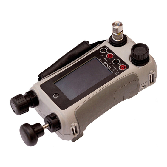
Parts 1.9 Parts 1.9.1 Overview Figure 1-2: DPI611 Pressure Calibrator Item Description On/Off button. Pump mechanism and pressure/vacuum selector. Pneumatic volume adjuster. Test port: To attach the device under test. Pneumatic pressure release valve to release pressure in the system. -
Page 16: Test Port
Figure 1-5: Selector This control sets the operation of the instrument (pressure or vacuum). To prevent a pressure leak, turn it fully clockwise or counter-clockwise. (+ : Pressure, - : Vacuum) Copyright 2014 Baker Hughes Company. 6 | DPI611 Instruction Manual–English... -
Page 17: Pump
Fine adjustments of pressure can be made using the volume adjuster (See Section 1.9.6). 1.9.6 Volume Adjuster Figure 1-7: DPI611 Volume Adjuster This control increases or decreases the pressure/vacuum. Before sealing the system (See Section 1.9.3), turn this control to the necessary position: •... -
Page 18: Accessories
Chapter 1. Introduction 1.10 Accessories 1.10.1 Carry Case (P/N IO611-CASE-1) A tailored fabric carry case with carrying strap allows the DPI611 to be used without removing it from the case. 1.10.2 Rechargeable Battery Pack (P/N CC3800GE) Use in place of AA cells. The battery pack is charged within the instrument. -
Page 19: Mains Adaptor (P/N Io620-Psu)
It connects the DPI611 to a PC via a USB port. 1.10.6 IDOS to USB Converter (P/N IO620-IDOS-USB) It allows connection of an IDOS universal pressure module to the DPI611. USB Cable (P/N IO620-USB-PC) is also required to connect the converter to the DPI611 USB port. -
Page 20: Pneumatic Hose (P/N Io620-Hose-P1 / Io620-Hose-P2)
2 m / 6.4 ft Pneumatic Hose - 20 bar (300 psi) 1.10.11 Pressure Adaptor Set A set of test point adaptors to connect the tool-less quick fit DPI611 pressure port or the extension hoses to the device under test. -
Page 21: Comparator Adaptor (P/N Io620-Comp)
For greater efficiency, two test devices can be connected at the same time. The adaptor connects to the pressure port of the DPI611 and provides two outlet ports. It is compatible with the standard adaptors supplied and the adaptor kits. -
Page 22: Power Up From Standby Mode
DASHBOARD >> SETTINGS >> DATE Note: The DPI611 will maintain the date and time for 30 days after being left without batteries. In case of loss of date and time, replace the batteries, connect the mains adaptor to the DPI611 and keep it turned on for 50 hours to fully recharge the clock battery. -
Page 23: Software And Firmware Upgrades
To make sure the upgrade completed correctly, use the Status menu. 1.14 Maintenance The DPI611 instrument contains no user serviceable parts and should be returned to a Druck service center or an approved service agent for all repairs. For more information, contact our customer service department at: https://druck.com/service. -
Page 24: Instrument Return
Chapter 1. Introduction 1.15 Instrument Return 1.15.1 Returned Material Procedure If the unit requires calibration or is unserviceable, return it to the nearest Druck Service Centre listed at: https://druck.com/service. Contact the Service Department to obtain a Return Goods/Material Authorization (RGA or RMA). -
Page 25: Operations
Use only the internal mechanisms to set and control pressure in the pressure calibrator. 2.1.1 Introduction This section gives examples of how to connect and use the DPI611 pressure calibrator for the necessary pressure or vacuum operations. Before you start: •... -
Page 26: Attach/Remove The Device Under Test
Re-attach the adaptor to the test port and tighten it until it is hand-tight only. 2.1.3.2 Procedure to Remove To remove a device, first release the pressure (See Section 2.1.2). Copyright 2014 Baker Hughes Company. 16 | DPI611 Instruction Manual–English... -
Page 27: Vacuum Or Pressure Operation
Use the pump to set the maximum pressure or set the pressure you want to adjust. Adjust the pressure. Clockwise to decrease; counter-clockwise to increase. 2.2 Calibrator Operations 2.2.1 Basic Calibrator Operation Select: DASHBOARD >> CALIBRATOR Copyright 2014 Baker Hughes Company. English–DPI611 Instruction Manual | 17... - Page 28 Note: Saved Function is what is currently active in the calibrator window. It is NOT a selected Task - refer to COPY TASK to copy selected Task to the Favourites. 2.2.1.2 Calibrator Select CALIBRATOR from the TASK MENU. Copyright 2014 Baker Hughes Company. 18 | DPI611 Instruction Manual–English...
- Page 29 This will allow the user to select from commonly used combinations of functions. Figure 2-6: Calibrator Select the required function by touching either the appropriate text or diagram. The DPI611 will set the functions and return to the main Calibrator screen.
- Page 30 Selecting FAVOURITES from the TASK MENU allows selection of all SAVED and COPIED tasks. Figure 2-8: Favourites Select the required function by touching either the appropriate text or diagram. The DPI611 will set the functions and return to the main calibrator screen. Task can be deleted by selecting DELETE.
-
Page 31: Set The Function Utility Options
For each function only one utility may be active. Not all source and measure functions have associated utilities. For all options, the button resets the additional readings. 2.2.2.1 Max/Min/Avg Max/Min/Avg utility is only available with measure functions. Copyright 2014 Baker Hughes Company. English–DPI611 Instruction Manual | 21... - Page 32 This utility can be used with Ramp Automation, where the rising signal causes the switch to change state and the falling signal causes the switch to resume its’ original state. Figure 2-12: Switch Test Example Copyright 2014 Baker Hughes Company. 22 | DPI611 Instruction Manual–English...
-
Page 33: Measurement Display Options
Rising Falling Maximum Maximum Minimum Minimum Figure 2-14: Relief Valve Utility 2.2.3 Measurement Display Options There are two display views in the CALIBRATOR screen when multiple channels are in use: Copyright 2014 Baker Hughes Company. English–DPI611 Instruction Manual | 23... -
Page 34: Example Procedures
2.2.4 Example Procedures 2.2.4.1 Example Procedure: Measure or Source Current with Internal Loop Power Figure 2-17 shows CH1 set-up to measure or source a current with internal loop power. Copyright 2014 Baker Hughes Company. 24 | DPI611 Instruction Manual–English... - Page 35 Calibrator Operations Note: Loop drive is provided by connecting to the two red terminals on the front of the DPI611 and enabling Current (24V) as the electrical function. mA 24V DPI611 Figure 2-17: Measure Current on CH1. Range ± 55 mA Set the applicable software options.
- Page 36 Complete the electrical connections and continue with the measure or source operation. Source only (Automation): Set the applicable output value. 2.2.4.4 Example Procedure: Switch Test Switch Test is only valid when a Pressure Function is selected. Copyright 2014 Baker Hughes Company. 26 | DPI611 Instruction Manual–English...
- Page 37 2.2.4.5 Example Procedure: Measure Voltage with Internal Voltage Source Figure 2-22 shows CH1 set-up to measure a DC voltage. (± 30 V) or DC mV (± 2000 mV) with Internal Voltage Source (e.g. for use with Resistive bridge). Copyright 2014 Baker Hughes Company. English–DPI611 Instruction Manual | 27...
-
Page 38: Pressure Calibration
Chapter 2. Operations Note: Internal Voltage is provided by connecting to the Vo terminals on the front of the DPI611 and enabling Voltage (10V) or Millivolts (10V) as the electrical function. mA 24V DPI611 Figure 2-22: Measure DC Volts (10V) or DC mV (10V) on CH1 Set the applicable software options. -
Page 39: Set Up A Leak Test
This utility provides a test to calculate the leak of a system. Figure 2-24: Leak Test Example To configure leak test: Set the Utility to Leak Test. Select: SETTINGS >> LEAK TEST Copyright 2014 Baker Hughes Company. English–DPI611 Instruction Manual | 29... -
Page 40: Set The Pressure Module To Zero
Optional item. An IDOS Universal Pressure Module (UPM) uses Intelligent Digital Output Sensor (IDOS) technology to measure the applied pressure and supply the data to an IDOS instrument. Before using an IDOS module, refer to instruction manual K0378. Copyright 2014 Baker Hughes Company. 30 | DPI611 Instruction Manual–English... -
Page 41: Idos Option Assembly Instructions
Measure Pressure: IDOS Option To attach an IDOS module to the Druck DPI611 use an IO620-IDOS-USB adaptor. Figure 2-25: IDOS Module 2.4.1 IDOS Option Assembly Instructions Attach one end of the adaptor IO620-IDOS-USB to the IDOS module. Push the Type A end of USB Cable into the USB socket on the instrument and the Type B end into the adaptor (IO620-IDOS-USB). - Page 42 Chapter 2. Operations Copyright 2014 Baker Hughes Company. 32 | DPI611 Instruction Manual–English...
-
Page 43: Data Logging
The data is stored in the internal memory or on a USB Flash Drive connected to the Unit until the Data Logging is stopped. 3.1 Set-up Before starting, set all channels to the correct functions. (See Chapter 2). To access the Data logging function do the following: Copyright 2014 Baker Hughes Company. English–DPI611 Instruction Manual | 33... -
Page 44: Operation
In Key press mode, a data point is taken every time the user taps the log button To stop Data Logging select The data logging indicator flashes to indicate whenever a reading is logged. Copyright 2014 Baker Hughes Company. 34 | DPI611 Instruction Manual–English... -
Page 45: File Review
Select file and tap tick bottom right on the screen to erase. • CLEAR INTERNAL Clears all internal files. 3.4.3 Memory Status The MEMORY STATUS button will show the amount of available memory in the areas that follow: • Internal Copyright 2014 Baker Hughes Company. English–DPI611 Instruction Manual | 35... -
Page 46: Data Format
1, 10 Aug 2021, 10:00:15,8.5711,24V,4,0,False 2, 10 Aug 2021, 10:00:30,8.4080,24V,4,0,False 3, 10 Aug 2021, 10:00:45,8.2475,24V,4,0,False 4, 10 Aug 2021, 10:01:00,8.0733,24V,4,0,False 5, 10 Aug 2021, 10:01:15,7.9288,24V,4,0,False Figure 3-3: Example ‘csv’ Data Log File Copyright 2014 Baker Hughes Company. 36 | DPI611 Instruction Manual–English... -
Page 47: Documentation
ANALYSIS • RUN PROCEDURE 4.1 Analysis The Analysis function takes readings from two or more DPI611 channels to calibrate the transfer characteristic of the device being tested. One channel is the Reference channel and is used as follows: • It provides a measure of the input signal to the device. -
Page 48: Define The Reference Channel
Tap the channel button that is to be used as the Reference channel for the analysis. Figure 4-1: Select Reference Channel Set the channel type to Reference. All other channel settings for that channel are canceled. All other active channels are set to Input. Copyright 2014 Baker Hughes Company. 38 | DPI611 Instruction Manual–English... -
Page 49: Define Each Input Channel
The test limits for the deviation from the transfer characteristic. 4.3 Analysis Function Set Input channel parameters (See Section 4.2), and return to CHANNEL SETUP screen. Select the Start button The Analysis window displays the following: Copyright 2014 Baker Hughes Company. English–DPI611 Instruction Manual | 39... -
Page 50: Run Procedure
Use the Download button in calibrator manager to Download the file to the Druck DPI611 calibrator. A communications symbol will be displayed at the bottom of the screen. - Page 51 When all the readings are complete, tap on the Exit Button . Look at the results on the display (As found/As Left). To complete the process, use the calibrator manager to Upload the file back into the 4Sight2™ database. Copyright 2014 Baker Hughes Company. English–DPI611 Instruction Manual | 41...
- Page 52 Chapter 4. Documentation Copyright 2014 Baker Hughes Company. 42 | DPI611 Instruction Manual–English...
-
Page 53: Calibration
The DPI611 is a very precise measuring instrument and the test equipment and conditions of test must be suitable for the type of work. The calibration check and calibration adjustment should be carried out in a controlled environment by a calibration technician. -
Page 54: Procedures: Current (Measure)
Check the calibration is correct. Select the applicable Current (measure) function. Apply the values that follow: mA: -55, -25, -20, -10, -5, 0 (open circuit) mA: 0, 5, 10, 20, 25, 55 Copyright 2014 Baker Hughes Company. 44 | DPI611 Instruction Manual–English... -
Page 55: Procedures: Current (Source)
5.7 Procedures: DC mV/Volts (Measure) Do the procedure as follows: Connect the applicable calibration equipment (See Table 5-1). Let the equipment get to a stable temperature (minimum: 5 minutes since the last power on). Copyright 2014 Baker Hughes Company. English–DPI611 Instruction Manual | 45... -
Page 56: Procedures: Dc Volts (Source)
5.8 Procedures: DC Volts (Source) Do the procedure as follows: Connect the applicable calibration equipment (See Table 5-1). Let the equipment get to a stable temperature (minimum: 5 minutes since the last power on). Copyright 2014 Baker Hughes Company. 46 | DPI611 Instruction Manual–English... -
Page 57: Procedures: Pressure Indicator
Check the error is within limits. From the datasheet use the values in the Accuracy column. 5.10 Procedures: IDOS UPM (Refer: User Manual IDOS UPM). When the calibration is complete, the instrument automatically sets a new calibration date in the UPM. Copyright 2014 Baker Hughes Company. English–DPI611 Instruction Manual | 47... - Page 58 Chapter 5. Calibration Copyright 2014 Baker Hughes Company. 48 | DPI611 Instruction Manual–English...
-
Page 59: Accessory Instructions
This device is designed for use on the DPI611 pressure calibrator. Fit the Dirt Moisture Trap to the Test Station of the DPI611. If moisture or particles are seen within the transparent chamber during use, dismantle and clean the trap. (See Section 6.1.4). -
Page 60: Cleaning
Unscrew the top section, releasing the transparent chamber. Clean the components. Wipe clean with a soft cloth or tissue paper. Re-assemble ensuring that all seals are in the correct location. Copyright 2014 Baker Hughes Company. 50 | DPI611 Instruction Manual–English... -
Page 61: Leak Test Procedure
Pressure 7. Leak Test Procedure This section describes the leak test procedures for the following DPI611 pressure ranges: DPI611 Pressure Range 20 bar (300 psi / 2 MPa) 10 bar (150 psi / 1 MPa) 7 bar (100 psi / 700 kPa) -
Page 62: Vacuum
Allow the vacuum to stabilize for 1 minute. Start the Leak Test, noting the leak rate indicated after test complete. The Leak Rate over 1 minute should not exceed 0.005 bar/min. Copyright 2014 Baker Hughes Company. 52 | DPI611 Instruction Manual–English... -
Page 63: General Specification
8. General Specification For a full specification of the Druck DPI611 calibrator and its related accessories refer to the relevant product datasheet. The DPI611 is suitable for indoor use with the following environmental requirements. It is permitted to use the DPI611 outdoors as a portable instrument if the environmental requirements are met. - Page 64 Chapter 8. General Specification Copyright 2014 Baker Hughes Company. 54 | DPI611 Instruction Manual–English...
-
Page 65: Troubleshooting
DUT has leak. Isolate DUT from DPI611 and check for leaks in DPI611 and DUT independently. Worn pressure seal on outlet port Inspect seal on pressure port for (o-ring & backup ring). - Page 66 Chapter 9. Troubleshooting Copyright 2014 Baker Hughes Company. 56 | DPI611 Instruction Manual–English...
- Page 68 Office Locations https://druck.com/contact Services and Support Locations https://druck.com/service Copyright 2014 Baker Hughes Company. This material contains one or more registered trademarks of Baker Hughes Company and its subsidiaries in one or more countries. All third- party product and company names are trademarks of their respective holders.
Need help?
Do you have a question about the DPI611 and is the answer not in the manual?
Questions and answers