Table of Contents
Advertisement
Quick Links
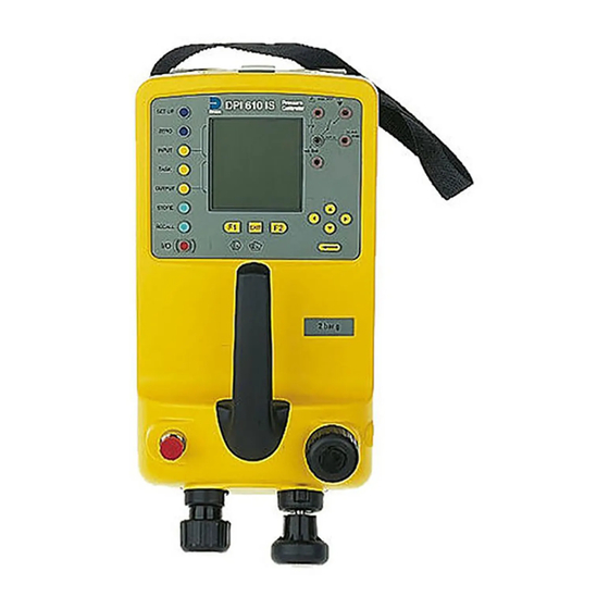
DPI 610 IS
PORTABLE PRESSURE CALIBRATOR/INDICATOR
USER GUIDE
K239
Calibrator Version
Indicator Version
Hydraulic Calibrator Version
DPI 610 IS Portable Pressure Calibrator
Software version 1.XX
© Druck Ltd. 1999
This document is the property of Druck Limited and may not, either in part or whole, be
copied or otherwise reproduced, communicated in any way to third parties nor stored in any
Data Processing system, without the express written authority of Druck Limited.
K239 Issue No. 1
i
Advertisement
Table of Contents

Related Manuals for Druck DPI 610 IS


Summary of Contents for Druck DPI 610 IS
- Page 1 Software version 1.XX © Druck Ltd. 1999 This document is the property of Druck Limited and may not, either in part or whole, be copied or otherwise reproduced, communicated in any way to third parties nor stored in any Data Processing system, without the express written authority of Druck Limited.
- Page 2 Attention is drawn to Pages 4/5 of the Certificate of conformity for electrical connection parameters SPECIAL CONDITION OF USE The DPI 610 IS Series Pressure calibrator is NOT capable of withstanding the 500V r.m.s. electric strength test between the external connectors and the frame of the apparatus as required by Clause 6.4.12 of EN50020 and this must be taken...
- Page 3 The instrument must be maintained, either by the manufacturer or a competent person. Please refer to supplier for details of approved service agents. A list of Druck Subsidiaries who will be able to assist and advise is given on Page 38.
- Page 4 Specification Pressure Ranges (Internal Transducers) Accuracy Combined non-linearity, Hysteresis and repeatability 70 mbar to 20 bar (Calibrator): 0.025% F.S. 35 bar to 700 bar (Indicator): 0.025% F.S. 70 bar to 400 bar (Hydraulic) 0.025% F.S. Temperature Effects ±0.004% of reading/°C (averaged over -10° to -40°C w.r.t. 20°C) Electrical Parameters Voltage Inputs Range:...
-
Page 5: Table Of Contents
Contents Introduction General Description of Procedures Using the Guide Summary of Functions OPERATOR CONTROLS DISPLAY HARD KEY FUNCTIONS SOFT KEYS CURSOR KEYS ELECTRICAL CONNECTIONS Getting Started Fitting Batteries Switching On Change Pressure Units Voltage and Current Measurements Typical Calibration Set-up (Pressure to Voltage) Zero Display Reading Making Measurements Basic Mode (Task BASIC) - Page 6 Contents (Contd.) Advanced Task (contd.) Electrical Outputs (Loop Power) mA Step mA Ramp mA Value Define New Task Clear Task Memory Operations Saving Display or Datalog Store Operations Recalling Stored Data Datalog Operations Auto Log (Timer) Manual Logging Recall Datalog Files Downloading Datalog Files Delete Datalog Files Using Set-up...
- Page 7 Contents (Contd.) Appendix 1 - Hydraulic Actuator version Introduction Safety Instructions Preparation for Use Bleeding the System Operation Draining the Hydraulic Fluid Flushing, replenishing or Changing the Hydraulic Fluid Appendix 2 - Baseefa Certificate of Conformity K239 Issue No. 1...
- Page 8 Notes (This page intentionally blank) K239 Issue No. 1 viii...
-
Page 9: General
INTRODUCTION Summary of Functions General The DPI 610 is a rugged, portable precision instrument available either as an indicator or calibrator for use in hazardous areas. Additionally, an intrinsically safe hydraulic calibrator version (HC) is available. The instrument is primarily used for calibrating instrumentation and systems over the range -1 to 20 bar, (HC version to 400 bar). -
Page 10: Using The Guide
INTRODUCTION Summary of Functions Using This Guide The following key symbols are used in the procedure diagrams which follow Shaded cursor keys indicate that a combination of these four keys, Up, Down, Left and Right should be used to (e.g.) enter an alpha numeric value or to select a function. -
Page 11: Summary Of Functions
These divide into two groups, the operator/display controls (shown in Figure 1) and the pressure/vacuum generation components (Shown in Figure 2). The operator controls and a typical display, common to all instrument versions, is shown below. Display max 30V DPI 610 IS TASK: BASIC Electrical Measurement Input Sockets VOLTAGE... -
Page 12: Hard Key Functions
INTRODUCTION Summary of Functions HARD KEY FUNCTIONS (Fig. 1) g i f o i t t l u i l e . y r h t i h t i t l u g i f f i d b i l o i t g i f o i t... -
Page 13: Soft Keys
INTRODUCTION Summary of Functions SOFT KEYS (Fig.1) Three soft keys, designated F1, EXIT and F2, are situated immediately below the display as shown below. These keys have their function allocated by the instrument software which is indicated in the bottom of the display (Voltage for F1 and Units for F2 in this example). -
Page 14: Electrical Connections
Temperature Sensor Figure 3 - Electrical System Connections Measurement inputs and Source Outputs are made via the control panel sockets as shown below. Input Window max 30V DPI 610 IS CAT II TASK: BASIC Electrical Measurement Input Sockets INPUTS VOLTAGE... -
Page 15: Getting Started
Getting Started Fitting Batteries Cover fixing screws Cover fixing screws l a i Six Alkaline C-cells (Type only as Table) l l e l l e Low battery indicator TASK: BASIC VOLTAGE PRESSURE INT CURRENT PRESSURE UNITS WARNING: BATTERIES MUST ONLY BE FITTED IN A SAFE AREA. USE ONLY THE BATTERIES SPECIFIED IN THE TABLE. -
Page 16: Change Pressure Units
Getting Started Change Pressure Units To change the pressure units proceed as follows. If the four units displayed are not the units required, press TASK and select any task, other than BASIC, press SETUP and proceed as detailed on page 31. To return to BASIC mode, press TASK and select BASIC. -
Page 17: Typical Calibration Setup (Pressure To Voltage)
SAFE Ext Press. Source (Indicator Only) SUPPLY BARRIER SAFE Pressure Regulator Max 30V DPI 610 IS CAT II TASK: BASIC VOLTAGE PRESSURE INT PRESSURE CURRENT UNITS General Procedure Use the handpump to pressurise the system to the required level as indicated on the display. -
Page 18: Making Measurements
SAFE Ext Press. Source (Indicator Only) SUPPLY BARRIER SAFE max 30V Pressure DPI 610 IS Regulator TASK : P-I SNAPSHOT MODE CURRENT PRESSURE INT Set Units Note: If the four units displayed are not the units required, press SETUP, select SETTINGS and refer to Page 31. -
Page 19: Pressure Converter (P-P) Task
Voltage Output Pressure Transmitter (P-V) Task SAFE Ext Press. Source (Indicator Only) SUPPLY BARRIER SAFE Pressure Regulator max 30V DPI 610 IS TASK : P-V SNAPSHOT MODE VOLTAGE PRESSURE INT If required, change pressure units using the OUTPUT key. K239 Issue No.1... -
Page 20: Current To Pressure Converter (I-P) Task
Making Measurements Current to Pressure Converter (I-P) Task Use the Up (Ù) and Down (Ú) cursor keys to adjust the loop current to the required value. Alternatively, press ENTER and use cursor keys to enter a finite value. Cursor keys can then be used to nudge the output either up or down. If required, change pressure units with INPUT key. -
Page 21: Pressure To Display (P-Display) Task
Store Mode menu as detailed on Page 30. Connect the device under test to the instrument as shown below. Ext Press. Source (Indicator Only) TEST UNIT (Dial Gauge) Pressure max 30V DPI 610 IS Regulator TASK : P-DISPLAY SNAPSHOT MODE DISPLAY PRESSURE INT CHANGE VALUE Press TASK and select P-DISPLAY. -
Page 22: Leak Tests (Leak Test) Task
Making Measurements Leak Test (LEAK TEST) Task Ext Press. Source (Indicator Only) EXTERNAL SYSTEM Pressure Regulator max 30V CAT II TASK : LEAK TEST SNAPSHOT MODE PRESSURE INT WAIT secs DURATION secs START PRESS STOP PRESS PRESS CHANGE LEAK RATE bar/m CHANGE VALUE... -
Page 23: Transmitter Simulator (Tx Sim) Task
Making Measurements Transmitter Simulator (TX SIM) Task When used with an external voltage source (see Page 22), provides a current output proportional to the calibrator’s measured output pressure (indicated pressure on indicator only version). Select task TX SIM. Press EXIT to skip setup screen if parameters are correct. -
Page 24: Relief Valve Test (Rel Valve) Task
Making Measurements Relief Valve Test (REL VALVE) Task To carry out a relief valve test, press TASK and select REL VALVE. Connect the output pressure port of the instrument to an external system as shown below. To change the pressure units, if required, press INPUT and select the required units by means of the cursor keys. -
Page 25: Advanced Task
Advanced Task Select Input General Advanced task allows the user to configure the instrument to monitor one of a number of different input measurands (Inputs) and outputs (Sources). Additionally, five process functions, Tare, Max/Min, Filter, Flow and % Span can be applied to the input functions. -
Page 26: Process Functions
Advanced Task Process Functions Process Functions If required, the following process functions are available on the Measurand (INPUT) display but only in ADVANCED task. If the instrument is in any other mode i.e. BASIC or any other task mode, the input and output displays must first be configured in ADVANCED task. -
Page 27: Tare Process Function
Advanced Task Process Functions Tare Process Function To set up a Tare function, enable TARE from the process menu and press F1 to enter the Tare SETTINGS functions. Disable TARE by entering process menu and turning the function OFF. Note: Last TARE setting is retained and will be applied when function is next enabled. -
Page 28: Min/Max Process Function
Advanced Task Process Functions Min/Max Process Function To set up an input display to show min/max and present measurand reading, enable MIN/MAX from the process menu and press F1 (SETTINGS) to provide RESET function. The display is now reconfigured to show the max/min values as follows (e.g.), Reset Max/Min display at any time by pressing the F1 key. -
Page 29: Flow Function
Advanced Task Process Functions Flow Function To apply the flow function to a selected measurand, enable FLOW from the process menu and press ENTER. The square root symbol is displayed beside the measurand to indicate that the FLOW function is active (e.g.) TASK : ADVANCED SNAPSHOT MODE To cancel FLOW, press INPUT and turn function... -
Page 30: Select Output
Advanced Task Select Output Select Output To select an output channel for display, select ADVANCED mode from the Task menu and proceed as follows. If a channel has a range of units available, a UNITS soft box (actioned by the F2 function key), will be also be written to the display. The following procedure shows the method of output channel selection. -
Page 31: Ma Step
Advanced Task Select Output mA Step To select one of the electrical output programs, press the OUTPUT key and proceed as follows (e.g.), On selection of (e.g.) Linear, the output display window changes to show the selected program of output currents (e.g.), TASK : ADVANCED TASK : ADVANCED SNAPSHOT MODE... -
Page 32: Ma Ramp
Advanced Task Select Output mA Ramp Press the OUTPUT key and select mA Ramp in a similar manner to that shown above. Define ramp required by entering START and END current values as shown below (e.g.), TASK : ADVANCED TASK : ADVANCED SNAPSHOT MODE SNAPSHOT MODE ENTER VALUE... -
Page 33: Ma Value
Advanced Task Select Output mA Value Press the OUTPUT key and select mA Value from the Output menu. The procedure is shown below (e.g.), SET LEVEL SELECT OUTPUT TASK : ADVANCED SELECT OUTPUT SNAPSHOT MODE PRESSURE INT PRESSURE EXT PRESSURE INT mA STEP mA RAMP OUTPUT... -
Page 34: Define New Task
Advanced Task Task Setup/Removal Define New Task To define a new task, proceed as follows. Select ADVANCED from TASK menu. Using the INPUT key, select the required measurand as the input display and setup any process functions required. Using the OUTPUT key, select the required measurand as the output display. Press TASK and select Free . -
Page 35: Memory Operations
Memory Operations Store Saving Display (Snapshot) or Datalog Memory operations depend upon how Store mode has been set-up. Three options are available None, Snapshot and Datalog. Refer to SETUP for details. Store Operations To store any display (menu displays excepted), press the STORE key. This saves the current display to the next available location. -
Page 36: Datalog Operations
Memory Operations Datalog Datalog Operations Datalog is a special application of store mode which enables the calibrator to either automatically log displays at preset time intervals or to manually log a display on operation of the STORE key. Logged data is written to a user specified file. To set up a datalog file, proceed as follows. -
Page 37: Recall Datalog Files
Memory Operations Datalog Recall Datalog Files To recall a datalog file to the display, ensure that DATALOG is selected from the SETUP menu, proceed as follows (e.g.), Downloading Datalog Files WARNING: This procedure must be carried out in a SAFE area. Connect the RS232 socket of the instrument into either the COM1 or COM2 port of the PC. -
Page 38: Using Setup
Using Setup General SETUP mode is available in all modes except BASIC. It permits the setup of the following instrument parameters. Store Mode - None, Snapshot, Datalog. Contrast. Instrument Settings - Units, Language, RS232 parameters, Powerdown, and Calibration Routines (Refer to page 33 for Calibration details) . Contrast Select CONTRAST from the Setup Menu and proceed as follows. -
Page 39: Settings - Select Setup Option
Using Setup Settings - Select Setup Option To select one of the Settings options from the Setup menu, proceed as follows. Units Select (pressure) Units from the Settings menu and proceed as follows. Define Special Units Select (pressure) Units from the Settings menu, and select Special Units and proceed as follows. -
Page 40: Language
Using Setup Language RS232 Select RS232 from the Settings Menu and proceed as follows. Note: Use of the RS 232 communications interface is only permitted in a SAFE area. The settings shown above are the default settings. Powerdown Select Powerdown from the Setup menu. The method of setting up the Powerdown (Auto Power Off) function is similar to that detailed for the Backlight (Page 30). -
Page 41: Calibration
90 day intervals. The DPI 610 is a very precise measuring instrument and the test equipment and conditions of test must be suitable for the type of work. The use of a Class A compensated deadweight tester is essential. -
Page 42: General Procedures
General Procedures The following general hints are provided as a guide to calibration procedures. Full calibration procedures are described in Druck publication number K235. Use high quality Repeatable and Linear pressure sources and allow adequate stabilisation time before calibration (minimum 1 hour). -
Page 43: Temperature
Calibration Temperature Precision Temperature Meter. On completion of calibration routines, exit the calibration mode by pressing the EXIT function key. K239 Issue No.1... -
Page 44: Service
Service Approved Service Agents The following are approved Service Agents for Druck Instruments. FRANCE JAPAN Druck SA, 19 Rue Maurice Pellerin, Druck Japan KK, Medie Corp Building 8, 92600 Asnières, France. 2-4-14 Kichijyoji-Honcho, Musashino, Tokyo 180, Japan. Tel: (1) 41 32 34 64... - Page 45 Appendix 1 HYDRAULIC CALIBRATOR VERSION K239 Issue No. 1...
-
Page 46: Introduction
HYDRAULIC CALIBRATOR VERSION Operation Introduction This version of the DPI 610 provides manual generation of hydraulic pressure and consists of a screw-press with a priming pump and priming isolation valve as shown below. The bleed pipe connections are also shown in Figure A1. BLEED HOSE ASSEMBLY DOWTY WASHER SCREWPRESS... -
Page 47: Safety Instructions
HYDRAULIC CALIBRATOR VERSION Operation Safety Instructions WARNING HYDRAULIC FLUID IS INJURIOUS. OBSERVE RELEVANT HEALTH AND SAFETY PRECAUTIONS. USE APPROPRIATE PROTECTIVE BARRIERS AND EYE PROTECTOR. BEFORE APPLYING PRESSURE, EXAMINE ALL FITTINGS AND EQUIPMENT FOR DAMAGE AND ENSURE THAT ALL EQUIPMENT IS TO THE CORRECT PRESSURE RATING. -
Page 48: Bleeding The System
HYDRAULIC CALIBRATOR VERSION Operation Figure A2 - Priming/Test Set-up Bleeding the System Before any measurements can be made , the hydraulic system needs to be primed and bled free of air. During the following operations, prepare for fluid spillage and provide a suitable receptacle for collecting the spillage. -
Page 49: Operation
HYDRAULIC CALIBRATOR VERSION Operation Continue use of the priming pump until only hydraulic fluid and no air is expelled from the bleed point. Close the bleed point when the priming pump is at the bottom of its stroke (fully pushed in) and slowly wind out the screwpress to its fullest extent to draw in further hydraulic fluid (approx. -
Page 50: Flushing, Replenishing Or Changing The Hydraulic Fluid
HYDRAULIC CALIBRATOR VERSION Operation Flushing - Replenishing or Changing the Hydraulic Fluid If necessary, to remove any contaminants, flush out the hydraulic system as follows. Connect a priming hose assembly to the fluid inlet port and the pressure port as shown below Figure A3 - DPI 610 HC - Flushing/Filling Connections Fill the priming fluid container with fresh hydraulic fluid of the required type. - Page 51 HYDRAULIC CALIBRATOR VERSION Operation Notes K239 Issue No. 1...
-
Page 52: Appendix 2 - Baseefa Certificate Of Conformity
Appendix 2 BASEEFA CERTIFICATE OF CONFORMITY K239 Issue No. 1...
Need help?
Do you have a question about the DPI 610 IS and is the answer not in the manual?
Questions and answers