
Related Manuals for Toro 03956


Summary of Contents for Toro 03956
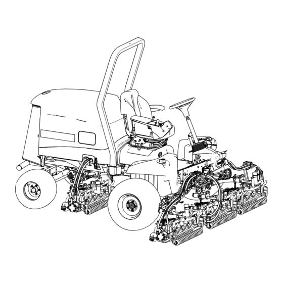
- Page 1 Form No. 3455-817 Rev A Reelmaster ® 5610-D Traction Unit Model No. 03956—Serial No. 400000000 and Up *3455-817* Register at www.Toro.com. Original Instructions (EN)
- Page 2 It is a violation of California Public Resource Code additional information, contact an Authorized Service Section 4442 or 4443 to use or operate the engine on Dealer or Toro Customer Service and have the model any forest-covered, brush-covered, or grass-covered and serial numbers of your product ready.
-
Page 3: Table Of Contents
Replacing a 12 V Fuse-Block Fuse ....74 Understanding the Warm-Up Mode....37 Replacing the TEC Fuse........74 Understanding Toro Smart Power™ ....37 Replacing the ECU Fuse ........74 Starting the Engine ........... 37 Drive System Maintenance ........75 Shutting Off the Engine........ -
Page 4: Safety
Safety Hydraulic System Safety........80 Hydraulic Fluid Specifications......80 Checking the Hydraulic-Fluid Level....80 General Safety Checking the Hydraulic Lines and Hoses............81 Hydraulic Fluid Capacity ........81 This product is capable of amputating hands and feet Changing the Hydraulic Fluid ......81 and of throwing objects. -
Page 5: Safety And Instructional Decals
Safety and Instructional Decals Safety decals and instructions are easily visible to the operator and are located near any area of potential danger. Replace any decal that is damaged or missing. decal106-6754 decalbatterysymbols 106-6754 Battery Symbols 1. Warning—do not touch the hot surface. Some or all of these symbols are on your battery. - Page 6 decal137-8127 137-8127 1. Attention—do not spray with high-pressure water. decal136-2159 136-2159 1. Move seat down 3. Rotate seat 2. Slide seat forward decal136-3702 136-3702 1. Warning—Read the 2. Warning—Do not modify Operator’s Manual; wear the roll bar. a seatbelt; do not remove the roll bar.
- Page 7 decal133-2930 133-2930 1. Warning—do not operate this machine unless you are trained. 4. Tipping hazard—drive slowly when turning; do not turn sharply while traveling fast; only drive on slopes with the cutting units lowered; always wear a seatbelt. 2. Warning—wear hearing protection. 5.
- Page 8 decal145-2483 145-2483 1. Parking brake 5. PTO—Disengage 2. Cruise control 6. PTO—Engage 3. Lower the cutting units. 7. Read the Operator’s Manual. 4. Raise the cutting units. decal145-2519 145-2519 1. TEC power relay 5. Air-ride seat 2. Electrical power relay 6.
- Page 9 decal145-2573 145-2573 1. Check every 8 hours. 8. Battery 15. Fuel/Water separator 2. Brake functions 9. Radiator screen 16. Fluids 3. Hydraulic fluid 10. Engine oil 17. Capacity 4. Tire pressure 11. Engine oil level 18. Fluid interval (hours) 5. Engine air filter 12.
-
Page 10: Setup
Setup Loose Parts Use the chart below to verify that all parts have been shipped. Procedure Description Qty. – No parts required Prepare the machine. – No parts required Adjust the control-arm position. Right front hose guide Install the cutting units. Left front hose guide Cutting-unit kickstand Install the cutting-unit kickstand. -
Page 11: Adjusting The Control-Arm Position
Adjusting the Control-Arm Installing the Cutting Units Position Parts needed for this procedure: Right front hose guide No Parts Required Left front hose guide Procedure Preparing the Machine You can adjust the control-arm position for your comfort. Remove the reel motors from the shipping brackets. - Page 12 g003320 Figure 5 1. Counterweight g375689 Figure 7 1. Hairpin Positioning the Turf Compensating Remove the 2 flange locknuts (3/8 inch) and 2 Spring and Installing the Hose carriage bolts (3/8 x 1-1/4 inches) that secure Guide the turf-compensator bracket to the cutting-unit frame (Figure Cutting Units 4...
- Page 13 g375691 Figure 9 g375687 Figure 11 1. Capscrew 3. Flange locknut (3/8 inch) 2. Right tab (Carrier frame) 1. Turf-compensator bracket 3. Stud (hose guide) 2. Flange locknut (3/8 inch) 4. Inboard Assemble the capscrew of the turf compensation spring to the right tab of the carrier frame (Figure Assemble the hose guide and turf-compensator 10) with the flange locknut (3/8 inch).
- Page 14 g375688 Figure 15 1. Stud (hose guide ) 3. Flange locknut (3/8 inch) 2. Turf-compensator bracket 4. Inboard Assemble the hose guide and turf-compensator bracket to the cutting-unit frame with the 2 flange g375689 Figure 13 locknuts (3/8 inch). 1. Hairpin Torque the locknuts to 37 to 45 N∙m (27 to 33 ft-lb).
- Page 15 g375691 Figure 19 1. Capscrew 3. Flange locknut (3/8 inch) 2. Right tab (Carrier frame) Assemble the capscrew of the turf compensation spring to the right tab of the carrier frame (Figure 20) with the flange locknut (3/8 inch). g375689 Figure 17 1.
- Page 16 Installing the Front Cutting Units to the Lift Arms Slide a cutting unit under the lift arm (Figure 23). g378789 Figure 21 1. Turf-compensator bracket 3. Flange locknut (3/8 inch) 2. Carriage bolt (3/8 x 1-1/4 4. Inboard inches) g375274 Figure 23 Assemble the turf-compensator bracket to the 1.
- Page 17 g375236 Figure 25 1. Lynch pin 3. Lift arm (rear cutting unit) 2. Pivot yoke 4. Washer Assemble the pivot yoke onto the carrier frame shaft (Figure 26). g375252 Figure 24 1. Cap 3. Pivot yoke 2. Snapper pin 4. Carrier frame shaft Assemble the pivot yoke onto the carrier frame shaft.
- Page 18 g375239 g003948 Figure 27 Figure 29 1. Lynch pin 3. Lift arm 1. Lift-arm chain 3. Snapper pin 2. Lift-arm shaft 4. Washer 2. Chain bracket Insert the pivot yoke into the lift arm, and secure shaft to the arm with the lynch pin and washer. Installing the Reel Motors Repeat steps through...
-
Page 19: Using The Cutting-Unit Kickstand
Using the Cutting-Unit Kickstand Parts needed for this procedure: Cutting-unit kickstand Procedure Whenever you need to tip the cutting unit to expose the bedknife/reel, prop up the rear of the cutting unit with the kickstand to make sure that the nuts on the g004144 back end of the bedbar-adjusting screws are not Figure 32... - Page 20 Close the hood, and use the enclosed hood-latch key to check that the hook of the lock engages the frame catch when locked. g004143 Figure 33 1. Rubber grommet Ensure that the seal is assembled to the hood lock (Figure 34).
-
Page 21: Applying The Ce Decals
Applying the CE Decals Parts needed for this procedure: CE decal g375339 Production year decal Figure 36 Warning decal 1. Year of production decal 2. Serial plate Applying the CE Decal Remove the backing from the year of production decal. Use rubbing alcohol and a clean rag to clean Apply the decal to the floor bracket. -
Page 22: Product Overview
Product Overview g383839 Figure 40 1. Traction pedal 2. Tilt steering pedal Automotive-Style Throttle g216864 Note: This machine does not have a lever or switch Figure 38 to control the engine speed. 1. Engine hood 5. Seat adjustments When the PTO is engaged to start spinning the 2. - Page 23 Key Switch units. When you lower the cutting units before the PTO switch is engaged, they do not start spinning. The key switch (Figure 39) has 3 positions: O To fully raise the cutting units, pull the lever backward. , and S REHEAT TART When the cutting units are raised and the PTO switch...
-
Page 24: Seat Controls
To ensure optimum performance and continued safety Use the backlap levers in conjunction with the lower certification of the machine, use only genuine Toro mow/raise control lever for backlapping the reels replacement parts and accessories. Replacement (Figure 45). -
Page 25: Before Operation
Operation • Do not add or drain fuel in an enclosed space. • Do not store the machine or fuel container where there is an open flame, spark, or pilot light, such Note: Determine the left and right sides of the as on a water heater or other appliance. -
Page 26: Checking The Interlock Switches
Fuel filter plugging may be expected for a time after converting to biodiesel blends. Preparing the Machine • Contact your authorized Toro distributor for more information on biodiesel. Drive the machine slowly to an open area. Lower the cutting units, shut off the engine, and Adding Fuel engage the parking brake. -
Page 27: Using The Infocenter Lcd Display
Press the PTO switch to the D position. operator’s seat, indicating that the parking brake ISENGAGE is on. Press the traction pedal. Rotate the key to the S position. TART Checking the Cutting Unit Lower Note: The starter should not crank the engine Disable Interlock with the traction pedal pressed. - Page 28 Note: The purpose of each button may change The PTO is engaged. depending on what is required at the time. Each button is labeled with an icon displaying its current function. Not allowed Start the engine. InfoCenter Icon Description Hours remaining until service Shut off the engine.
-
Page 29: Using The Menus
NOx control diagnosis malfunction; Parked Regen Use to initiate a parked drive the machine back to the shop regeneration and contact your authorized Toro Last Regen Lists the number hours since distributor (software version U and the last reset, parked, or later). -
Page 30: Protected Menus
Controls the maximum speed Mow Speed If you changed the PIN code and forgot the code, while in mow (low range) contact your authorized Toro distributor for assistance. Controls the maximum speed Trans. Speed From the M , use the center button to... - Page 31 Setting the Service Due Timer The service due timer resets the service due hours after a scheduled maintenance procedure is performed. In the Settings Menu, use the center button to scroll down to the P and press ROTECTED the right button. Enter PIN;...
-
Page 32: Checking The Hydrostatic Braking Distance
(3.7 m or 12 ft). traction-speed bar graph along with the cruise control and pedal stop settings. An X in a bar denotes that the Contact your Toro distributor if the stopping maximum speed is limited by the supervisor (Figure distance of the machine is not within 0.6 m (2... -
Page 33: Understanding Displayed Traction Speeds
– Park the machine on a level surface. • Contact your authorized Toro distributor if the – Disengage and lower the cutting units. machine's observed speeds deviate more than 2.4 km/h (1.5 mph) from the displayed speeds. -
Page 34: Understanding The Operating Characteristics Of The Machine
Understanding the • Check carefully for overhead obstructions and do not contact them. Operating Characteristics • Keep the ROPS in safe operating condition by thoroughly inspecting it periodically for damage of the Machine and keeping all the mounting fasteners tight. •... -
Page 35: Using The Traction Pedal
Using the Virtual Pedal remove your foot from the traction pedal and let it return to N EUTRAL Stop (VPS) Feature Note: When going downhill in the machine, you may need to use the reverse pedal to stop. The virtual pedal stop (VPS) feature allows you to temporarily set a maximum traction speed that is less •... -
Page 36: Operating The Cruise Control
Operating the Cruise Control Setting the Cruise Control The cruise-control switch locks in the cruise control to maintain the desired ground speed. Pressing the rear of the switch turns the cruise control off, the middle position of the switch enables the cruise-control function, and the front of the switch sets the desired ground speed. -
Page 37: Understanding The Warm-Up Mode
Park the machine approximately 6 m (20 ft) operate the machine until after the warm-up period. off the fairway, facing the intended mowing direction. Understanding Toro Smart Lower the cutting units completely with the Power™ lift/lower control lever. Engage the PTO. -
Page 38: Diesel Particulate Filter Regeneration
• Press the lift/lower control lever to automatically Passive regeneration occurs continuously while lower the cutting units from the turnaround the engine is running—run the engine at full position and continue mowing. engine speed when possible to promote DPF regeneration. After mowing the desired area, follow the perimeter of the area to complete the cleanup •... - Page 39 DPF Ash Accumulation • When enough ash accumulates, the engine computer sends information to the InfoCenter • The lighter ash is discharged through the exhaust in the form of an engine fault to indicate the system; the heavier ash collects in the soot filter. accumulation of ash in the DPF.
- Page 40 Types of Diesel Particulate Filter Regeneration Types of diesel particulate filter regeneration that are performed while the machine is operating: Type of Regeneration Conditions that cause DPF regeneration DPF description of operation Passive Occurs during normal operation of the machine at •...
- Page 41 Types of diesel particulate filter regeneration that require you to park the machine: (cont'd.) Type of Regeneration Conditions that cause DPF regeneration DPF description of operation Recovery Occurs because the operator ignored requests for • When the reset-standby/parked or recovery a parked regeneration and continued operating the machine, adding more soot to the DPF regeneration icon...
- Page 42 press the right button to select the Technician entry DPF Operation Table (cont'd.) (Figure 61). State Description Reset Regen The engine computer is running a reset regeneration. The engine computer is requesting that Parked Stby you run a parked regeneration. Parked Regen You initiated a parked regeneration request and the engine computer is...
- Page 43 Assist DPF Regeneration • The icon displays in the InfoCenter while the reset regeneration is processing. • The engine computer adjusts engine settings to • Whenever possible, do not shut off the engine or raise the exhaust temperature. reduce engine speed while the reset regeneration •...
- Page 44 g227304 g224394 Figure 66 Figure 68 Press the right button to change the inhibit Note: If the engine exhaust temperature is too low, regeneration setting from On to Off (Figure the InfoCenter displays A #186 (Figure 69) to DVISORY or from Off to On (Figure 67).
- Page 45 Parked or Recovery Regeneration regeneration required—power takeoff disabled #189 (Figure 73). DVISORY • When the engine computer requests either a parked regeneration or a recovery regeneration, the regeneration request icon (Figure 70) displays in the InfoCenter. g224398 Figure 73 Important: Perform a parked regeneration to restore the PTO function;...
- Page 46 Important: Perform a recovery regeneration Move the machine outside to an area away from to restore the PTO function; refer to Preparing combustible materials. to Perform a Parked or Recovery Regeneration Park the machine on a level surface. (page 46) Performing a Parked or Recovery Regeneration (page 46).
- Page 47 At the DPF checklist screen, verify that the parking brake is engaged and that the engine speed is set to low idle (Figure 81). g224402 g224407 g224629 Figure 79 At the V screen, verify that you g227679 ERIFY FUEL LEVEL Figure 81 have 1/4 tank of fuel if you are performing the parked regeneration or 1/2 tank of fuel if you are...
- Page 48 The InfoCenter displays the I NITIATING Check Message and Corrective Action Table message (Figure 83). EGEN (cont'd.) g224411 Corrective Action: Start and run the engine. g227681 Figure 83 Corrective Action: Run the engine to warm the coolant The InfoCenter displays the time to complete temperature to 60°C (140°F).
-
Page 49: Adjusting The Turf-Compensation Spring
Canceling a Parked or Recovery Regeneration displays A #183 (Figure 86). Press the DVISORY left button to exit to the home screen. Use the Parked Regen Cancel or Recovery Regen Cancel setting to cancel a running parked or recovery regeneration process. Access the DPF Regeneration menu (Figure 88). -
Page 50: Adjusting The Lift-Arm Counterbalance
Important: Note: Make spring adjustments with the To remove all counterbalance force, position cutting unit mounted to the traction unit, pointing the long leg of the torsion spring above the shouldered straight ahead and lowered to the ground. stud. Make sure that the hairpin cotter is installed in Park the machine on a level surface, lower the the rear hole in the spring rod (Figure... - Page 51 g375696 Figure 93 1. Switch 2. Lift-arm sensing device Adjust the lift-arm switch as follows: • To increase the lift-arm turnaround height, move the switch down. • To decrease the lift-arm turnaround height, move the switch up. Important: Maintain an air gap of 1.0 to 2.5 mm (0.040 to 0.100 inches) between the switch and the lift-arm trigger.
-
Page 52: Setting The Reel Speed
Setting the Reel Speed Important: It is important that proper reel speeds are used for your mowing application. Reel speeds that are too slow may result in a wave pattern in the turf, also known as clip marks, marcelling, or bobbing. If this is observed, try increasing the reel speeds or reducing the mowing speed. Reel speeds that are too fast may result in turf damage and/or premature wear of the reels, bedknives, and other mechanical components. -
Page 53: Operating Tips
Operating Tips Understanding the Warning System If a warning light comes on during operation, stop the machine immediately and correct the problem before continuing operation. Serious damage could occur if you operate the machine with a malfunction. Transporting the Machine Disengage the PTO and raise the cutting units to g021272 the T... -
Page 54: After Operation
• – For 5-inch verticutters, set the verticutter Disengage and lower the cutting units. blade depth to 1/8 inch or less. For 7-inch • Engage the parking brake. verticutters, set the blade depth to 1/4 inch or • Shut off the engine and remove the key. less. -
Page 55: Hauling The Machine
g004555 Figure 97 1. Rear tie-down Hauling the Machine • Use full-width ramps for loading the machine onto a trailer or truck. g420085 Figure 98 • Tie the machine down securely. Loosen the valves with 3 turns to allow the oil to Pushing or Towing the bypass internally. - Page 56 g420086 Figure 99 1. Pump mechanism on the 2. Black knob brake manifold Insert the long end of a ratchet or similar object, hold the black knob in on the manifold, and pump the manifold 3 times. As soon as there is substantial resistance when pumping the brake is released.
-
Page 57: Maintenance
• To ensure safe, optimal performance of the slip-resistant footwear. Keep hands, feet, clothing, machine, use only genuine Toro replacement jewelry, and long hair away from moving parts. parts. Replacement parts made by other •... - Page 58 Maintenance Service Maintenance Procedure Interval • Inspect the cooling-system hoses. Every 100 hours • Check the condition and tension of the alternator belt. • Change the engine oil and filter. Every 250 hours • Torque the wheel lug nuts to 94 to 122 N∙m (70 to 90 ft-lb). •...
-
Page 59: Daily Maintenance Checklist
Daily Maintenance Checklist Duplicate this page for routine use. For the week of: Maintenance Check Item Mon. Tues. Wed. Thurs. Fri. Sat. Sun. Check the safety interlock operation. Check the brake operation. Check the engine oil and fuel level. Drain the water/fuel separator. Check the air filter restriction indicator. -
Page 60: Pre-Maintenance Procedures
Pre-Maintenance Closing the Hood Procedures Carefully rotate the hood closed (Figure 101). Preparing for Maintenance Park the machine on a level surface, disengage the PTO, lower the cutting units, and engage the parking brake. Shut off the engine, remove the key, and wait for all moving parts to stop. -
Page 61: Tilting The Seat
Jacking Point Locations Note: Support the machine with jack stands whenever you work under the machine. Use the following as machine-lift points: g378174 Figure 103 1. Ball pin 2. Screen latch Insert the ball pin through the screen latch. Tilting the Seat Unlatch the seat base (A of Figure 104). -
Page 62: Lubrication
Lubrication • Lift-arm pivots (1 each) (Figure 107) • Cutting-unit carrier-frame and pivot (2 each) (Figure 108) Greasing the Bearings and Bushings Service Interval: Every 50 hours (and immediately after every washing). Grease Specification: No. 2 lithium grease Prepare the machine for maintenance; refer to Preparing for Maintenance (page 60). -
Page 63: Engine Maintenance
Engine Maintenance • Axle-steering pivot (1) (Figure 111) Engine Safety • Shut off the engine before checking the oil or adding oil to the crankcase. • Do not change the governor speed or overspeed the engine. Checking the Air Filter g004169 Figure 111 Service Interval: Before each use or daily... -
Page 64: Servicing The Air Cleaner
g034923 g373568 Figure 114 Close and latch the hood; refer to Closing the Hood (page 60). Servicing the Air Cleaner Service Interval: Every 400 hours (more frequently in extremely dirty or dusty conditions). Service the air cleaner earlier if the air-cleaner indicator shows red. -
Page 65: Resetting The Air Filter Service Indicator
Preferred oil: SAE 15W-40 (above -18°C (0°F)) • Alternate oil: SAE 10W-30 or 5W-30 (all temperatures) Toro Premium Engine Oil is available from your authorized Toro distributor in either 15W-40 or 10W-30 viscosity grades. Checking the Level of the Engine... - Page 66 Crankcase Oil Capacity Open the hood; refer to Opening the Hood (page 60). 5.2 L (5.5 US qt) with the filter Add oil to the crankcase; refer to Oil Specification (page 65), Crankcase Oil Capacity (page 66), Changing the Engine Oil and Filter Checking the Level of the Engine Oil (page 65).
-
Page 67: Fuel System Maintenance
Fuel System provider to correct the problem and perform all fuel system maintenance. Maintenance • Do not store diesel fuel in tanks or canisters made with zinc-plated components. Fuel Maintenance Servicing the Fuel-Water This Operator’s Manual contains more detailed Separator fuel and fuel system maintenance information than the Yanmar ®... -
Page 68: Servicing The Fuel Filter
g378468 Figure 121 1. Fuel-filter head 2. Fuel filter Remove the filter and clean the filter-head mounting surface (Figure 121). Note: Use a clean cloth to clean the filter head. Lubricate the filter gasket with clean lubricating engine oil; refer to the engine owner's manual for additional information. -
Page 69: Inspecting The Fuel Lines And Connections
Inspecting the Fuel Lines Contact your authorized Toro distributor to reset the engine ECU after you install a clean DPF. and Connections Cleaning the Fuel-Pickup Service Interval: Every 400 hours/Yearly (whichever comes first) Tube Screen Inspect the fuel lines for deterioration, damage, or loose connections. - Page 70 g373884 Figure 124 1. 2-pin connector (machine 2. 2-socket connector (fuel wire harness) sender) g373883 Figure 126 Move the clamps that secure the hoses to the fittings of the fuel sender inboard, and remove 1. Cap (fuel sender) the hoses from the fittings (Figure 125).
- Page 71 Cleaning the Installing the Fuel-Pickup Tube Clean the screen at the end of the fuel pick-up tube (Figure 127). g373882 Figure 129 1. Hoses 3. Fitting (fuel sender) 2. Clamp Plug the connector of the fuel-sender harness into the connector of the machine wire harness (Figure 130).
-
Page 72: Priming The Fuel System
Electrical System Maintenance Electrical System Safety • Disconnect the battery before repairing the machine. Disconnect the negative terminal first and the positive last. Connect the positive terminal first and the negative last. • Charge the battery in an open, well-ventilated area, away from sparks and flames. -
Page 73: Connecting The 12 V Battery
Apply a coat of Grafo 112X (skin-over) grease, Toro Part No. 505-47 to the battery posts and battery-cable clamps. Slide the rubber boot over the positive battery-cable clamp. Assemble the cover over the battery, inserting the tabs of the cover into the slots in the battery tray. -
Page 74: Replacing A 12 V Fuse-Block Fuse
Replacing a 12 V Fuse-Block Fuse The fuse block is under the seat. Prepare the machine for maintenance; refer to Preparing for Maintenance (page 60). Unlatch the seat base, tilt the seat base open, and support it with the prop rods (Figure 134). -
Page 75: Drive System Maintenance
Drive System Unlatch and open the hood; refer to Opening the Hood (page 60). Maintenance At the rear, right side of the engine, remove the cover of the in-line fuse holder. Checking the Tire Air Pressure Service Interval: Before each use or daily Important: Maintain the recommended pressure in all tires to ensure a good quality of cut and... -
Page 76: Adjusting The Rear Wheel Toe-In
Note: The rear wheel toe-in adjustment is At axle height, measure the center-to-center correct if the difference between the front wheel distance at the front and rear of the steering measurement and the rear wheel measurement tires. is 6 mm (1/4 inch) or less. (Figure 139). -
Page 77: Cooling System Maintenance
Cooling System • Preferred option: If distilled water is not available, use a pre-mix coolant instead of a concentrate. Maintenance • Minimum requirement: If distilled water and pre-mix coolant are not available, mix concentrated coolant with clean drinkable water. Cooling System Safety •... -
Page 78: Removing Debris From The Cooling System
Removing Debris from the Cooling System Service Interval: Before each use or daily (More frequently in dirty operating conditions). Every 100 hours—Inspect the cooling-system hoses. Every 2 years—Flush and replace the cooling-system fluid. Park the machine on a level surface, lower the cutting units, shut off the engine, engage the parking brake, and remove the key. -
Page 79: Belt Maintenance
Belt Maintenance Tensioning the Alternator Belt Service Interval: After the first 8 hours—Check the condition and tension of the alternator belt. Every 100 hours—Check the condition and tension of the alternator belt. Prepare the machine for maintenance; refer to Preparing for Maintenance (page 60). -
Page 80: Hydraulic System Maintenance
Toro. system. This fluid is compatible with the elastomers used in Toro hydraulic systems and is suitable for a Hydraulic Fluid wide-range of temperature conditions. This fluid is compatible with conventional mineral oils, but for... -
Page 81: Checking The Hydraulic Lines And Hoses
If the fluid becomes contaminated, contact your Toro Distributor because the system must be flushed. Contaminated fluid looks milky or black when compared to clean fluid. -
Page 82: Replacing The Hydraulic Filters
Important: Use only the hydraulic fluids specified. Other fluids could cause system damage. Install the tank cap. Start the engine, and use all the hydraulic controls to distribute hydraulic fluid throughout the system. Check for hydraulic-fluid leaks; refer to Checking for Leaks (page 83). -
Page 83: Cutting-Unit System Maintenance
Note: Additional instructions and procedures on Shut off the engine, remove the key, and check backlapping are available in the Toro Reel Mower for leaks at the return and charge filters. Basics (with sharpening guidelines), Form 09168SL. Note: Repair all hydraulic leaks. - Page 84 Make initial reel-to-bedknife adjustments With the Mow/Transport lever in the M appropriate for backlapping on all cutting units position, move the Enable/Disable switch to which are to be backlapped; refer to the cutting the E position. Move the Lower Mow/Lift NABLE unit Operator's Manual.
-
Page 85: Chassis Maintenance
Chassis Maintenance Inspecting the Seat Belt Service Interval: Before each use or daily Inspect the seat belt for wear, cuts, and other damage. Replace the seat belt(s) if any component does not operate properly. g377117 Clean the seat belt as necessary. Figure 151 Lower and latch the operator’s seat;... -
Page 86: Extended Maintenance
Extended Maintenance Cleaning Chassis and Engine Washing the Machine Service Interval: Every 2 years—Replace the Wash the machine as needed using water alone hydraulic hoses. or with a mild detergent. You may use a rag when washing the machine. Every 2 years—Replace the coolant hoses. Important: Do not use brackish or reclaimed Every 2 years—Flush and replace the coolant. -
Page 87: Storage
Clean the battery, terminals, and posts with a wire brush and baking-soda solution. Coat the cable terminals and battery posts with Grafo 112X skin-over grease (Toro Part No. 505-47) or petroleum jelly to prevent corrosion. Slowly charge the battery every 60 days for 24 hours to prevent lead sulfation of the battery. - Page 88 Notes:...
- Page 89 The Toro Company (“Toro”) respects your privacy. When you purchase our products, we may collect certain personal information about you, either directly from you or through your local Toro company or dealer. Toro uses this information to fulfil contractual obligations - such as to register your warranty, process your warranty claim or to contact you in the event of a product recall - and for legitimate business purposes - such as to gauge customer satisfaction, improve our products or provide you with product information which may be of interest.
- Page 90 While the exposure from Toro products may be negligible or well within the “no significant risk” range, out of an abundance of caution, Toro has elected to provide the Prop 65 warnings. Moreover, if Toro does not provide these...
- Page 91 Countries Other than the United States or Canada Customers who have purchased Toro products exported from the United States or Canada should contact their Toro Distributor (Dealer) to obtain guarantee policies for your country, province, or state. If for any reason you are dissatisfied with your Distributor's service or have difficulty obtaining guarantee information, contact your Authorized Toro Service Center.