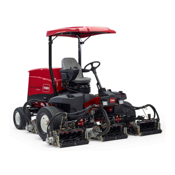
Toro Reelmaster 5610-D Operator's Manual
Traction unit
Hide thumbs
Also See for Reelmaster 5610-D:
- Operator's manual (124 pages) ,
- Owner's manual (84 pages) ,
- Service manual (662 pages)

Related Manuals for Toro Reelmaster 5610-D


Summary of Contents for Toro Reelmaster 5610-D
- Page 1 Form No. 3428-163 Rev A Reelmaster ® 5610-D Traction Unit Model No. 03679—Serial No. 403410001 and Up *3428-163* A Register at www.Toro.com. Original Instructions (EN)
- Page 2 It is a violation of California Public Resource Code additional information, contact an Authorized Service Section 4442 or 4443 to use or operate the engine on Dealer or Toro Customer Service and have the model and serial numbers of your product ready. Figure 1...
-
Page 3: Table Of Contents
Contents Checking the Fuel Lines and Connections..........54 Cleaning the Fuel Pick-Up Tube Screen.... 54 Safety ............... 4 Electrical System Maintenance ......55 General Safety........... 4 Electrical System Safety ........55 Engine Emission Certification ......4 Servicing the Battery......... 55 Safety and Instructional Decals ...... -
Page 4: Safety
Safety This machine has been designed in accordance with EN ISO 5395 (when you complete the setup procedures) and ANSI B71.4-2017. General Safety This product is capable of amputating hands and feet and of throwing objects. • Read and understand the contents of this Operator’s Manual before starting the engine. -
Page 5: Safety And Instructional Decals
Safety and Instructional Decals Safety decals and instructions are easily visible to the operator and are located near any area of potential danger. Replace any decal that is damaged or missing. decal93-6689 93-6689 1. Warning—do not carry passengers. decal106-6755 106-6755 1. - Page 6 decal110-9642 110-9642 1. Stored energy hazard—read the Operator's Manual. 2. Move the cotter pin to the hole closest to the rod bracket and then remove the lift arm and pivot yoke. decal125-8754 125–8754 1. Head lights 6. Slow 2. Engage 7.
- Page 7 decal133-2930 133-2930 1. Warning—do not operate this machine unless you are trained. 4. Tipping hazard—drive slowly when turning; do not turn sharply while traveling fast; only drive on slopes with the cutting units lowered; always wear a seatbelt. 2. Warning—wear hearing protection. 5.
- Page 8 decalbatterysymbols Battery Symbols Some or all of these symbols are on your battery. 1. Explosion hazard 6. Keep bystanders away from the battery. 2. No fire, open flame, or 7. Wear eye protection; smoking explosive gases can cause blindness and other injuries.
-
Page 9: Setup
Setup Loose Parts Use the chart below to verify that all parts have been shipped. Procedure Description Qty. – No parts required Adjust the tire pressure. – No parts required Adjust the control-arm position. Right front hose guide Install the cutting units. Left front hose guide –... -
Page 10: Adjusting The Control-Arm Position
Adjusting the Control-Arm Installing the Cutting Units Position Parts needed for this procedure: Right front hose guide No Parts Required Left front hose guide Procedure Procedure You can adjust the control-arm position for your comfort. Remove the reel motors from the shipping brackets. - Page 11 Remove the 2 carriage bolts and nuts securing the rod bracket to the cutting-unit tabs (Figure g030896 Figure 7 1. Cutting unit 1 5. Cutting unit 5 g003949 Figure 5 2. Cutting unit 2 6. Reel motor 3. Cutting unit 3 7.
- Page 12 g019284 Figure 9 1. Hose guides must lean toward the center cutting unit. Note: When installing or removing the cutting units, make sure the hairpin cotter is installed in the spring rod hole next to the rod bracket. Otherwise, the hairpin cotter must be installed in the hole in the end of the rod.
- Page 13 Note: Rotate the motor counterclockwise until the flanges encircle the bolts then tighten the bolts. Important: Make sure that the reel-motor hoses are not twisted, kinked or in the risk of being pinched. g003979 Figure 12 1. Lynch pin and washer Insert the lift-arm yoke onto the carrier-frame shaft (Figure...
-
Page 14: Adjusting The Turf-Compensation Spring
Adjusting the Installing the CE Hood Turf-Compensation Spring Latch Parts needed for this procedure: No Parts Required Hood latch assembly Procedure Washer The turf-compensation spring transfers weight from Procedure the front to the rear roller (Figure 15). This helps to reduce a wave pattern in the turf, also known as Unlatch and raise the hood. -
Page 15: Using The Cutting-Unit Kickstand
Outside the hood, insert the hook end of the latch through the hole in the hood. Note: Make sure that the rubber sealing washer remains to the outer side of the hood. Inside the hood, insert the metal washer onto the latch and secure with the nut. -
Page 16: Product Overview
Traction Pedal Product Overview The traction pedal controls the forward and reverse operation (Figure 22). Press the top of the pedal to move forward and the bottom to move rearward. The ground speed depends on how far you press the pedal. - Page 17 Tilt-Steering Pedal Lower Mow/Raise Control Lever To tilt the steering wheel toward you, press the foot This lever raises and lowers the cutting units and also pedal down, pull the steering tower toward you to starts and stops the cutting units when the cutting the most comfortable position, and release the pedal units are enabled in the M mode...
- Page 18 Hydraulic-Filter-Restriction Using the InfoCenter LCD Display Indicator The InfoCenter LCD display shows information about your machine, such as the operating status, various With the engine running at normal operating diagnostics, and other information about the machine temperature, ensure that the indicator is in the green (Figure 27).
- Page 19 InfoCenter Icon Description Start the engine. Hours remaining until service Shut off the engine. Reset the service hours Engine SERVICE DUE Indicates when scheduled service should be performed Key switch Engine rpm/status—indicates the engine speed (rpm) The cutting units are lowering. Hour meter The cutting units are raising.
- Page 20 A parked or recovery regeneration is processing. High exhaust temperature NOx control diagnosis malfunction; drive the machine back to the shop and contact your authorized Toro distributor (software version U and later). The power take-off is disabled. Sit down or engage the parking brake.
- Page 21 Indicates the inputs, qualifiers machine faults. Refer to the and outputs for driving in Service Manual or contact your transport mode. authorized Toro distributor for more information on the Faults Indicates the inputs, qualifiers menu and the information and outputs for enabling the contained there.
- Page 22 If you changed the PIN code and forgot the code, Displays the calculated reel R Reel RPM speed position for the rear contact your authorized Toro distributor for assistance. reels. The reels can also be manually adjusted. From the M...
- Page 23 Setting the Mow Speed Press the middle button to enter the PIN code (Figure 29D). In the Settings Menu, scroll down to Mow Speed. Wait until the red indicator light of the InfoCenter Press the right button to select mow speed. illuminates.
-
Page 24: Specifications
Contact your Authorized Service Dealer or authorized Toro distributor or go to www.Toro.com for a list of all Before Operation approved attachments and accessories. To ensure optimum performance and continued safety... -
Page 25: Performing Daily Maintenance
Fuel filter plugging may be expected for a time diesel fuel. after converting to biodiesel blends. • Never keep fuel in containers with zinc plating on • Contact your authorized Toro distributor for more the inside. information on biodiesel. • Do not use fuel additives. Adding Fuel... -
Page 26: During Operation
• Using a clean rag, clean area around fuel-tank Avoid mowing on wet grass. Reduced traction cap. could cause the machine to slide. • Remove the cap from the fuel tank (Figure 30). Keep your hands and feet away from the cutting units. -
Page 27: Starting The Engine
injury or death. You are responsible for safe slope to the M position, and ensure that the IDDLE operation. Operating the machine on any slope Enable/Disable switch is in the D position. ISABLE requires extra caution. Remove your foot from the traction pedal and •... -
Page 28: Diesel Particulate Filter Regeneration
Diesel Particulate Filter Operate and maintain your machine with the function of the DPF in mind. Engine load at high idle (full Regeneration throttle) engine speed generally produces adequate exhaust temperature for DPF regeneration. The diesel particulate filter (DPF) is part of the exhaust Important: Minimize the amount of time that you system. - Page 29 DPF Ash Accumulation • When enough ash accumulates, the engine computer sends information to the InfoCenter • The lighter ash is discharged through the exhaust in the form of an engine fault to indicate the system; the heavier ash collects in the soot filter. accumulation of ash in the DPF.
- Page 30 Types of Diesel Particulate Filter Regeneration Types of diesel particulate filter regeneration that are performed while the machine is operating: Type of Regeneration Conditions that cause DPF regeneration DPF description of operation Passive Occurs during normal operation of the machine at •...
- Page 31 Types of diesel particulate filter regeneration that require you to park the machine: (cont'd.) Type of Regeneration Conditions that cause DPF regeneration DPF description of operation Recovery Occurs because the operator ignored requests for • When the reset-standby/parked or recovery a parked regeneration and continued operating the machine, adding more soot to the DPF regeneration icon...
- Page 32 press the right button to select the Technician entry DPF Operation Table (cont'd.) (Figure 38). State Description Reset Regen The engine computer is running a reset regeneration. The engine computer is requesting that Parked Stby you run a parked regeneration. Parked Regen You initiated a parked regeneration request and the engine computer is...
- Page 33 Assist DPF Regeneration • The icon displays in the InfoCenter while the reset regeneration is processing. • The engine computer adjusts engine settings to • Whenever possible, do not shut off the engine or raise the exhaust temperature. reduce engine speed while the reset regeneration •...
- Page 34 g227304 g224394 Figure 43 Figure 45 Press the right button to change the inhibit Note: If the engine exhaust temperature is too low, regeneration setting from On to Off (Figure the InfoCenter displays A #186 (Figure 46) to DVISORY or from Off to On (Figure 44).
- Page 35 Parked or Recovery Regeneration regeneration required—power takeoff disabled #189 (Figure 50). DVISORY • When the engine computer requests either a parked regeneration or a recovery regeneration, the regeneration request icon (Figure 47) displays in the InfoCenter. g224398 Figure 50 Important: Perform a parked regeneration to restore the PTO function;...
- Page 36 Important: Perform a recovery regeneration Move the machine outside to an area away from to restore the PTO function; refer to Preparing combustible materials. to Perform a Parked or Recovery Regeneration Park the machine on a level surface. (page 36) Performing a Parked or Recovery Regeneration (page 36).
- Page 37 At the DPF checklist screen, verify that the parking brake is engaged and that the engine speed is set to low idle (Figure 58). g224402 g224407 g224629 Figure 56 At the V screen, verify that you g227679 ERIFY FUEL LEVEL Figure 58 have 1/4 tank of fuel if you are performing the parked regeneration or 1/2 tank of fuel if you are...
- Page 38 The InfoCenter displays the I NITIATING Check Message and Corrective Action Table message (Figure 60). EGEN (cont'd.) g224411 Corrective Action: Start and run the engine. g227681 Figure 60 Corrective Action: Run the engine to warm the coolant The InfoCenter displays the time to complete temperature to 60°C (140°F).
-
Page 39: Adjusting The Lift-Arm Counterbalance
Canceling a Parked or Recovery Regeneration displays A #183 (Figure 63). Press the DVISORY left button to exit to the home screen. Use the Parked Regen Cancel or Recovery Regen Cancel setting to cancel a running parked or recovery regeneration process. Access the DPF Regeneration menu (Figure 65). -
Page 40: Adjusting The Lift-Arm Turnaround Position
Adjusting the Lift-Arm You can adjust each counterbalance spring to 1 of 4 settings. Each increment increases or decreases Turnaround Position counterbalance on the cutting unit by 2.3 kg (5 lb). You can position the springs on the back side of the Park the machine on a level surface, lower the first spring actuator to remove all counter balance cutting units, engage the parking brake, shut off... - Page 41 g031995 Figure 69 5 inch (127 mm) Reel Speed Chart g031996 Figure 70 7 inch (177.8 mm) Reel Speed Chart...
-
Page 42: Understanding The Diagnostic Light
Understanding the Verifying the Interlock-Switch Function Diagnostic Light Service Interval: Before each use or daily The machine is equipped with a diagnostic light, which Park the machine on a level surface, lower the indicates if the machine detects a malfunction. The cutting units, engage the parking brake, shut off diagnostic light is located on the InfoCenter, above the engine, and remove the key. -
Page 43: Operating Tips
Operating Tips • Clean grass and debris from the cutting units, drives, mufflers, cooling screens, and engine compartment to help prevent fires. Clean up oil or Becoming Familiarized with the fuel spills. Machine • Shut off the fuel while storing or hauling the machine. -
Page 44: Jacking Points
Pushing or Towing the Machine In an emergency, you can move the machine by actuating the bypass valve in the variable displacement hydraulic pump and pushing or towing the machine. Important: Do not push or tow the machine faster than 3 to 4.8 km/h (2 to 3 mph) because internal transmission damage may occur. - Page 45 Rear reel circuit SVRV Lift/lower cutting units Lift/lower front cutting units Lift/lower rear cutting units Raise any cutting units...
-
Page 46: Maintenance
• To ensure safe, optimal performance of the – Shut off the engine and remove the key. machine, use only genuine Toro replacement – Wait for all movement to stop. parts. Replacement parts made by other manufacturers could be dangerous, and such use •... - Page 47 Maintenance Service Maintenance Procedure Interval • Check the rear wheel toe-in. • If you are not using the recommended hydraulic fluid or have ever filled the reservoir with an alternative fluid, change the hydraulic fluid. Every 800 hours • If you are not using the recommended hydraulic fluid or have ever filled the reservoir with an alternative fluid, replace the hydraulic filters.
-
Page 48: Daily Maintenance Checklist
Refer to your engine owner’s manual and cutting unit Operator's Manual for additional maintenance procedures. Note: Download a free copy of the electrical or hydraulic schematic by visiting www.Toro.com and searching for your machine from the Manuals link on the home page. -
Page 49: Lubrication
Lubrication Greasing the Bearings and Bushings Service Interval: Every 50 hours (and immediately after every washing). Lubricate all grease fittings for the bearings and bushings with No. 2 lithium grease. The grease fitting locations and quantities are as follows: g003960 Figure 78 •... -
Page 50: Engine Maintenance
Engine Maintenance Engine Safety • Shut off the engine before checking the oil or adding oil to the crankcase. • Do not change the governor speed or overspeed the engine. g004169 Figure 81 Servicing the Air Cleaner Service Interval: Every 400 hours (more frequently in •... -
Page 51: Servicing The Engine Oil
Preferred oil: SAE 15W-40 (above -18°C (0°F)) • Alternate oil: SAE 10W-30 or 5W-30 (all temperatures) Toro Premium Engine Oil is available from your authorized Toro distributor in either 15W-40 or 10W-30 viscosity grades. Checking the Level of the Engine... - Page 52 Crankcase Oil Capacity 5.2 L (5.5 US qt) with the filter Changing the Engine Oil and Filter Service Interval: Every 250 hours g034922 g034924 g031256 Figure 85 Important: Be sure to keep the level of the engine oil between the upper and lower limits on the oil gauge.
-
Page 53: Servicing The Diesel-Oxidation Catalyst (Doc) And The Soot Filter
DPF. canister and open the vent on the top of the canister mount. Refer to your authorized Toro distributor for diesel-oxidation catalyst and the soot filter replacement parts or service. Contact your authorized Toro distributor to reset the engine ECU after you install a clean DPF. -
Page 54: Servicing The Engine Fuel Filter
Checking the Fuel Lines Remove the filter canister and clean the mounting surface. and Connections Lubricate the gasket on the filter canister with clean oil. Service Interval: Every 400 hours (or yearly, whichever comes first). Install the filter canister by hand until the gasket contacts mounting surface, then rotate it an Check the fuel lines and connections for deterioration, additional 1/2 turn. -
Page 55: Electrical System Maintenance
Electrical System WARNING Charging the battery produces gasses that Maintenance can explode. Never smoke near the battery and keep sparks WARNING and flames away from it. CALIFORNIA Keep the terminals and the entire battery case clean Proposition 65 Warning because a dirty battery discharges slowly. To clean Battery posts, terminals, and related the battery, wash the entire case with a solution of accessories contain lead and lead... -
Page 56: Drive System Maintenance
Drive System Maintenance Checking the Tire Pressure Service Interval: Before each use or daily Check the tire pressure. The correct air pressure in the front and rear tires is 83 to 103 kPa (12 to 15 psi). DANGER Low tire pressure decreases machine side hill stability. -
Page 57: Adjusting The Rear Wheel Toe-In
Adjusting the Rear Wheel Cooling System Toe-in Maintenance Service Interval: Every 800 hours—Check the rear wheel toe-in. Cooling System Safety Rotate the steering wheel to position the rear • Swallowing engine coolant can cause poisoning; wheels straight ahead. keep out of reach from children and pets. Loosen the jam nut on each end of the tie rod •... -
Page 58: Removing Debris From The Cooling System
g021866 Figure 94 1. Expansion tank If the coolant level is low, remove the g004138 Figure 95 expansion-tank cap and replenish the system. Do not overfill. 1. Rear-screen latch 2. Rear screen Install the expansion-tank cap. Thoroughly clean both sides of the radiator/oil cooler with compressed air (Figure 96). -
Page 59: Brake Maintenance
Brake Maintenance Note: Ensure that the cable conduit does not rotate while you are tightening the nuts. Adjusting the Parking Adjusting the Brakes Parking-Brake Latch Adjust the brakes when there is more than 2.5 cm (1 If the parking brake fails to engage and latch, adjust inch) of free travel of the brake pedal, or when more the brake pawl. -
Page 60: Belt Maintenance
Belt Maintenance Hydraulic System Maintenance Servicing the Alternator Belt Hydraulic System Safety Service Interval: After the first 10 hours • Seek immediate medical attention if fluid is injected into skin. Injected fluid must be surgically removed Every 100 hours within a few hours by a doctor. Note: For proper belt tension, allow 10 mm (3/8 inch) •... -
Page 61: Hydraulic Fluid Specifications
Do not overfill the hydraulic This fluid is compatible with the elastomers used tank. in Toro hydraulic systems and is suitable for a wide-range of temperature conditions. This fluid is If the level is low, add appropriate fluid to raise... -
Page 62: Replacing The Hydraulic Filters
Replacing the Hydraulic Park the machine on a level surface, lower the cutting units, engage the parking brake, shut off Filters the engine, and remove the key. Raise the hood. Service Interval: Every 1,000 hours—If you are using the recommended Place a large drain pan under the fitting secured hydraulic fluid, replace the to the bottom of the hydraulic-fluid reservoir... -
Page 63: Using The Hydraulic System Test Ports
Test Ports Use the test port on the lift manifold block to assist in Use the hydraulic-system test ports to test the troubleshooting the lift circuit (Figure 108). pressure in the hydraulic circuits. Contact your authorized Toro distributor for assistance. -
Page 64: Cutting-Unit System Maintenance
Cutting-Unit System Maintenance Blade Safety • A worn or damaged blade or bedknife can break, and a piece could be thrown toward you or bystanders, resulting in serious personal injury or death. • Inspect the cutting units periodically for excessive wear or damage. - Page 65 Make initial reel-to-bedknife adjustments appropriate for backlapping on all cutting units that are to be backlapped; refer to the Operator's Manual for the cutting units. Start the engine and run at low idle speed. DANGER Changing the engine speed while backlapping may cause the reels to stall.
-
Page 66: Cleaning
Clean the battery, terminals, and posts with a wire brush and baking-soda solution. Coat the cable terminals and battery posts with Grafo 112X skin-over grease (Toro Part No. 505-47) or petroleum jelly to prevent corrosion. Slowly charge the battery every 60 days for 24 hours to prevent lead sulfation of the battery. - Page 67 Flush the fuel tank with fresh, clean fuel. Secure all of the fuel-system fittings. Thoroughly clean and service the air-cleaner assembly. Seal the air-cleaner inlet and the exhaust outlet with weatherproof tape. Check the antifreeze protection and add a 50/50 solution of water and ethylene glycol antifreeze as needed for the expected minimum temperature in your area.
- Page 68 Notes:...
- Page 69 Notes:...
- Page 70 The Toro Company (“Toro”) respects your privacy. When you purchase our products, we may collect certain personal information about you, either directly from you or through your local Toro company or dealer. Toro uses this information to fulfil contractual obligations - such as to register your warranty, process your warranty claim or to contact you in the event of a product recall - and for legitimate business purposes - such as to gauge customer satisfaction, improve our products or provide you with product information which may be of interest.
- Page 71 While the exposure from Toro products may be negligible or well within the “no significant risk” range, out of an abundance of caution, Toro has elected to provide the Prop 65 warnings. Moreover, if Toro does not provide these warnings, it could be sued by the State of California or by private parties seeking to enforce Prop 65 and subject to substantial penalties.
- Page 72 Countries Other than the United States or Canada Customers who have purchased Toro products exported from the United States or Canada should contact their Toro Distributor (Dealer) to obtain guarantee policies for your country, province, or state. If for any reason you are dissatisfied with your Distributor's service or have difficulty obtaining guarantee information, contact your Authorized Toro Service Center.